Introduction
We all start with an idea and a plan. I started with an inkling of what flyback transformers were about, having seen common chokes being used for isolated signal coupling, and I had an itch I wanted to scratch.
I wanted to see if I could use flyback transformers as a type of energy harvesting power source to safely power a secondary system, when it’s needed for diagnostics and communication (using something like powerline narrowband communication) after a power failure. The intended target for this type of secondary monitoring device would be high voltage AC and DC powered systems where you would need isolation. In my ignorance, I thought the flyback transformer would be suitable for this purpose. So I’m using the design challenge to prove it, either way.
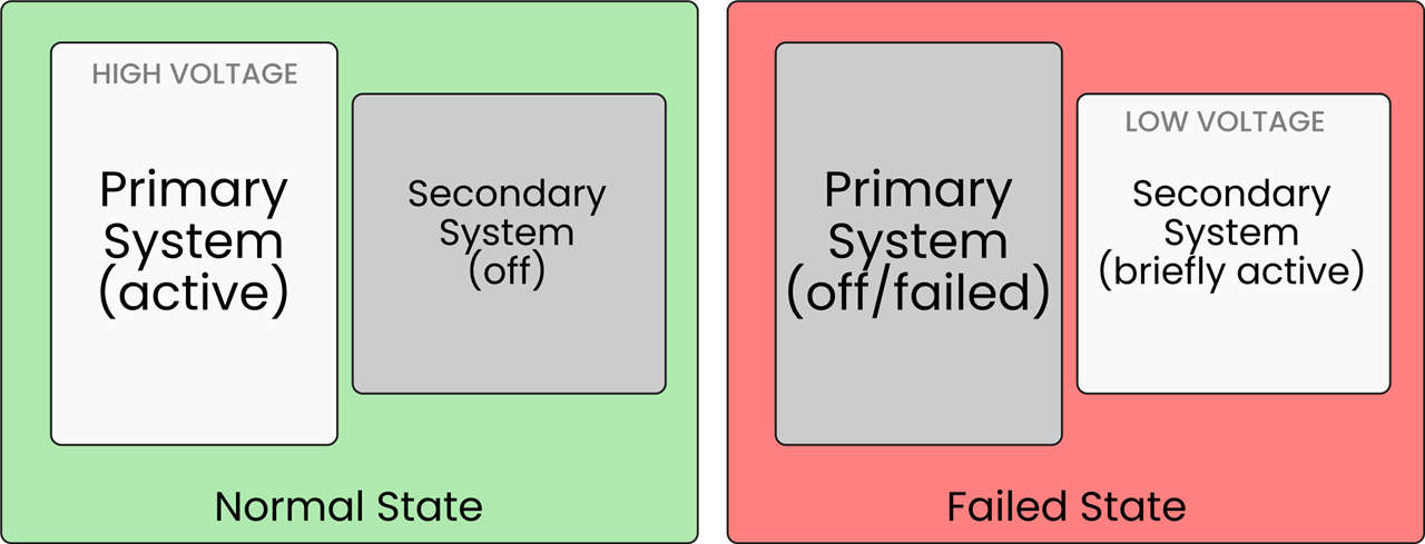
Now having started with a plan, I took my first steps to get things started (see next sections) and that’s quickly when I realised that assumption had gotten in the way and that plan of mine would need refinement by way of some fundamental design changes.
Little did I realise that my initial interpretation of flyback transformer documentation was slightly amiss, and this was mostly down to assumption.
But then again, that’s why I like these design challenges as it takes you along a learning-by-doing (-failures) journey. I mean, where else do you get these opportunities to create SpaceX styled magic smoke?
And here’s the result… but more on that “failure-on-purpose” stunt later…
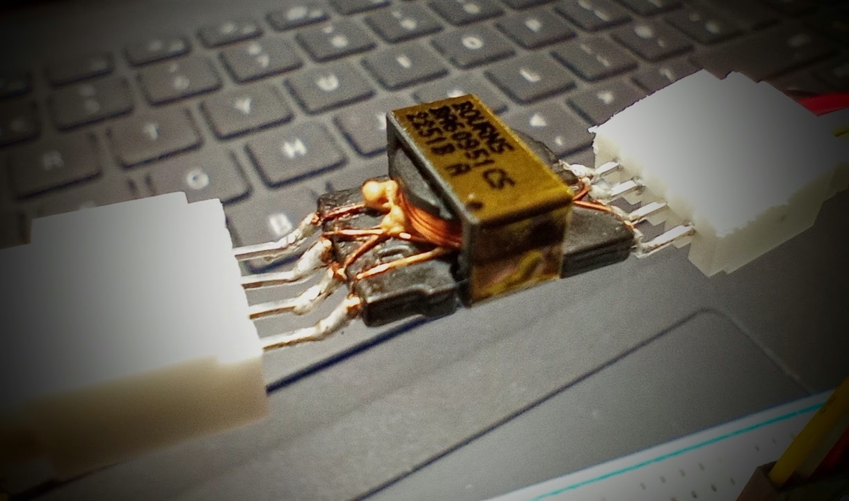
And, I’m sorry to say folks… yet again, I never had reporters and TV crew on hand to capture the event. So, you’ll just have to take my word for it. It was pretty spectacular.
So, here’s how I’ve started this design challenge journey.
First step - check my assumption for AC power operation
In my application I had requested the AC power supply to allow me to test out my AC options and I received a 24VAC power supply from IDEAL Power, which looks “ideal” for my purposes.
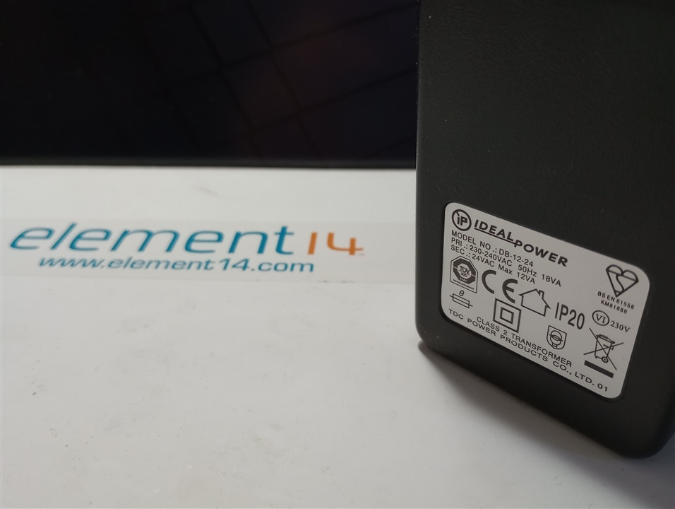
Now with AC voltage, I knew I would have to check for zero crossing and measure the timing in order to determine if there was a power failure. So as my first step I decided to check that I could reliably measure the zero crossing of an AC power supply.
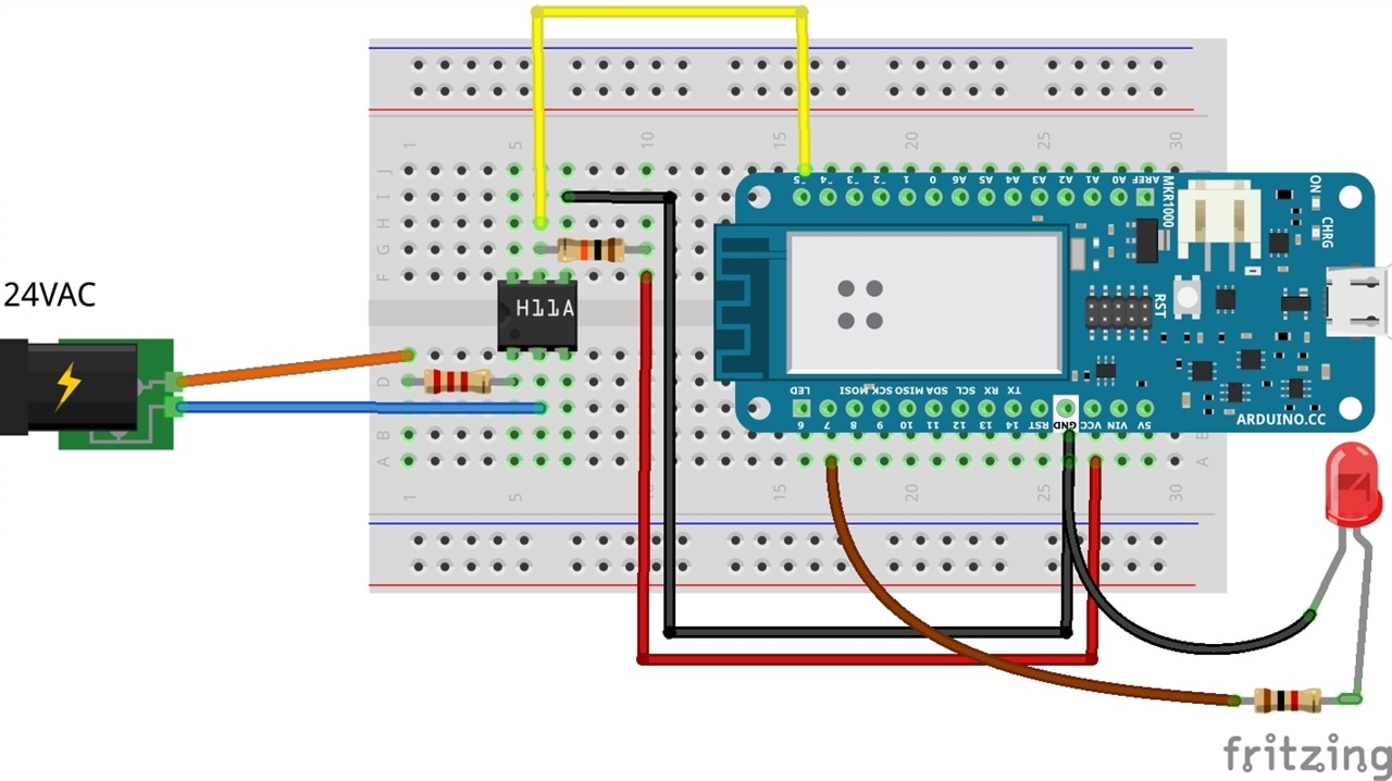
I knew optocouplers were commonly used for this purpose and when watching a video on YouTube I spotted a H11AA1 opto-coupler being used. This has a bi-directional input, making it suitable for applications requiring detection or monitoring of AC signals.
The circuit looked nice and simple to build:
And here’s my first video demo. As you might guess from the voice-over, this video was taken well before I had even tested a single flyback transformer…
Anyway, as far as I was concerned, this was the start I was looking for. It’s given me confidence to move forward on the AC side, and I now plan to test a number of the flyback transformers available in my kit to see how much power I will be able to get for my application.
Looking at the kit, I think I have quite a few to choose from.

Second step - check my assumption for DC power operation
Buoyed by the success of my zero crossing detection circuit, I then moved onto testing my assumptions of how I could use a SMPS flyback transformer with DC power.
For this experiment I used the BA60951CS flyback transformer provided in the kit.
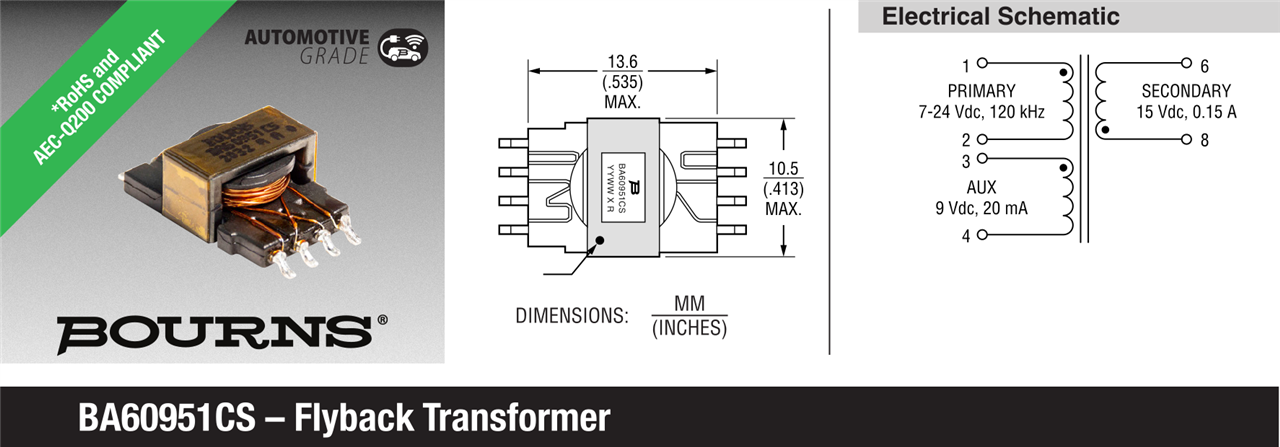
Reading through the general specifications provided in the datasheet, I could see that this flyback transformer accepts a primary input voltage between 7 to 24V, and based on the different turns ratios for auxiliary (1.27) and secondary (0.77) coils delivers an auxiliary voltage of approx. 9V and a secondary voltage of approx. 15V. What is not clear to me in the datasheet is this so-called “working voltage” of 800V, but as I have no plans to use really high voltages I will leave that as an open question.
There were also two other specifications where I was struggling to understand the context. Namely rated primary current (1.4A) and the frequency (120kHz).
So I decided to just try out a minimal circuit design that were shown in the beginners guides to flyback converters. Namely:
Figure 1 in the Coilcraft beginners guide...
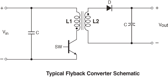
And figure 1 in the Kynix explanation on flyback transformers...

But, instead of using a MOSFET, I chose to use a momentary push button to manually/randomly control switching. Whilst I discovered that this option did not really work at all, it did reveal some interesting behaviour when you had debounce. It was slowly dawning on me as to why switching frequency matters, but this took a good deal of convincing.
I was still trying to understand the behaviour as described in the Coilcraft article:
The basic flyback cycle includes the following portions:
-
When the FET (Field Effect Transistor) SW is closed (ON), current is conducted through the transformer primary. This sets up a magnetic field in which energy is stored in the core. The combination of winding polarity (identified by the polarity dots) reverse biases the output diode to ensure that no energy is transferred to the secondary (load) when the switch is closed. During this portion of the cycle, current in the primary is ramping up over time to store energy (= ½LI2).
-
When the FET is opened (OFF) the magnetic field collapses, transferring the stored energy to the secondary winding and, ultimately the load. At the close of the switch, current in the secondary is at its peak and ramps downward as the stored energy is transferred to the load.
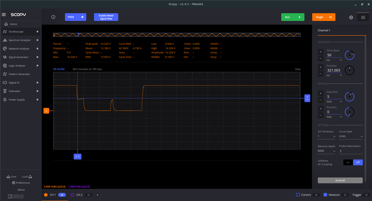
I somehow had thought that you could get the switch closed (ON) indefinitely. When testing, all I could see on my oscilloscope was that the primary voltage drops… as shown here when I momentarily keep the pushbutton on.
In fact, I was convinced it was circuit related. So, I then added a RCD snubber on the primary side, thinking this would solve matters. It did to some degree but not that much.
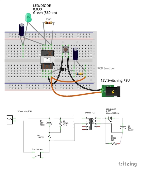
Here in my circuit I used an LED instead of a standard diode on the secondary side to help visualise matters (I relied on the fact that voltage and current flow was momentary).
I could now observe interesting behaviour during button debounce on the secondary side, as shown, but it still not help my understanding of the fundamental concepts when using DC power. This is the secondary voltage through the diode:
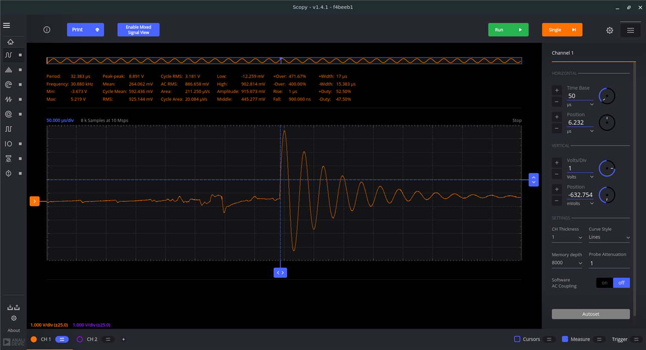
And this is the voltage across the capacitor (when there is no load - open circuit).
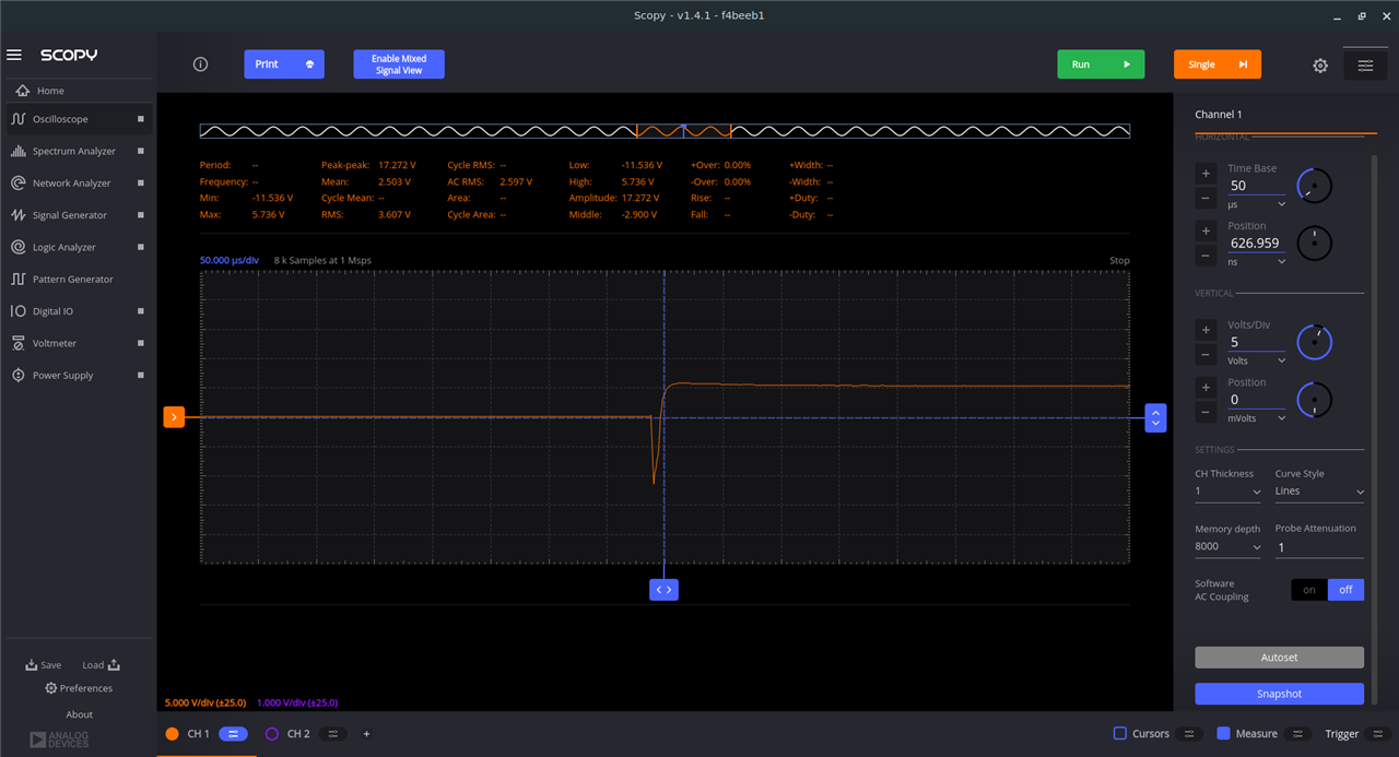
It still just did not make sense to me.
So, I took matters to the extreme, where I hooked up a 6A 15V power supply to the primary coil and held the switch on... and as mentioned in my introduction, this did not end well.
Anyway, I have finally grasped the meaning of “During this portion of the cycle, current in the primary is ramping up over time to store energy (= ½LI2)”.
And... I've also ordered another BA60951CS to continue.
Next steps
As to my next steps for this design challenge. Well, I am happy with AC but for DC I am now preparing a radical rethink of my design concept.
You’ll just have to wait till my next blog to find out…

Top Comments