In this blog, I will do two experiments using Automotive Grade DC-DC Flyback Transformer BOURNS BA60951CS and design
- Experiment 1 : BOURNS Solar Warning LED Driver
- Experiment 2 : BOURNS Solar Warning & Flashing LED Driver
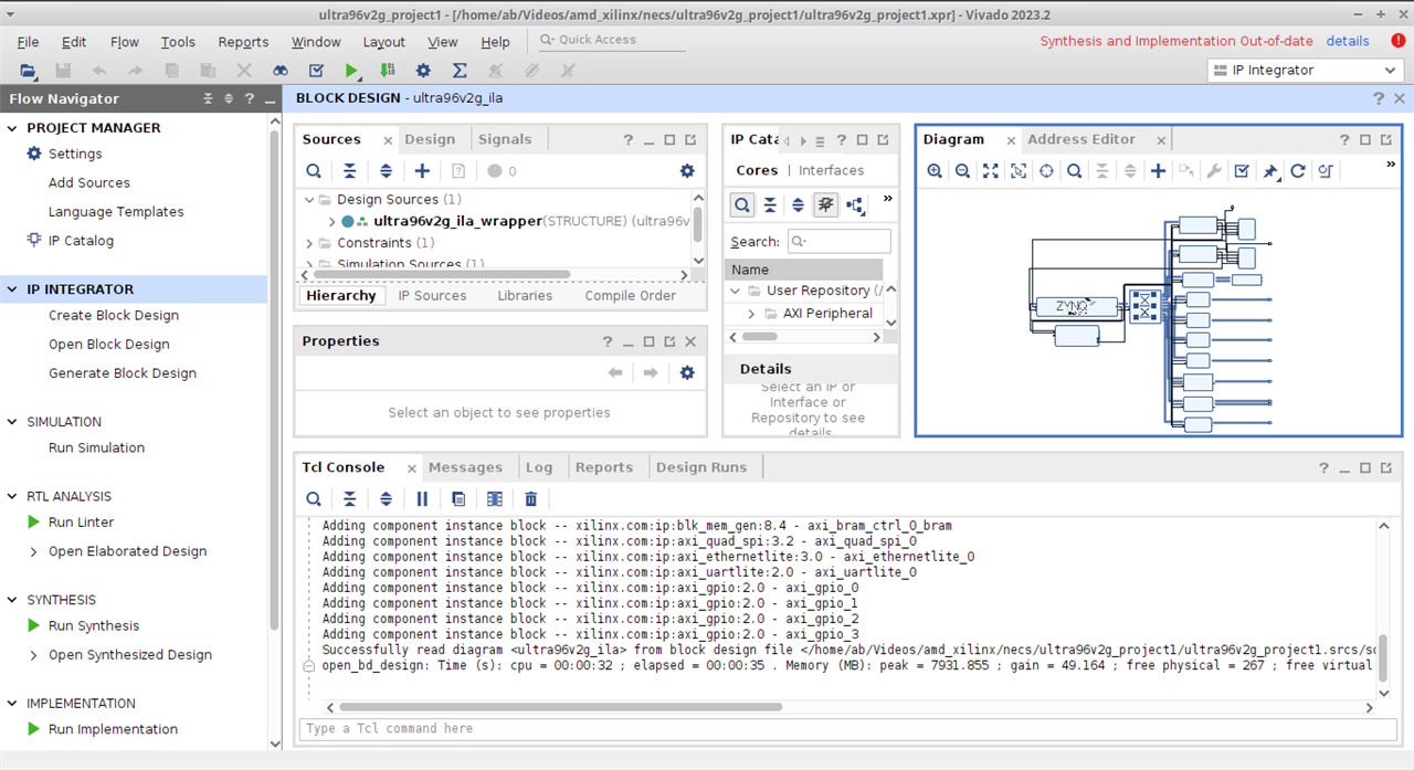
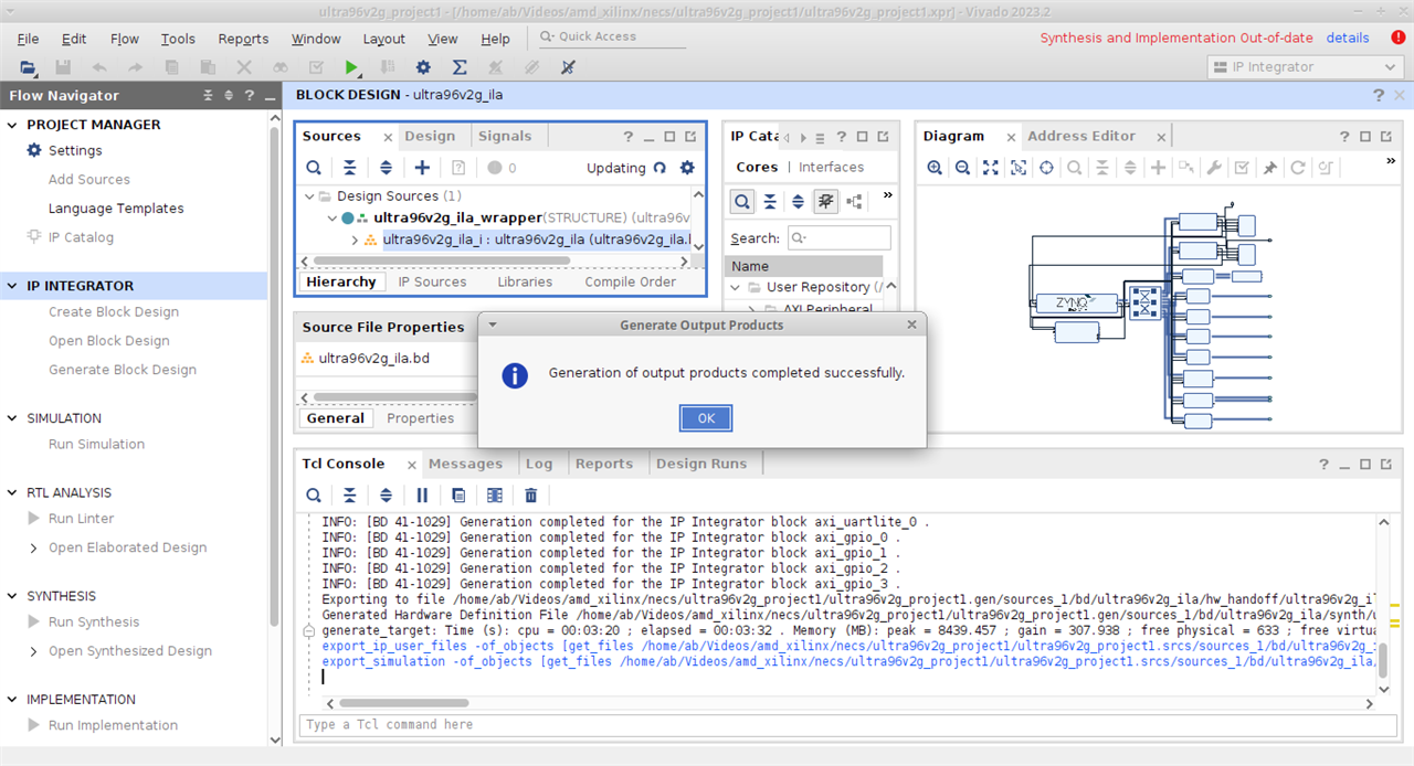
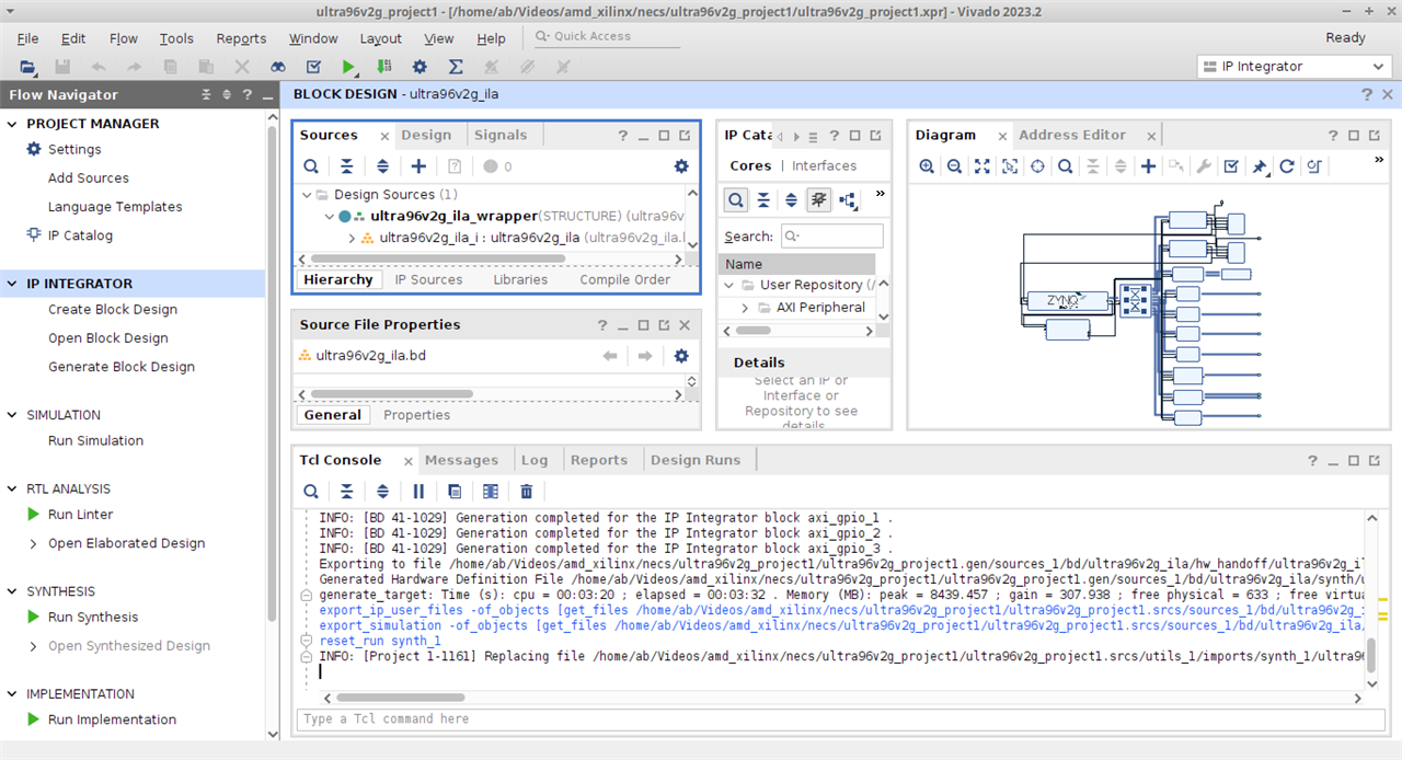
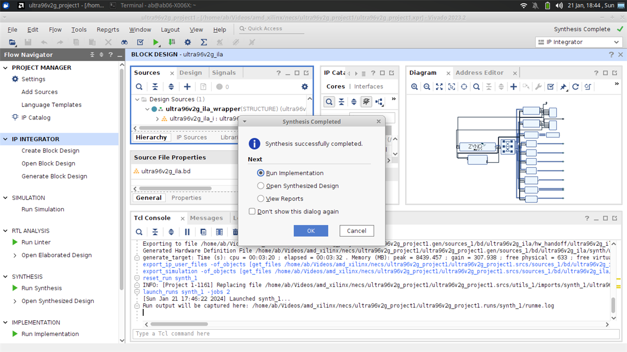
But before this experimentation, I will do setup of AVNET's FPGA MPSoC board as the BOURNS transformer will be drived using AES-Ultra96V2G and Click Mezzanine 96Boards. Then I will try polarity check, continuity check and measure resistances, inductances and capacitances using LCR meter.
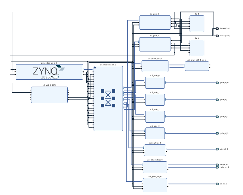
I. FPGA setup of AVNET Ultra96V2G
Vivado 2023. 2 is used.
1.1) Version 1
| {gallery}ultra96v2g |
|---|
 |
 |
 |
 |
1.2 ) Version 2
| {gallery}v2 |
|---|
 |
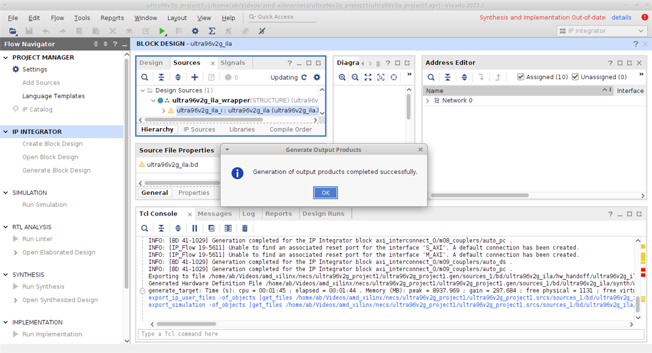 |
Note : This setup is same for blog 5 and for 'Final Blog'. The PWM custom IP version 2 is not used, replaced by version 3.
References
- Path to Programmable 3 Final Project : ILA, FEA, CFD, UltraScale+ Irrigation, Cryptography & Custom IPs
- Ubuntu/Linux USB AMD Drivers
- Solved:Linux/Ubuntu Installation stuck in Vivado/Vitis AMD
- PWM Version 3
II. Polarity Play & Endurance of BOURNS Transformers
What is Polarity Test
Polarity test determines terminals having the same instantaneous polarity. It is categorized by additive or subtractive polarity.
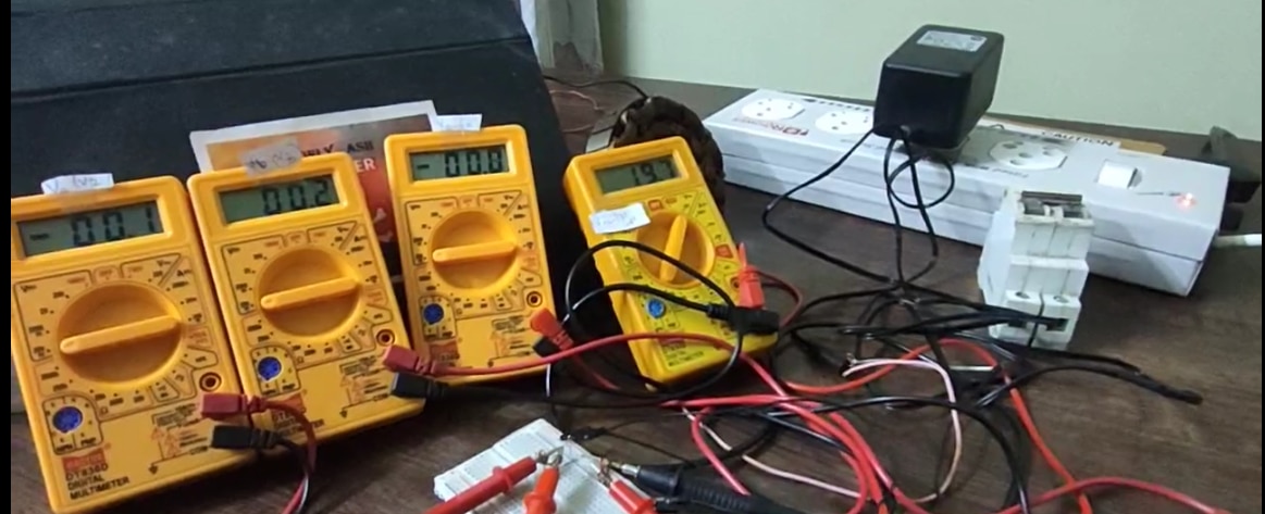
As the polarity test need a low voltage AC source, I have used IDEAL POWER, 77DE-10-15M, given with the kit sponsored by BOURNS. Using this AC-AC adapter, I achieved low voltage AC source as it steps down 230 VAC to 15 VAC.
As can be seen in videos, with no load, the output AC voltage is 20 VAC instead 15VAC. And with BOURNS transformer connected it is around 19VAC.
There was one short happened during testing and the VAC instead 15VAC or 19 VAC, fell to 13 VAC. But BOURNS transformers have endurance and after correcting the short, the IDEAL POWER adapter again gave 20VAC and 19VAC.
Generally, one do not connect AC to breadboard but I have connected this low voltage AC to breadboard!
I tried with all transformers except BOURNS gate drive and BOURNS DC-DC flyback transformer.
In all AC-DC Flyback transformers, the polarity test readings are similar in milllivolts or lesser or zero except common mode chokes.
This may be due to that these SMPS multi primary and multi-secondary transformers need higher than 19VAC or may be polarity test need to be carried out in different manner. I have 2 ideas to try but deadline of the contest is almost reached. Or may be this is used for linear transformers not SMPS transformers!
I have used 4 voltmeters, one voltage will read input AC voltae and the rest three the transformer readings.
The schematic used is
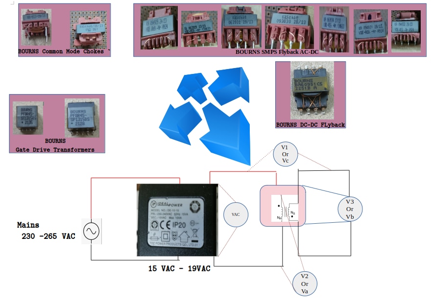
Result- I found polarity check not much useful because of very low readings (voltages are in decimals of a volt, in millivolts!) but used continuity checks to complete my experiments. May be polarity test is not meant for SMPS or may be it needs higher AC than I applied.
III. Continuity Play & Singing BOURNS Transformers
IV. Testing BOURNS Transformers with LCR
1. Gate Drive Transformer, PFBR45-ST13150S
This transformer has 4 pins in the primary and 4 pins in the secondary.
Though, this particular Gate Drive Transformer, PFBR45-ST13150S has physical pins 2, 3 but both are open and have neither any winding nor any connection.

1.1 Primary Inductance
Datasheet says the Primary Inductance at 100 kHz is 1 mH , + 35%, -30%.
Here I have measured Primary Inductance
- Pin 1-4 1.196 mH -1.2 mH
1.2 Secondary Inductance
- Pin 8-6 0.301 mH
- Pin 7-5 0.301 mH
1.3 Leakage Inductance
Datasheet says the Leakage Inductance is 1.5 μH - 2 μH.
Here I have measured Leakage Inductance, after shorting all secondary pins
- Pin 1-4 0.035 mH , 0.4 μH
1.4 DCR
- pin 1-4 0.3 Ω
- Pin 8-6 0.2 Ω
- Pin 7-5 0.2 Ω
1.5 Interwinding Capacitance
- Pin 1-4 63.1-64.6 μF
- Pin 8-6 25.7-26.2 μF
- Pin 7-5 25.7-26.2 μF
2. Gate Drive Transformer, PFBR45-SP13150S
This transformer has 5 pins in the primary and 4 pins in the secondary. here pin 7 is open and pin 3 also open

2.1 Primary Inductance
Datasheet says the Primary Inductance at 100 kHz is 1.15 mH , ± 30%.
Here I have measured Primary Inductance
- Pin 9-8 0.25 mH
- Pin 8-6 0.25 mH
- Pin 9-6 1.10 mH
2.2 Secondary Inductance
- Pin 1-4 mH
- Pin 2-5 0.288 mH
2.3 Leakage Inductance
Datasheet says the Leakage Inductance is 1.3 μH.
Here I have measured Leakage Inductance, after shorting all secondary pins
- Pin 9-8 0.026
- Pin 8-6 0.018 - 0.026
- Pin 9-6 1.153 mH
2.4 DCR
- Pin 9-8 0.3 Ω
- Pin 8-6 0.3 Ω
- Pin 9-6 0.5 Ω
2.5 Interwinding Capacitance
- Pin 9-8 21.2 - 22.6 μF
- Pin 8-6 21.2 - 22.6 μF
- Pin 9-6 54.8 - 56.2 μF
- Pin 1-4 22.6-24..3 μF
- Pin 2-5 22.6-24..3 μF
- Pin 1-5 0 μF
Conclusion : BOURNS Transformers are of very high quality, pins 1, 5 are not connected, i still checked and it is perfect 0 interwinding capacitance.
Moreover, one side pins where there is dual secondary, the readings are equal for both outputs.
Similary, where the primary is center tapped, the center-tap with each pin on the primary, the readings are same.
It was surprising the leakage inductance even fall below the datasheeet specs .
The primary inductance however, was not stationary, sometimes it was equal to the datasheet (no frequency applied), but sometimes was little lower or even higher than the data sheet.
Hence,BOURNS Transformers are of very high quality.
I have attached video recordings for 2 gate drive transformers, for rest I m not going as planned.
3. SMPS Flyback Transformer, BOURNS 094929
This transformer BOURNS 094929 has 4 pins in the primary and 4 pins in the secondary.
4. SMPS Flyback Transformer, BOURNS 063929
This transformer BOURNS 063929 has 4 pins in the primary and 4 pins in the secondary.
The last three digits of '929' this transformer 063 929 is same the last three digits of the previous transformer 094 929
5. SMPS Flyback Transformer, BOURNS 063932
This transformer BOURNS 063932 has 4 pins in the primary and 4 pins in the secondary but one pin is open in the primary and one pin is center-tapped.

6. SMPS Flyback Transformer, BOURNS 093830
This transformer BOURNS 093830 has 4 pins in the primary and 4 pins in the secondary.
7. SMPS Flyback Transformer, BOURNS 063934
This transformer BOURNS 063934 has 4 pins in the primary and 4 pins in the secondary.
8. SMPS Flyback Transformer, BOURNS 094931
This transformer BOURNS 094931 has 4 pins in the primary and 4 pins in the secondary.
9. SMPS Flyback Transformer, BOURNS 094932
Except the last digit, this transformer number is same the previous transformer; both transformers number is 094 43 X.
This transformer BOURNS 094932 has 4 pins in the primary and 4 pins in the secondary.
10. Common Mode Choke, 071923
This Common Mode Choke, 071923 has 2 pins in the primary and 2 pins in the secondary.
11. Common Mode Choke, 093267
This Common Mode Choke, 093267 has 2 pins in the primary and 2 pins in the secondary.
12. Automotive Grade DC-DC Flyback Transformer BOURNS BA60951CS
This transformer has 4 pins in the primary and 4 pins in the secondary but in the secondary, the physical pins 5, 7 are open and have neither any winding nor any connection.

V. General & Main Schematics
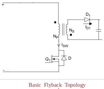
a )The basic flyback topology as you know is
The general schematic to run BOURNS DC- DC transformers is below, and BOURNS is compatible with all vendors!
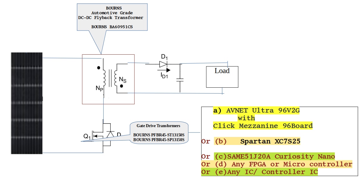
Fig. : General Schematic : BOURNS DC-DC Flyback Transformer, in conjunction with BOURNS gate drive transformer.
b) Connecting BOURNS Gate Drive transformers with BOURNS DC-DC Flyback
Bourns gate drive transformers can drive MOSFET with minimum of just 2 resistors and a capacitor. One resistor will be in parallel with Gate-Source.
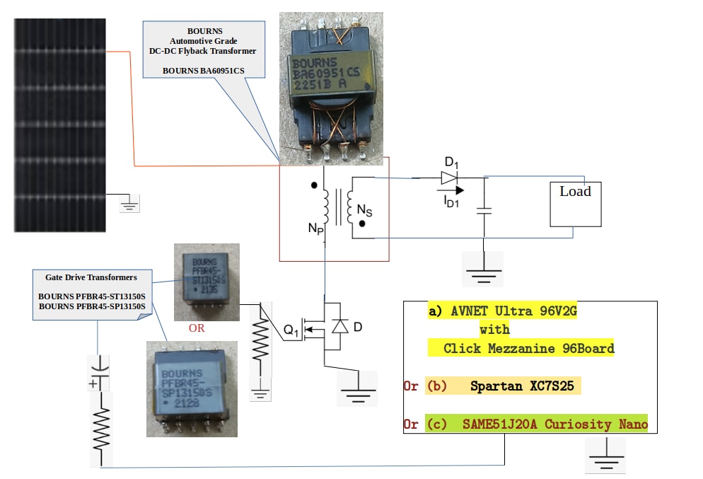
Fig. : Main Schematic for this Blog 4
Pls note that the FPGA board like AVNET Ultra96V2G need 12 V power supply but this won't be taken from using this DC-DC flyback transformer. For this blog, the power supply for FPGA board is AC-DC only not from the design.
VI. Experiments
Cautionary Note :
- The given transformers in the kit are used practically in a regulated power supply and due to not having an oscilloscope,and also limited R&D components or exact component values not on desk, the component's values I haven't mentioned (as these will change in implementation. Used ones will result in an inefficient circuit.)
- As I have mentioned in blog3- design example's video, the selection of components is not so simple, the experiments in blog 4, blog 5 and final blog are a play.
- Software code is eliminated as elementary.
- I have used word playing instead designing when shown a working system, because these circuits do not have protection and other mandatory circuits, before the circuit can be used for long run, and can be improved for better efficiency. But otherwise, the same whole circuit I will design for industrial or consumer scenarios
Experiment 1 : BOURNS Solar Warning LED Driver
Description
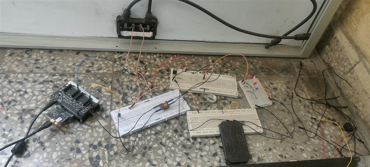
Warning Red LED Driver which gets input from 255 W solar panel and is driven using AVNET AES-Ultra96V2G and Click Mezzanine 96Boards
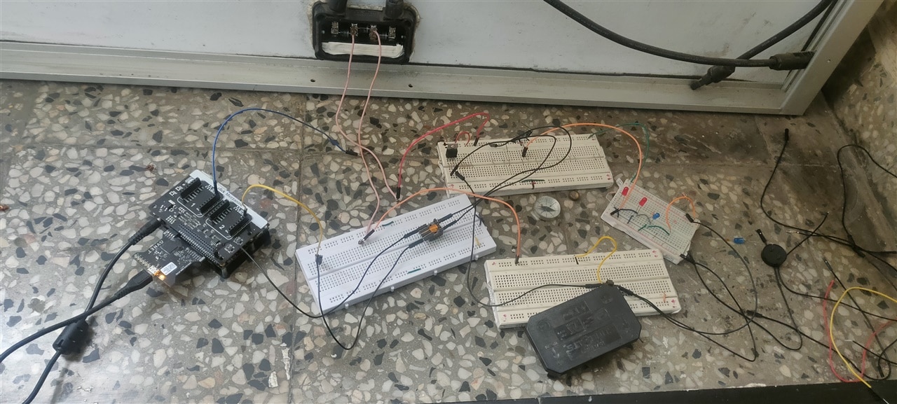
1) As this particular DC-DC Bourns transformer BA60951CS has very small pins, so firstly I modified pins of BOURNS BA60951CS by soldering
| {gallery}Circuit DC-DC |
|---|
 |
 |
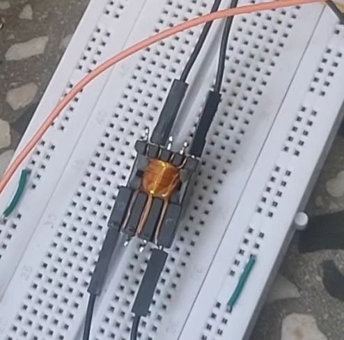
2) There are two gate drivers ,
- BOURNS PFBR45-ST13150S
- BOURNS PFBR45-SP13150S
But BOURNS PFBR45-ST13150S pins are much than this, so I used BOURNS PFBR45-SP13150S and connecters can be easily connected
3) Then I did set up using this schematic
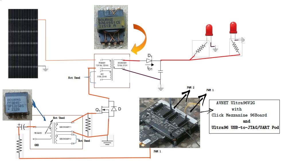
4) Result
Experiment 2 : BOURNS Solar Warning & Flashing LED Driver
Description
Warning Red LED Driver, blinking/flashing at multi-frequencies.
DC-DC BOURNS flyback transformer gets the Input directly from solar panel rated 255 W and drives the warning flashing LED is driven using AVNET AES-Ultra96V2G and Click Mezzanine 96Boards
After these 2 experiments,
Though BOURNS sponsored this DC-DC transformer in only one quantity, I still risked the DC-DC BOURNS flyback transformer by modifying the pins using solder and it was a bad idea. After this experiment, this is what happened
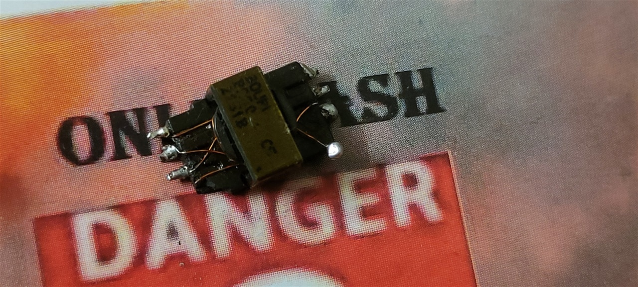
Both sides 1 pin damaged. On one side the pin came out with winding and for the other side, the pin got stuck in the connector.
but BOURNS transformer has endurance and this same piece of DC-DC transformer can be still used but only on PCB. And the other way could be soldering but not with solder wire (whichI used here), for which i dont have time to go to market but resoldering pins will make it work.
So, other planned experiments cant be executed.


Top Comments
-

shabaz
-
Cancel
-
Vote Up
+1
Vote Down
-
-
Sign in to reply
-
More
-
Cancel
-

jc2048
in reply to shabaz
-
Cancel
-
Vote Up
+1
Vote Down
-
-
Sign in to reply
-
More
-
Cancel
-

Jan Cumps
in reply to abhishek2018
-
Cancel
-
Vote Up
0
Vote Down
-
-
Sign in to reply
-
More
-
Cancel
-

abhishek2018
in reply to Jan Cumps
-
Cancel
-
Vote Up
0
Vote Down
-
-
Sign in to reply
-
More
-
Cancel
-

Jan Cumps
in reply to abhishek2018
-
Cancel
-
Vote Up
0
Vote Down
-
-
Sign in to reply
-
More
-
Cancel
-

jc2048
in reply to abhishek2018
-
Cancel
-
Vote Up
0
Vote Down
-
-
Sign in to reply
-
More
-
Cancel
-

Jan Cumps
in reply to jc2048
-
Cancel
-
Vote Up
0
Vote Down
-
-
Sign in to reply
-
More
-
Cancel
Comment-

Jan Cumps
in reply to jc2048
-
Cancel
-
Vote Up
0
Vote Down
-
-
Sign in to reply
-
More
-
Cancel
Children