Table of Contents
Introduction to ADC
Sometimes it is quite easy to think that programming an ADC(Analog to Digital converter) is so simple. Specially if someone is used to to the Arduino platform. In Arduino, it is quite simple with almost one line of code as following. But programming them can be challenging if we are using official Espressif programming environment like the ESP-IDF. That is because of number of configurations one has to define in the code. These configurations are kind of settings for specific ADC module in particular SoC.
analogRead(pin);
But as I said ADC are very important piece of hardware in Microcontroller. Internally, ADC have many separate hardware blocks within them. For example, ADC in ESP32-C6 have sample and hold, DMA interface, FIFO module, clock control and signals, etc. Following image shows internal structure of ADC in ESP32-C6. ESP32-C6 has only one ADC module but some devices such as ESP32 and ESP32-S3 have two or more ADC modules. As can be seen from the following figure multiple GPIOs can be used to read analog values.
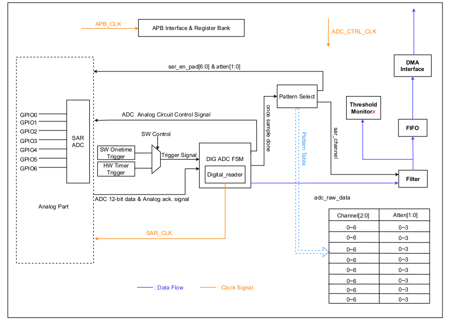
The focus of this tutorial is to provide with necessary steps to read analog values such as from sensors or external device on to the GPIO of ESP32-C6 device.
First, the installation of ESP-IDF should be done from Espressif website. The following commands shows how to check the version of esp-idf and set command environment to get started programming.
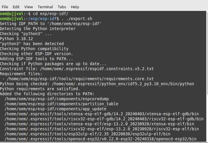
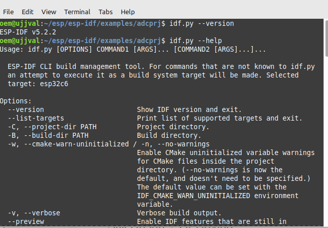
There are some important commands to know before actually start working with the esp-idf and ADC API.
$ idf.py set-target esp32c6 //To set the specific target SoC such as ESP32, ESP32s3, ESP32-S2, etc
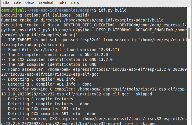
$ idf.py build //To build the project
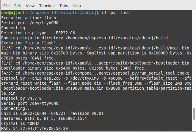
$ idf.py flash -p PORT //To flash the device
$ idf.py fullclean //clean the build
$ idf.py --help //help for available commands
To get started one can copy the template project located in /examples folder and edit the sample as per their requirements. I have created a separate project for the ADC by copying and modifying the available sample project.


First thing is to include the required header files in /main/main.c.
These files are required to work with ADC. In esp-idf, ADC have Continuous conversion mode and Oneshot mode drivers implementation. In continuous conversion mode, the device does conversion of the signal at predefined time while in Oneshot mode device do the conversion when we instruct it inside code to do so. This particular example is for Oneshot mode only.
#include <string.h>
#include "sdkconfig.h"
#include "esp_log.h"
#include "freertos/FreeRTOS.h"
#include "freertos/task.h"
#include "freertos/semphr.h"

#include "esp_adc/adc_continuous.h"
#include "esp_adc/adc_oneshot.h"
#include "hal/adc_types.h"

#include "esp_adc/adc_cali.h"
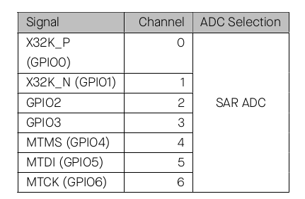
Next thing to decide is which GPIOs to use for the ADC. According to TRM of ESP32-C6 the following GPIOs are available for reading analog values. Remember that ESP32 uses strapping pins to upload code. These pins are used to sample the status of pin(either HIGH/LOW) at boot time to decide weather ESP32 will be in bootloader upload mode or in program execution mode. Some of the pins in below table are used as strapping pins for initial configuration of ESP32-C6. One should try to avoid these pins for ADC conversion. For ESP32-C6 the boot mode is controlled by GPIO 8 and 9.
Normally, if pin is not used for boot mode selection it is fine to use it for ADC as well. So from the below table we can use any pins for ADC conversion but GPIO4 and GPIO5 are used as strapping pins as well.
Copy and paste the following code to main.c inside the app_main() function. The code is for reading the analog values on a particular GPIO pin and convert these value using ADC parameters set by the user. These parameters are about configuring the particular ADC module, ADC channel/pin, ADC bit resolution, power mode selection, etc. By default the ADC uses it's internal reference voltage as the maximum output value for a GPIO sample value. This raw value must be converted to appropriate mV value. For that esp-idf has calibration API that one can use to convert raw value to proper mV value. The code below provides calibrated mV for ADC channel 4(GPIO4).
int adc_read0, adc_read1;
int mv_output;


adc_oneshot_unit_handle_t handle = NULL;

adc_oneshot_unit_init_cfg_t init_config1 = {
.unit_id = ADC_UNIT_1,
.ulp_mode = ADC_ULP_MODE_DISABLE,
};

ESP_ERROR_CHECK(adc_oneshot_new_unit(&init_config1, &handle));

adc_oneshot_chan_cfg_t config = {

.bitwidth = ADC_BITWIDTH_DEFAULT,
.atten = ADC_ATTEN_DB_12,
};

ESP_ERROR_CHECK(adc_oneshot_config_channel(handle, ADC_CHANNEL_0, &config));
ESP_ERROR_CHECK(adc_oneshot_config_channel(handle, ADC_CHANNEL_4, &config));

adc_cali_handle_t cali_handle = NULL;


adc_cali_curve_fitting_config_t cali_config = {
.unit_id = ADC_UNIT_1,
.atten = ADC_ATTEN_DB_12,
.bitwidth = ADC_BITWIDTH_DEFAULT,
};


ESP_ERROR_CHECK(adc_cali_create_scheme_curve_fitting(&cali_config, &cali_handle));

//adc_cali_handle_t cali_handle = NULL;

while(1)
{
ESP_ERROR_CHECK(adc_oneshot_read(handle, ADC_CHANNEL_0, &adc_read0));
ESP_ERROR_CHECK(adc_oneshot_read(handle, ADC_CHANNEL_4, &adc_read1));
printf("Adc channel-0 raw read result %d \n", adc_read0);
printf("Adc channel-1 raw read result %d \n", adc_read1);
printf("\n\n");
adc_cali_raw_to_voltage(cali_handle, adc_read1, &mv_output);
printf("ADC milivold output %d \n", mv_output);

vTaskDelay(100);
}
Build and Flash
For this tutorial one can use any ESP32 board or ESP32-C6 SoC based board. It is required to set the right target device we are building the code for using command $idf.py set-target
I am using DFRobot Firebeetle ESP32-C6 device.
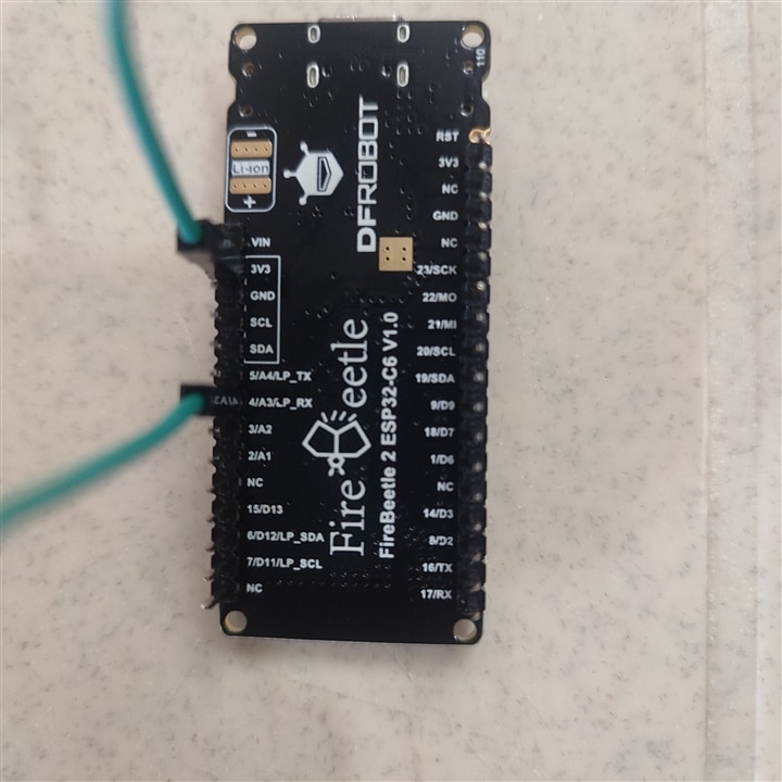
run $idf.py build to build the project.
use $idf.py flash to flash to the device.
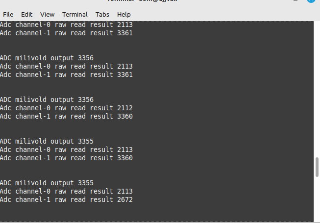
After flashing the following output should be visible. If you connect the GPIO to 3.3V line or GND, the output will change accordingly.
In the following I have attached the TRM(Technical Reference Manual) and code for the ADC one can flash on the board.
Finally, this is the end of this tutorial. I plan to write more such tutorials in the coming days.. Be it I2C, SPI peripherals, BLE device settings, DFU firmware update, camera module working, etc.
Stay tuned..!
Reference
