Introduction

In this blog I focus on the 3 DGH supercapacitors provided in the kit, namely:
- DGH105Q2R7: 1F 2.7 V
- DGH505Q2R7: 5F 2.7V
- DGH106Q2R7: 10F 2.7V
These DGH supercapacitors are specified as having a maximum voltage of 2.7V. So, with these supercapacitors I could not simply hook them up directly to a 3v3 power rail on a microcontroller. I needed a controlled power source.
So to start my tests, I focused on understanding charging behaviour and then I tested some RGB LED’s to gain some familiarity and these demonstrated some interesting characteristics.
Charging behaviour
To assist with my efforts I used my new ADALM2000 (M2K) Active Learning / USB-powered data acquisition module as it provided a programmable DC power source up to 5V via SCOPY (the desktop user interface).
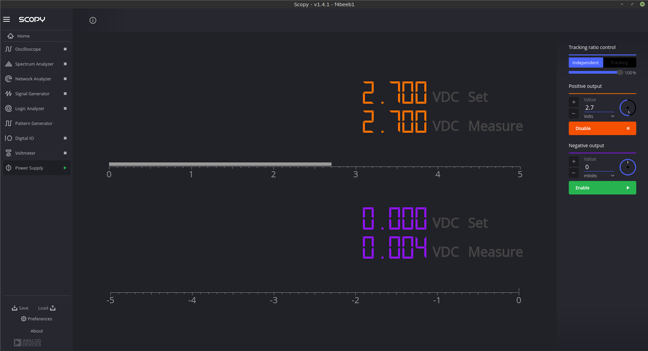
However, this power source can only source or sink a maximum of 58mA with the spec stating that it’s a 50mA power source; so it is not exactly quick. But the good thing is that with SCOPY I could capture data dynamically. For this, I used the voltmeter function.
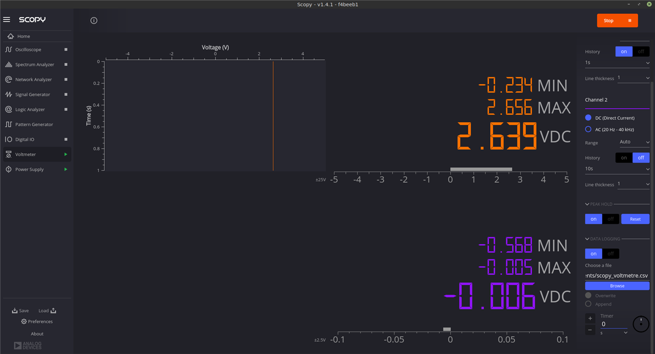
The outcome of these tests is that it demonstrated how the charging time differ by capacitance, with the 1F DGH105Q2R7 supercapacitor being the quickest to charge (approx. 1 minute) and the 10F DGH106Q2R7 taking the longest (>8 minutes).
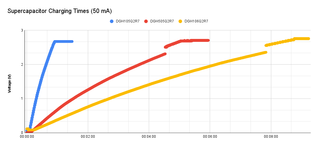
As these charging times were not suitable for my application, I had to figure out a much faster charging method as well as a simple way of dropping the voltage to approx. 2.7V.
I also wanted to move away from desktop programmable power supplies.
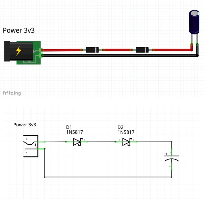
To this end, I decided to use a 1N5817 low drop power Schottky rectifier, which according to the spec, provides up to 1A of current and has a maximum forward voltage of 0.45V. In reality, the forward voltage is lower when less current is passing through, so I decided to use 2 of them, for good measure. This seemed to work as I got a max voltage of approx. 2.8V when charging the super capacitors (see charts below).
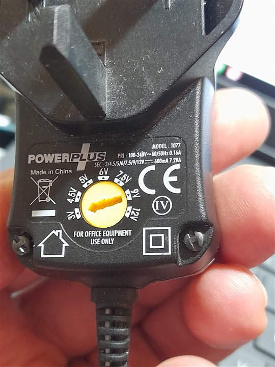
I also wanted something that provided more than 50mA. I grabbed the first power supply I could find, but actually this did not work very well. The larger supercapacitors would not reach their full charging level. Charging also took longer than expected. I did not investigate the reasons. I suspect there is probably a good, obvious reason for this behaviour.
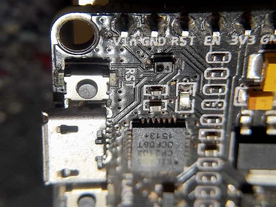
I then scratched around for an old dev board, as many of these provide a good solid 3v3 power source with a decent enough current. The one I used was an old ESP8266 NodeMCU board, which includes a AMS1117 low dropout voltage regulator. This did the job nicely (well to a point).
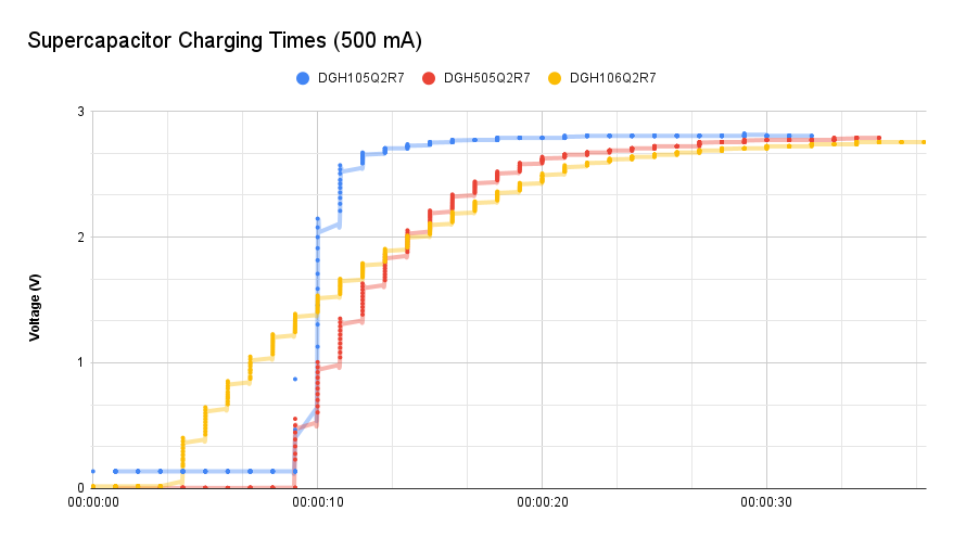
This delivered some perfectly acceptable charging times, with the 1F DGH105Q2R7 supercapacitor charged in a matter of seconds and the 10F DGH106Q2R7 approx. 30 seconds to achieve maximum charge.
However, when charging the DGH106Q2R7 supercapacitor I did spot a little white smoke coming from a diode. At least it proves a point about inrush currents and at least this was on a very old board that hadn't been used in years.
Powering some LED’s
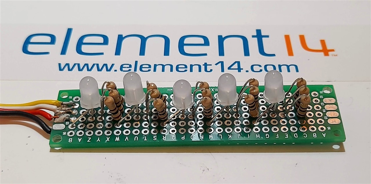
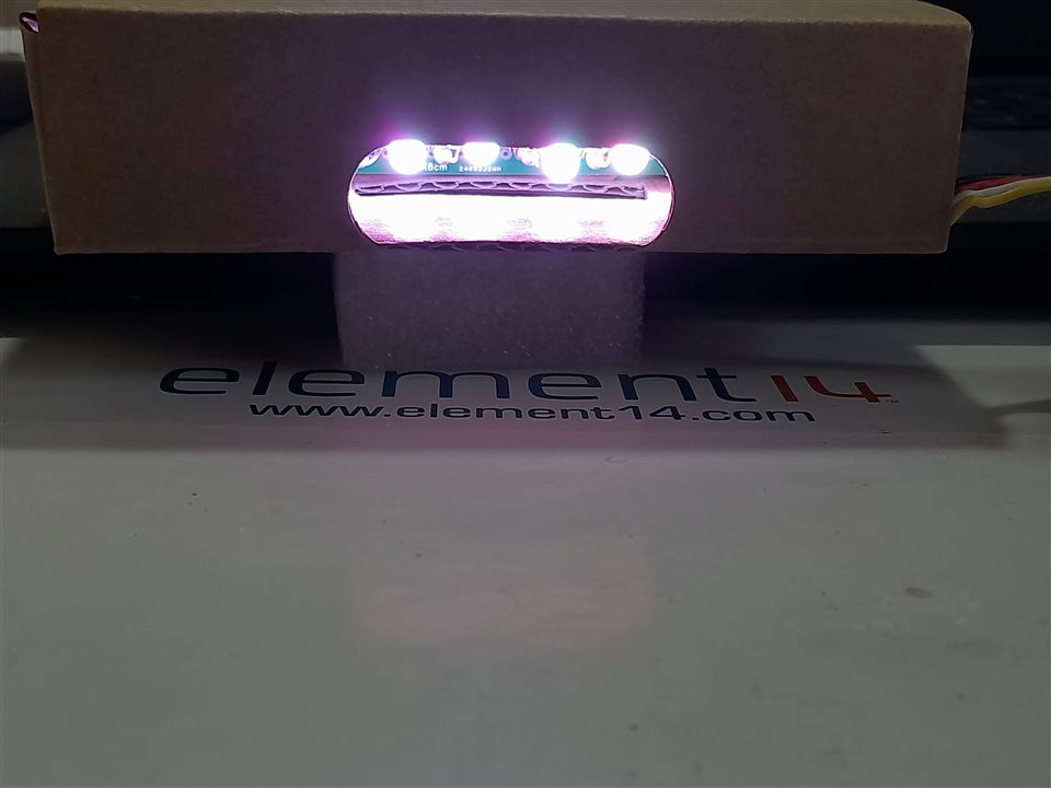
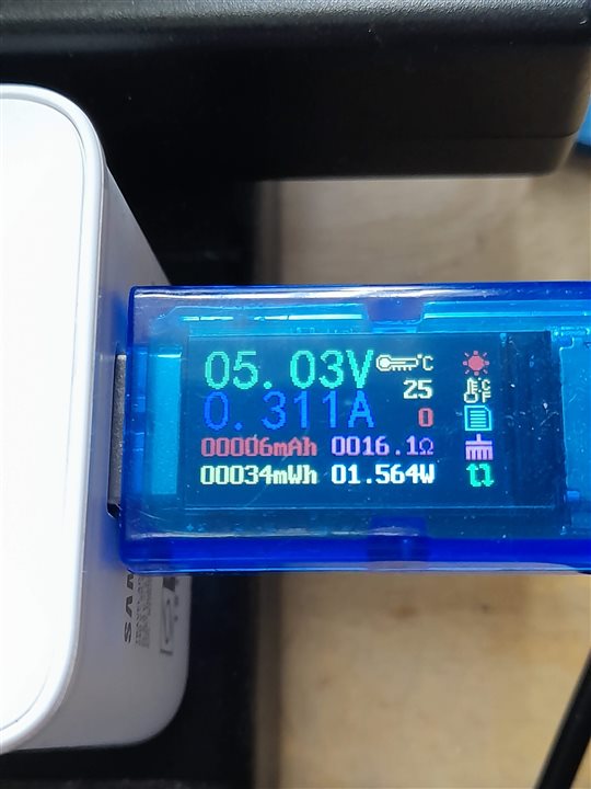
In a previous project of mine, I had used some 5mm ProSignal RGB common cathode through-hole 30mA LEDs to create a 5V USB powered LED board, which consumed 1.5W when all the LED’s were illuminated. This was as close to the maximum 30mA per LED as I could reasonably get.
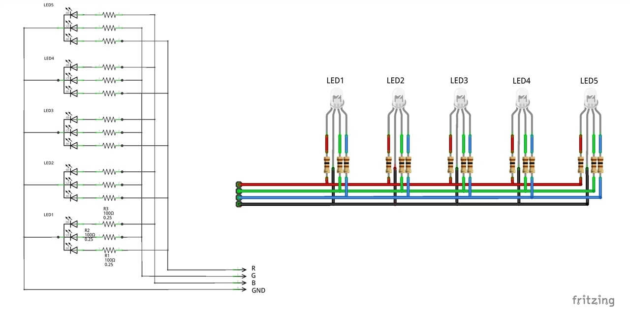
| {gallery:autoplay=false}LED Board powered by USB |
|---|
|
|
|
|
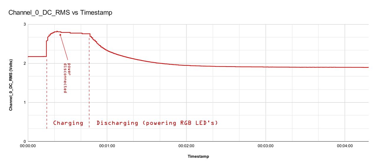
As this board was already made up, I decided to use this prototype board for my first LED experiment together with a 1F DGH supercapacitor (DGH105Q2R7) to learn what happens to the supercapacitor discharge rate. I was not disappointed with the results as it highlighted some unique behaviour.
Here is a video that captures the LED module in action (sorry there’s no audio).
As captured in the video, you can clearly see that there is no Blue LED as the supercapacitor's charged voltage is below the Blue LED's forward voltage. Then when the voltage gets close to and drops below the Green LED's forward voltage the Green LED dims and then turns off. Only the Red LEDs stay on, but these get dimmer.
What surprised me was how long the Red LED's remained on - I stopped the video recording after 4 minutes.
This experiment has helped me get some great insights, which I can now incorporate into my final design.
To be continued...

Top Comments