element14 Community
element14 Community
    Register Log In
  • Site
  • Search
  • Log In Register
  • Community Hub
    Community Hub
    • What's New on element14
    • Feedback and Support
    • Benefits of Membership
    • Personal Blogs
    • Members Area
    • Achievement Levels
  • Learn
    Learn
    • Ask an Expert
    • eBooks
    • element14 presents
    • Learning Center
    • Tech Spotlight
    • STEM Academy
    • Webinars, Training and Events
    • Learning Groups
  • Technologies
    Technologies
    • 3D Printing
    • FPGA
    • Industrial Automation
    • Internet of Things
    • Power & Energy
    • Sensors
    • Technology Groups
  • Challenges & Projects
    Challenges & Projects
    • Design Challenges
    • element14 presents Projects
    • Project14
    • Arduino Projects
    • Raspberry Pi Projects
    • Project Groups
  • Products
    Products
    • Arduino
    • Avnet & Tria Boards Community
    • Dev Tools
    • Manufacturers
    • Multicomp Pro
    • Product Groups
    • Raspberry Pi
    • RoadTests & Reviews
  • About Us
    About the element14 Community
  • Store
    Store
    • Visit Your Store
    • Choose another store...
      • Europe
      •  Austria (German)
      •  Belgium (Dutch, French)
      •  Bulgaria (Bulgarian)
      •  Czech Republic (Czech)
      •  Denmark (Danish)
      •  Estonia (Estonian)
      •  Finland (Finnish)
      •  France (French)
      •  Germany (German)
      •  Hungary (Hungarian)
      •  Ireland
      •  Israel
      •  Italy (Italian)
      •  Latvia (Latvian)
      •  
      •  Lithuania (Lithuanian)
      •  Netherlands (Dutch)
      •  Norway (Norwegian)
      •  Poland (Polish)
      •  Portugal (Portuguese)
      •  Romania (Romanian)
      •  Russia (Russian)
      •  Slovakia (Slovak)
      •  Slovenia (Slovenian)
      •  Spain (Spanish)
      •  Sweden (Swedish)
      •  Switzerland(German, French)
      •  Turkey (Turkish)
      •  United Kingdom
      • Asia Pacific
      •  Australia
      •  China
      •  Hong Kong
      •  India
      •  Japan
      •  Korea (Korean)
      •  Malaysia
      •  New Zealand
      •  Philippines
      •  Singapore
      •  Taiwan
      •  Thailand (Thai)
      •  Vietnam
      • Americas
      •  Brazil (Portuguese)
      •  Canada
      •  Mexico (Spanish)
      •  United States
      Can't find the country/region you're looking for? Visit our export site or find a local distributor.
  • Translate
  • Profile
  • Settings
Forget Me Not Design Challenge
  • Challenges & Projects
  • Design Challenges
  • Forget Me Not Design Challenge
  • More
  • Cancel
Forget Me Not Design Challenge
Blog Forget Me Not Challenge Design Challenge Post 08: Soldering Iron Monitor
  • Blog
  • Forum
  • Documents
  • Files
  • Events
  • Mentions
  • Sub-Groups
  • Tags
  • More
  • Cancel
  • New
  • Share
  • More
  • Cancel
Group Actions
  • Group RSS
  • More
  • Cancel
Engagement
  • Author Author: p-brane
  • Date Created: 22 Oct 2014 2:33 PM Date Created
  • Views 3777 views
  • Likes 0 likes
  • Comments 26 comments
  • forget_me_not
  • stm332u
  • temperature
  • enocean
  • energy_harvesting
  • iot_victorian
  • soldering
  • wireless
  • sensor
Related
Recommended

Forget Me Not Challenge Design Challenge Post 08: Soldering Iron Monitor

p-brane
p-brane
22 Oct 2014

Other Blogs in this project

Forget Me Not Design Challenge Week 01: The Introduction

Forget Me Not Design Challenge Week 02: The EnOcean Sensor Kit, EnOcean Pi, and Raspberry Pi Model B+ Unboxing

Forget Me Not Design Challenge Posting 03: The EnOcean Sensor Kit, EnOcean Pi, and Raspberry Pi Model B+ Setup, Configuration, and FHEM Operation

Forget Me Not Design Challenge Week 04: Tektronix TBS1052B-EDU Oscilloscope

Forget Me Not Design Challenge Post 05: EnOcean EOP-350 Universal Programmer Board

Forget Me Not Challenge Design Challenge Post 06: Cadsoft Eagle Schematics

Forget Me Not Challenge Design Challenge Post 07: Door Lock Monitor

Forget Me Not Challenge Design Challenge Post 09: Soil Moisture Monitor

Forget Me Not Challenge Design Challenge Post 10: Cat Feed Monitor

Forget Me Not Challenge Design Challenge Post 11: Project Summary


Overview

My original proposal for the soldering iron monitor using a k-type thermocouple mounted on a ceramic washer that was screwed into the soldering iron stand with a ceramic screw connected to a STM-332U Temperature Sensor Module is shown in Figure 1. Testing and blogging about the STM-332U revealed that using a k-type thermocouple without a thermocouple amplifier would not be practical. The output voltage from a k-type thermal couple would only produce about 4 mV at 100 °C. The analog inputs of the STM-332U are 8 and 10 bits, so sensitivity would not be very good [1]. I also could not find a thermocouple amplifier that would operate on 1.8 V that is produced by the sensor module for external circuits.
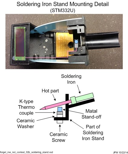
 

image

Figure 1


Design Update

Therefore, the k-thermocouple was replaced with a 10k Ohm NTC Thermistor and a 10k Ohm resistor connected together to form a resistor divider. Testing also showed that a stand-off in proximity to a hot soldering iron did not get hot enough to clearly indicate that the iron was on. A 14 gauge copper wire connected to the thermistor was added and configured to touch the soldering iron near the handle. The copper wire would conduct the heat from the soldering iron to the thermistor and provide a robust indication that the iron was on. The modifications to my original proposal are shown in Figure 2.
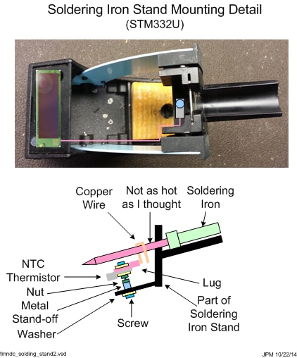
 

image

Figure 2


Figure 3 shows the thermistor mounting hardware in detail. I tried to get the thermistor as close to the soldering iron as possible using a combination of screws, nuts, stand-offs, and washers that were in stock at Newark.com. I used the smallest hardware available to keep the “thermal mass” as low as possible so that temperature measurement would be as quick as possible. It turned out that M3 hardware was the most available at the time of my order. I used 14 gauge copper wire that I stripped out of some home electrical wire I had on hand for the wire to contact the soldering iron.


A longer stand-off would have made the assembly easier as there was not much thread depth for the screws on each side. I added a nut to keep the stand-off tight, and another one to keep the thermistor and wire attached to a lug tight.
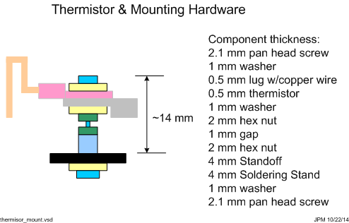
 

image

Figure 3


Thermistor

I selected an EPCOS NTC Thermistor part number B57703M103G40 because it had a lug for mounting and had a 10k Ohm resistance at 25 °C [2] [3]. Also, EPOS makes very high quality components (past experience with some of inductors). Figure 4 shows the resistance verses temperature (blue trace) and the digital value that the STM-332U would generate from the resistor divider at the analog input ADIO0 for a given temperature (green trace). NTC thermistors have an exponential relation with temperature [4] so the plot for resistance is semi-log to provide more detail at higher temperatures.
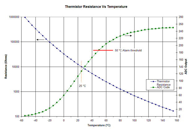
 

image

Figure 4

Soldering Stands

Figure 5 shows the modifications to the left and right soldering stands.
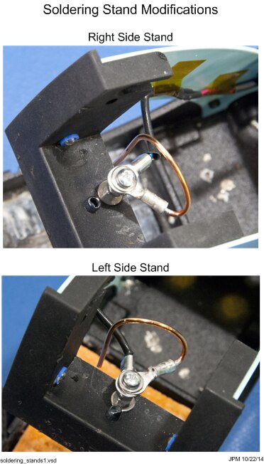
 

image

Figure 5


Temperature Sensor Configuration

Two STM-332U sensors were configured as temperature sensor, set point, and occupancy control using DolphinStudio and the EOP-350 Universal Programming Board (UPB), as shown in Figure 6.
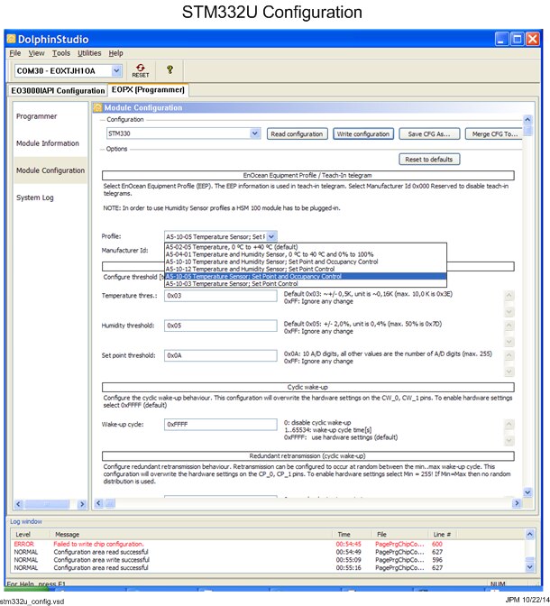
 

image

Figure 6


Temperature Sensor Modifications

These STM-332U sensors were modified to add the resistor and thermistor to form a resistor divider between ground and the switch power output SWPWR. The center tap of the resistor divider is connected to analog input ADIO0. An illustration of these connections is shown in Figure 7.
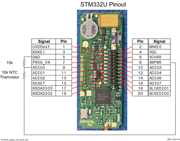
 

image

Figure 7


I was planning on using a mating connector (Samtec SFMC-110-01-L-D) to attach the resistor and thermistor to, but the connectors have not arrived yet so I soldered them directly to the boards. The spacing between ground and ADIO0 is just about the length of a 1206 size resistor. So I solder a 10k Ohm 1206 size resistor between these pins at the base of the connector (see Figure 8). Fortunately, I had some from another hobby project.


I cut up some female-female jumpers and used them to make an impromptu connector for the thermistor. The two wire assemblies were soldered to ADIO0 on top of one of the 10k Ohm resistor pads and to the SWPWR pad. I used hot glue to hold the wires in place and provide some strain relief. These modifications would still allow the STM-332U to be plugged in to the EOP-350 UPB, if they require new or further configuring.
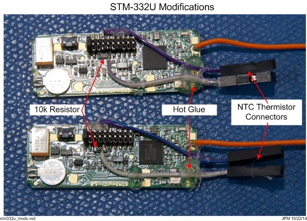
 

image

Figure 8


Figure 9 shows the modified STM-332U sensors connected to the thermistor on the soldering stand. The top photo in Figure 9 shows the soldering iron and how it contacts the copper wire.
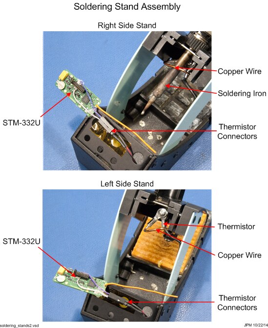
 

image

Figure 9


Figure 10 shows the modified STM-332U sensors set in place and the FHEM output can be seen showing the temperature (19 °C) and the set point of 109.
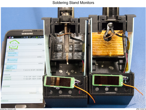
 

image

Figure 10


Soldering Iron Monitor Operation

Figure 11 shows the whole setup with both soldering irons and stands, the modified temperature monitors, and a DMM with a thermocouple to measure the thermistors before the soldering irons are turned on. FHEM shows that both sensors are reporting 19 °C and the set point of 110. The 110 reading corresponds to about 20 °C from the green plot in Figure 4.
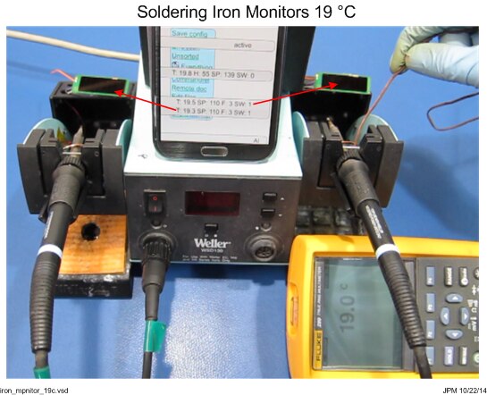
 

image

Figure 11


The left soldering iron is turned on, and after a while the thermistor reaches about 60 °C and the sensor shows the ADC output of 213 (see Figure 12). This value corresponds to about 65 °C from the green plot in Figure 4.
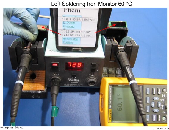
 

image

Figure 12


The left soldering iron was unplugged and the right one was plugged in. The right side soldering reached a temperature of about 48 °C and the right side sensors shows an ADC reading of 194. This corresponds to a temperature of about 53 °C from the green plot in Figure 4. The left side station was cooling while the right side heated to be values shown and reached an ADC reading of 167 or about 38 °C using the green plot in Figure 4.
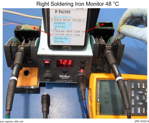
 

image

Figure 13


Summary

There seems to be a 5 °C or so error between what the sensors report and what I measured. The thermocouple and DMM measurement were slow and it took a while for the thermocouple to measure a temperature. It also kept slipping off the thermistor, so this may have contributed to the error. The plot in Figure 4 uses resistance verses temperature from the datasheet and does not take into account component tolerance variations, which would also contribute to some of the error measured. Even with these errors, the monitor show that the irons are operating. An effective alarm could be built in FEM or OpenHAB using rising and falling temperature slopes, room temperature iron temperature differentials, and a threshold of about 50 °C.


Video

You don't have permission to edit metadata of this video.
Edit media
x
image
Upload Preview
image


References

[1] EnOcean, Scavenger Transmitter Module STM 330 / STM 331 / STM 330C / STM 332U / STM 333U User Manual V1.20

[2] EPCOS, NTC Thermistors for temperature measurement, B57703M

[3] EPCOS, NTC Temperature Measurement Sensors

[4] EPCOS, NTC Thermistors General technical information

  • Sign in to reply

Top Comments

  • michaelwylie
    michaelwylie over 11 years ago in reply to ipv1 +2
    If you just need an iron, I got this one for the Forget Me Not challenge; http://www.newark.com/tenma/21-10115/soldering-station-esd-safe-60w/dp/56T2208 I'm thoroughly pleased with it, but you do need…
  • jw0752
    jw0752 over 11 years ago +1
    This is a very well done project and shows the scientific approach to solving a problem. John
  • mcb1
    mcb1 over 11 years ago +1
    Very nice. I do like the measurement of Temperature v ADC ... it ensures you know what to expect. I tried a similar setup for measuring light, but for some reason mine didn't work. I might need to go back…
  • p-brane
    p-brane over 11 years ago in reply to michaelwylie

    Hi Michael,

    That soldering iron looks like a great value. I have never understood why soldering stations are so expensive. I bought the Weller soldering station with two irons so that I could remove surface mount devices (resistors, caps, diodes etc). These have typically been 1206 or 0805 size and it took a little practice to wield two irons but its becomes easy to remove parts without damaging pads. What do you use or do to replace these type of devices with a single iron?

    • Cancel
    • Vote Up 0 Vote Down
    • Sign in to reply
    • More
    • Cancel
  • michaelwylie
    michaelwylie over 11 years ago in reply to ipv1

    I'm not planning on it! hah. I just like the challenge.

    • Cancel
    • Vote Up +1 Vote Down
    • Sign in to reply
    • More
    • Cancel
  • mcb1
    mcb1 over 11 years ago in reply to michaelwylie

    That looks like a very nice iron, and a nice price.

    We don't seem to have it in the Aust/NZ website, so I might need to go hunting in the UK and Singapore site.


    Thanks for sharing.

    Mark

    • Cancel
    • Vote Up 0 Vote Down
    • Sign in to reply
    • More
    • Cancel
  • ipv1
    ipv1 over 11 years ago in reply to michaelwylie

    Hopefully if you win here, then you get a better meter image

    • Cancel
    • Vote Up 0 Vote Down
    • Sign in to reply
    • More
    • Cancel
  • michaelwylie
    michaelwylie over 11 years ago in reply to fvan

    Yeah I got some different tips. I haven't tried the really small tips yet. That's usually where the cheaper irons don't work so well. If you can afford them, Metcal make the best irons.


    Also, as part of the budget I got a Tenma multimeter, and I would not recommend it. It's this one. I got it because it was like 50% off. Why do I not like it?

    1. The continuity checker lags.
    2. There doesn't seem to be a way to turn off the beeping. It beeps every time you do anything.
    3. The fold out stand on the back is very hard to pull out and then it slants too far.
    • Cancel
    • Vote Up 0 Vote Down
    • Sign in to reply
    • More
    • Cancel
<>
element14 Community

element14 is the first online community specifically for engineers. Connect with your peers and get expert answers to your questions.

  • Members
  • Learn
  • Technologies
  • Challenges & Projects
  • Products
  • Store
  • About Us
  • Feedback & Support
  • FAQs
  • Terms of Use
  • Privacy Policy
  • Legal and Copyright Notices
  • Sitemap
  • Cookies

An Avnet Company © 2026 Premier Farnell Limited. All Rights Reserved.

Premier Farnell Ltd, registered in England and Wales (no 00876412), registered office: Farnell House, Forge Lane, Leeds LS12 2NE.

ICP 备案号 10220084.

Follow element14

  • X
  • Facebook
  • linkedin
  • YouTube