

Table of contents

Abstract
Fusing AI vision with ultrasonic ranging improving the perception. By adding precise distance data to classified objects, addresses the vision failures in tough conditions and provides better environmental awareness.
Project
Introduction
Problem to be solved....
Traditional vision-based systems struggle in tough environments. Poor lighting, transparent or reflective objects, and visual obstructions limit their effectiveness. Relying only on cameras reduces detection accuracy in situations like low-light navigation and fog. This creates safety risks and operational challenges for robotics and autonomous systems.
Motivation
The need for dependable perception systems that function well in various environmental conditions led for the implementation of the EchoVision. By merging visual and ultrasonic sensing, the shortcomings of each technology can be addressed to a certain extent. Cameras offer rich visual information while ultrasonic sensors provide accurate distance measurements, regardless of lighting or surface type. This combination gives us a better understanding of the environment.
Why EchoVision..?
Echo Vision combines camera-based vision with ultrasonic distance sensing on the KR260 platform. This approach ensures reliable object detection and distance measurement in situations where single-sensor systems struggle. The outcome is a more dependable perception system suitable for real-world robotics applications, such as indoor navigation, obstacle avoidance, and assistive technologies, where environmental reliability is essential.
Compared to stereo camera systems, Echo Vision has some advantages. It needs far less computational power(for ranging) since the TDK's USSMs direct distance measurements without complex depth calculations. It works well in low-light conditions, on smooth surfaces, and with transparent objects where stereo vision fails. It is also more cost-effective(in terms of computational resources) and mechanically simpler, with no need for precise dual-camera calibration. Additionally, it delivers faster and more predictable response times, which are critical for real-time robotics. Most importantly, the sensor fusion approach combines visual details with reliable distance data, creating a stronger system than stereo vision alone.
Unboxing the Kit
There's a special kind of excitement that comes with opening a box of brand-new, high-quality hardware and TDK did not disappoint.
The kit arrived securely packaged, with each component neatly nestled in its own protective packaging. TDK's focus on a smooth start is also evident. Right on the packaging, helpful QR codes are provided, instantly linking to the datasheets and guides needed to dive right in.
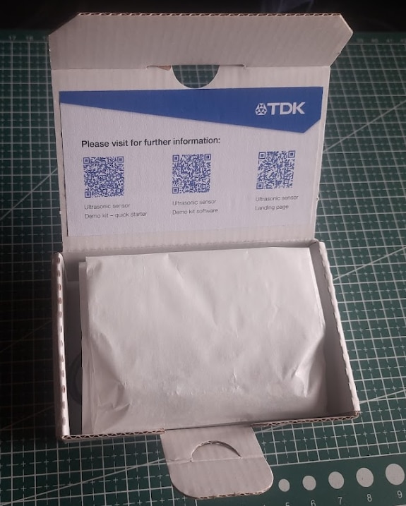
Before I even got to the hardware, I was immediately impressed by the packaging. It's clear TDK has prioritized sustainability, using eco friendly and biodegradable materials for the main insert. The only plastic in sight was the essential anti static bag protecting the demo board, a necessary measure. In an industry often dominated by single-use plastics, this thoughtful approach is something to be applauded!
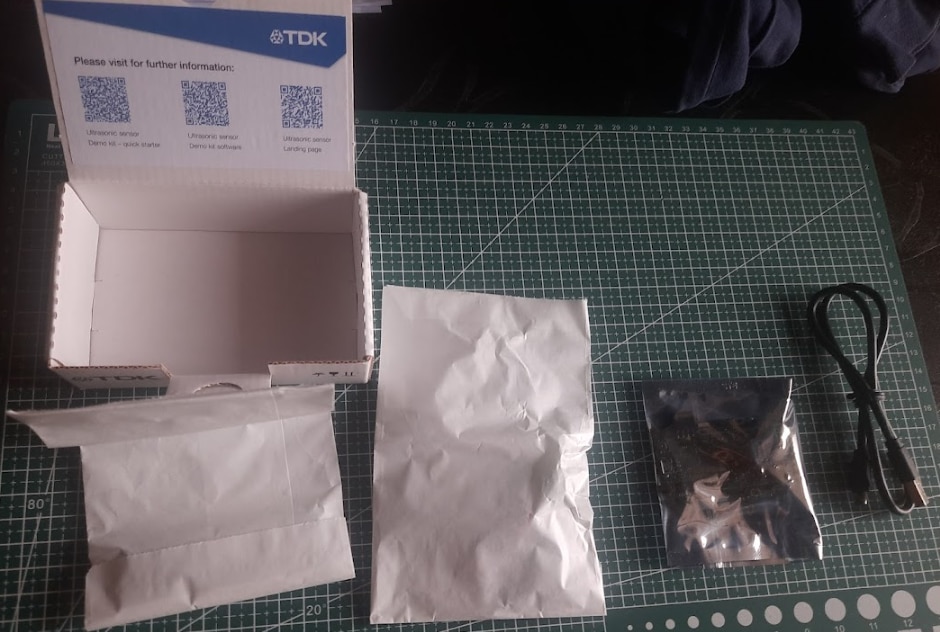
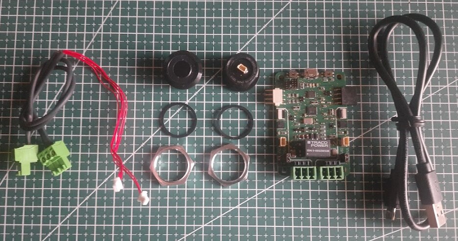
Inside the box, I found 2x sensor connection cables, 2x USSM1.0 PLUS-FS ultrasonic sensor along with it's locking nut and rubber gasket, 1x TDK USSM Demo Board and 1x Micro-B to USB A cable.
Hardware Deep-Dive of the Kit
Now that everything is out of the box, let's go beyond the surface and dive into the hardware and it's specifications.
TDK USSM1.0 PLUS-FS Ultrasonic Sensor
The core component of this challenge is the USSM1.0 PLUS FS ultrasonic sensor module. It is a self-contained piezo based sensor unit with an integrated Application Specific Integrated Circuit (ASIC), the E524.33 (IC's document is linked in the Resources section of the sensor's product page but not specified explicitly in the documentation of the sensor) that handles the ultrasonic signal processing internally.
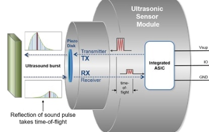
The principle of operation is Time of Flight (ToF), which is a method for measuring distance by precisely timing the journey of a wave. The process is as follows:
- Transmission: The sensor emits a short, high frequency burst of sound (an ultrasonic pulse of frequency of 74.5 KHz) into the air.
- Propagation: This sound wave travels outwards from the sensor at the speed of sound (c).
- Reflection: When the wave encounters an object, it reflects off the surface, creating an echo that travels back towards the sensor.
- Reception: The sensor's piezoelectric element detects the faint returning echo.
- Calculation: The integrated ASIC measures the total elapsed time (T) from the moment the pulse was transmitted to the moment the echo was received.
Because the sound wave traveled to the object and back, the one way distance (L) is half of the total distance traveled.
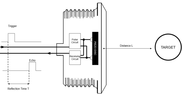
This relationship is defined by the fundamental ToF formula:
L = (c * T) / 2
The E524.33 is responsible for managing this entire sequence, from generating the driver signal for the burst to amplifying and filtering the received echo and performing the time measurement. This high level of integration simplifies the end application significantly, as the module provides reliable data without requiring complex external signal conditioning circuitry.
According to the technical datasheet, the sensor exhibits robust performance characteristics.
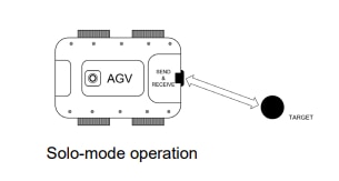
In its standard "solo mode," where a single sensor handles both transmission and reception, it features an operating range from 18 cm to 5 m.
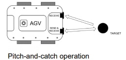
And the module also supports a "pitch and catch mode," which utilizes two sensors (one as emitter, one as receiver) to achieve a significantly reduced minimum detection distance of just 4 cm.
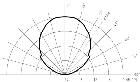
The sensor is capable of a fast sample rate of up to 50 samples per second ( i.e 20 ms update interval), fast enough for real time tracking and dynamic object detection and has a symmetric directivity of ±35°, providing a wide field of view for object detection.
From an electrical standpoint, the module is designed for easy integration, requiring only a single power supply ranging from 8 V to 18 V (typically 12 V) to drive all its internal electronics. The current consumption is a nominal 5.5 mA, making it suitable for power conscious applications.
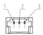
Interfacing is handled via a simple 3 pin connector (present at the rear of the sensor) which provides power (1. VSUP), ground (2. GND), and a single proprietary bidirectional IO line(3. IO) for all digital communication between the sensor and a host.
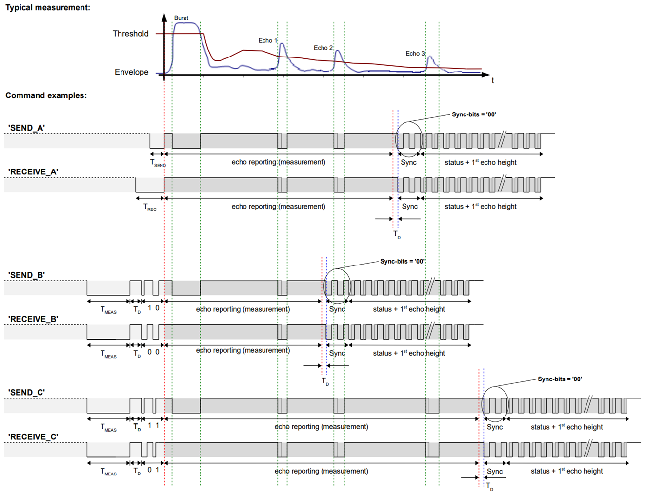
The standout feature here is the single wire IO interface. Rather than separate trigger and echo pins or a complex serial protocol, employs a proprietary PWM based communication scheme where the duration of low pulses encodes logical '0's and '1's. This bidirectional protocol supports a comprehensive command set, allowing deep customization of sensor behavior: detection thresholds, sampling modes, filtering parameters, and more, all negotiated over a single wire.
While this proprietary protocol means you can't simply drop the sensor into an Arduino sketch without additional library support, it's a clever trade off that minimizes pin count and simplifies routing in complex systems.
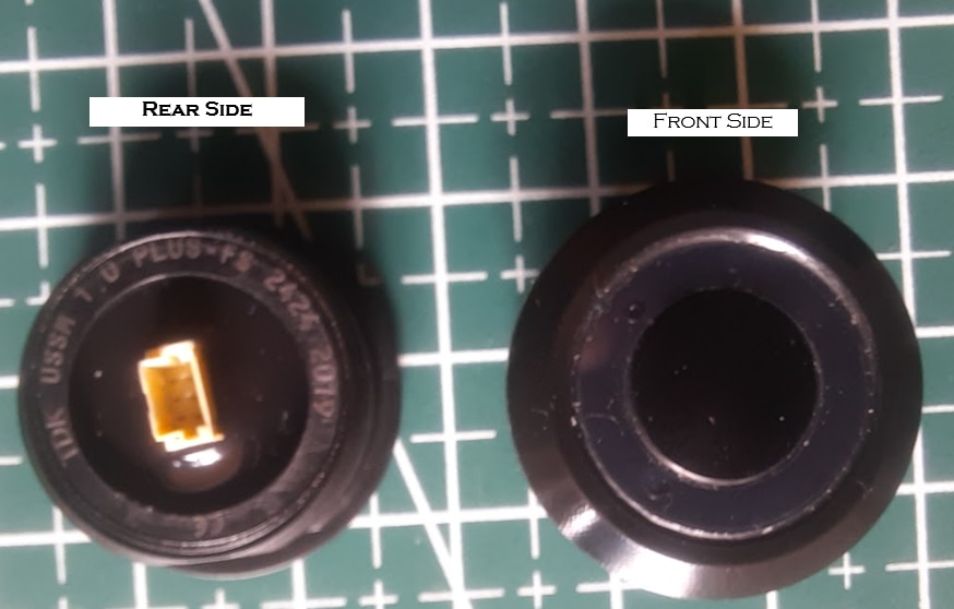
The E524.33 ASIC and supporting circuitry are potted in black epoxy resin, leaving only the 3-pin connector exposed. This encapsulation provides excellent moisture resistance, chemical protection, and mechanical durability which is critical for the outdoor, harsh environment applications the sensor is marketed toward.
Upon closer inspection, the professional finish of the sensor extends to its clear and comprehensive labeling. Each sensor is permanently marked with key information, which is essential for traceability and identification in a development or production environment.
These markings include:
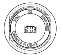
- TDK: Manufacturer
- USSM1.0 PLUS-FS: Product and variant identification code.
- YYCW XXXX: A unique serial number which also encodes the year and week of production.
- CE mark: Indicates conformity with health, safety, and environmental protection standards for products sold within the European Economic Area (EEA).
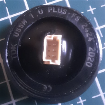
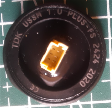
My two sensors carry serial numbers 2019 and 2020, both manufactured in calendar week 24 of 2024 (2424 marking). This level of traceability is uncommon in maker space components but essential for quality control, warranty claims, and compliance documentation in commercial deployments.
Sensor Connection Cables
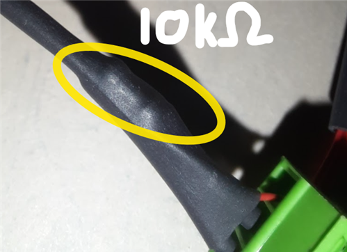
While often overlooked, the quality of the interconnects is critical for a reliable system. The kit includes two dedicated sensor connection cables that serve as the vital link between the TDK USSM1.0 PLUS FS sensors and the USSM Demo Board. The build quality of the cables is excellent. The wiring is appropriately gauged for delivering power and carrying the high-speed data signals without degradation. The length of the cables is generous, providing ample flexibility for bench top prototyping and for positioning the sensors at a reasonable distance from the evaluation board.
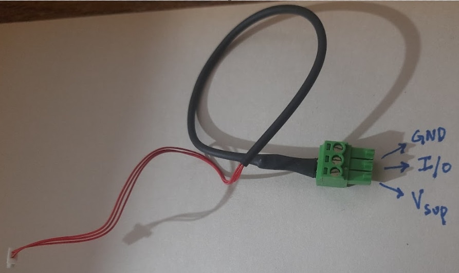
Each cable is terminated with two distinct connectors:
- Sensor End: A compact, white 3 pin female connector designed to mate perfectly with the integrated socket on the rear of the USSM sensor.
- Board End: A slightly larger, green 3 pin female 3.5mm pluggable screw terminal that plugs directly into the corresponding male headers on the TDK evaluation board.
Note : There's a 10K Ohms pull-up resistor hidden within the cable between the Vsup and the IO pins.
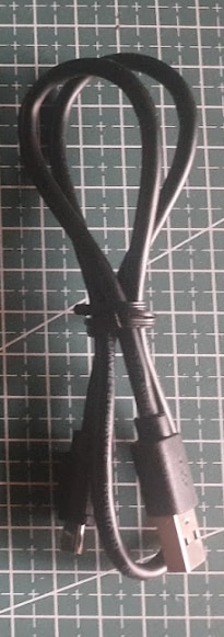
Micro USB B to USB A Cable
A stable and reliable connection to the host computer is fundamental for development. The kit includes a high-quality Micro B to USB A cable that serves this dual purpose, providing both power to the entire evaluation board and the data channel for programming and monitoring.
Upon inspection, the cable sheath is marked with its full technical specification: "USB SHIELDED HIGH SPEED CABLE 2.0 REVISION 28AWG/1P + 28AWG/2C". This string is not just for identification; it is a concise summary of the cable's construction and certifies its performance capabilities.
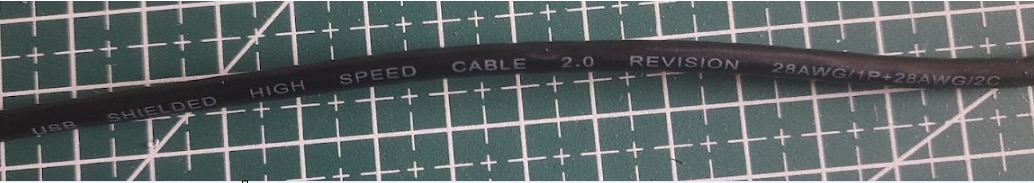
Let's dissect this specification
- USB HIGH SPEED CABLE 2.0 REVISION: This confirms the cable is fully compliant with the USB 2.0 standard, designed to support "High Speed" data rates of up to 480 Mbit/s. This ensures fast and efficient communication for programming the board and for real-time data streaming from the sensor without bottlenecks.
- SHIELDED: This is a critical feature for ensuring signal integrity. The internal wires are wrapped in a metallic shield (a foil or braid) that protects the data and power lines from external electromagnetic interference (EMI). In a project environment that will include motors and other sources of electrical noise, this shielding is essential for preventing data corruption and ensuring stable operation.
- 28AWG/1P (1 Pair): This indicates the cable contains one twisted pair of 28AWG (American Wire Gauge) wires. The USB 2.0 standard requires the data lines (D+ and D-) to be twisted together. This design cancels out crosstalk and external noise, which is fundamental for maintaining error-free, high-speed data transmission.
- + 28AWG/2C (2 Conductors): This refers to the two additional single conductors of 28AWG wire within the cable. These are dedicated to power delivery: one for the +5V supply and one for Ground (GND). The 28AWG thickness is standard and appropriately sized to deliver the necessary current to power the USSM Demo Board and its connected sensors.
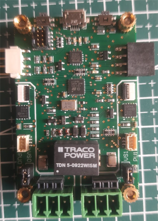
TDK USSM Sensor Demo Board
The TDK USSM Demo Board is a comprehensive development and evaluation platform engineered specifically for the USSM series of ultrasonic sensors. It serves as a hardware abstraction layer, providing the necessary power, communication, and processing capabilities to interface the sensors with a host PC.
Top Side View
Bottom Side View
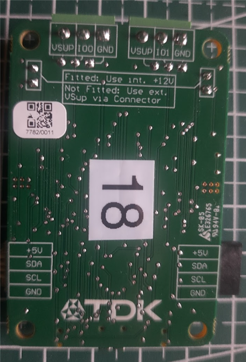
The first impression of the board is one of high-quality manufacturing. The 2 layer PCB construction feels robust and well manufactured, with a clean layout that suggests thoughtful design consideration. Component placement follows a logical hierarchy, avoiding the cramped, chaotic arrangement often seen in budget development boards. The soldering quality is exceptional with clean joints, consistent fillet formation, and no cold solder bridges or flux residue, indicating precision manufacturing processes.
However, the board isn't without its usability quirks. The most glaring omission is the lack of silkscreen labeling for key components. While this minimalist aesthetic might appeal to experienced developers, it creates an unnecessary barrier for newcomers. The buttons, in particular, present a guessing game; without clear markings indicating which is BOOT and which is RESET needing to reference the documentation. This becomes especially frustrating during rapid prototyping when quick resets are needed.
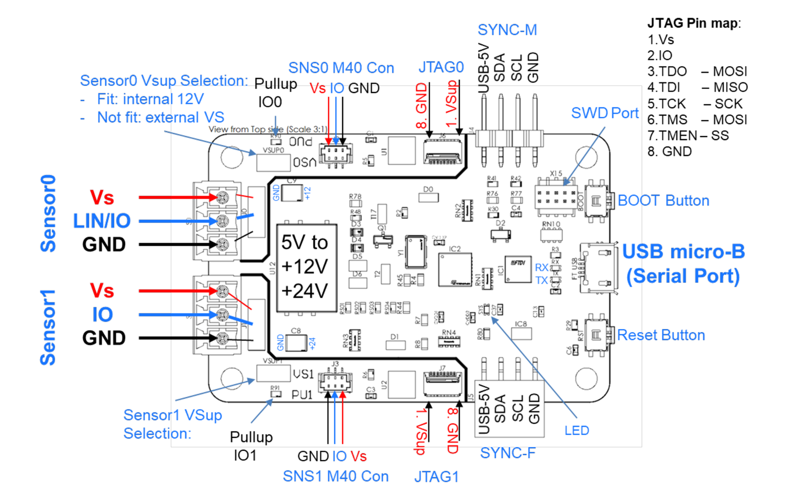
Here's the image labeling the connectors on the board as provided in the documentation :
Now let's look into other functional IC's on board,

The board is populated with an STM32L432KBU6 MCU, a high-performance, ultra low power microcontroller from ST Microelectronics based on the Arm Cortex M4 core, equipped with an FPU and DSP instructions for efficient data processing. The firmware leverages its on chip peripherals, including Timers (in Input Capture mode for precise signal decoding), UART (for communication between the sensors through LIN Transceivers), and GPIOs.
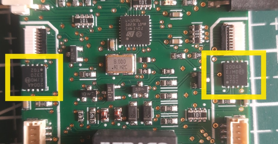
A critical component of the demo board's robust design is the use of a Microchip MCP2004A LIN transceiver for each sensor port. While the USSM sensor communicates via a proprietary single wire protocol, the MCP2004A is employed as an exceptionally effective and hardened physical layer to bridge this protocol with the MCU's logic-level I/O UART.
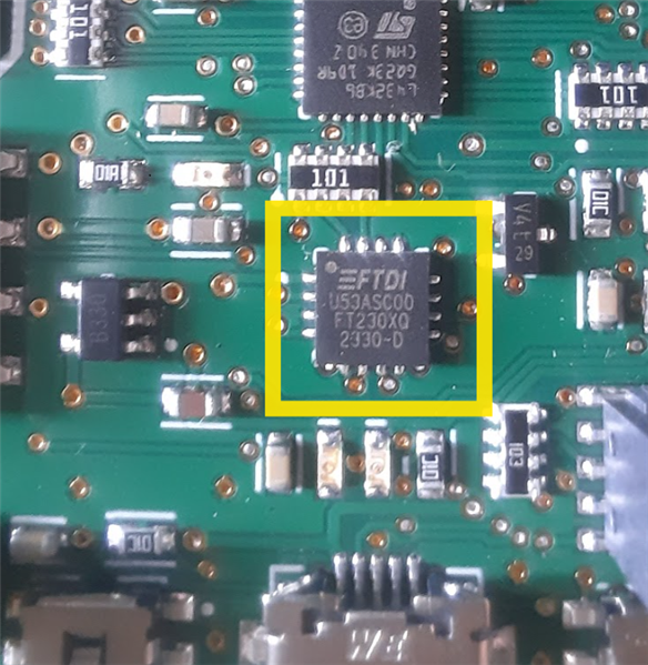
Host communication is managed by a dedicated FTDI FT230XQ USB to UART bridge IC, ensuring maximum driver stability and compatibility by presenting a standard virtual COM port to the host PC.
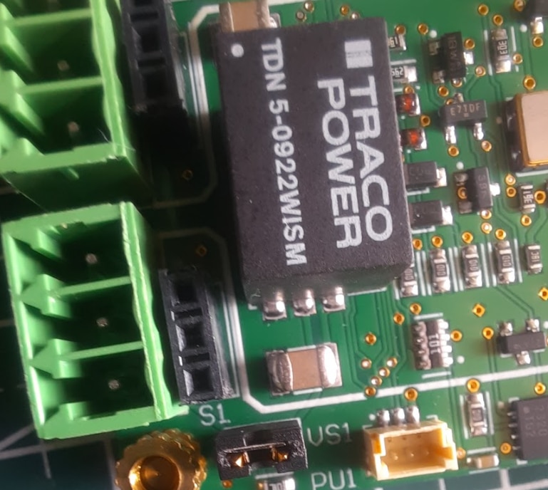
The board's power architecture is fully self contained, deriving all power from the 5V USB VBUS. The generation of the higher voltages required by the sensors and their interface circuitry is handled by a single, highly integrated component: a TRACO POWER TDN 5-0922WISM DC-DC converter module. The selection of a complete module rather than a discrete controller IC is a significant design choice that prioritizes reliability, noise immunity, and simplification of the board layout.
A key specification of this component is its I/O isolation, rated at 1.6 kVDC, which electrically separates the input ground (tied to the host PC) from the output ground used by the sensor circuitry. This isolation is critical for preventing ground loops and protecting the host system from potential electrical faults or transients on the sensor side.
The module is designed for a nominal 5V input, making it perfectly suited for direct operation from the USB VBUS. A defining feature is its dual output capability; it simultaneously generates two independent, regulated voltages from the single input.
The primary +12V rail serves as the operational supply (VSUP) for the USSM sensors and provides the necessary voltage for the MCP2004A LIN transceivers.
The secondary +24V rail is dedicated to a specific, high-voltage function: the programming of the sensor's internal EEPROM.
Furthermore, the module incorporates a Remote On/Off pin, which is connected directly to a GPIO of the STM32 microcontroller. This provides the firmware with programmatic control to enable or disable the entire high voltage power stage, allowing for advanced power management or, more critically, the ability to perform a hard power-cycle reset of the sensors by toggling their VSUP supply.

The board also includes standard SWD (Serial Wire Debug) access for in circuit programming and debugging, along with RESET and BOOT buttons for manual MCU control during firmware development.
Mounting the USSM's in the Enclosure for Testing
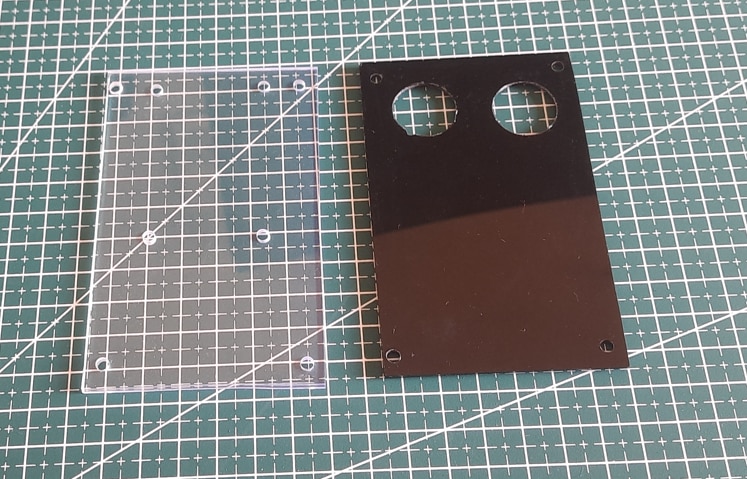
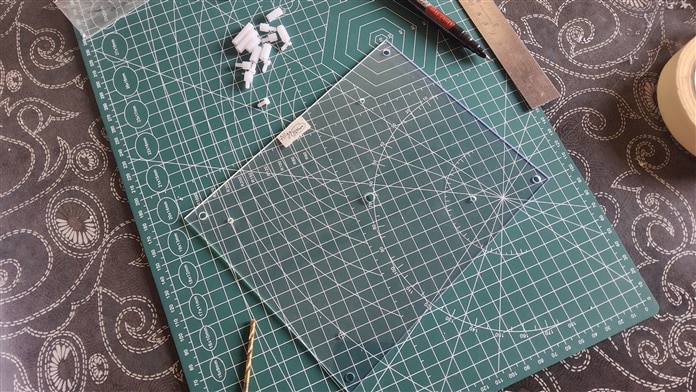
Before even plugging anything in, I wanted to give my hardware a proper enclosure. A stable and secure mounting for the USSMs is critical for getting clean, repeatable data. So, I designed a simple but effective case using two acrylic sheets as shown in the below, the transparent sheet(on the left) to mount the demo board which is the bottom layer and the black opaque sheet (on the right) which is the top layer having mounting holes for the USSM sensor.
The USSMs are mounted as per the instructions(as shown below) which is given in the sensor's datasheet.
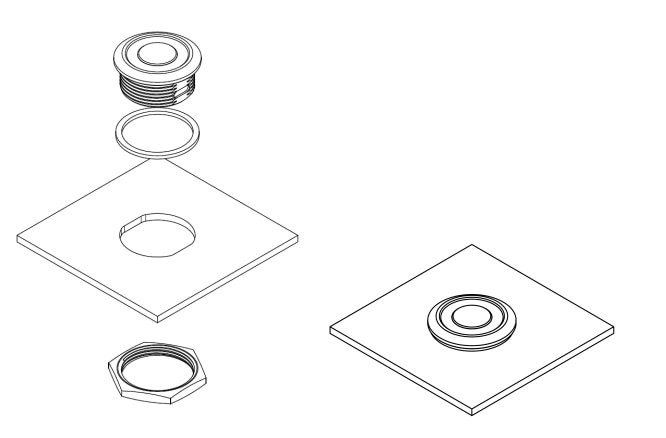
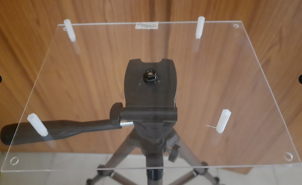
This acrylic enclosure allows the two USSM1.0 PLUS-FS sensors to be snugly fitted and secured with their included locking nuts. This setup not only protects the two USSM's but also provides a solid base for the demo board along with the USSM's, so that I can easily mount them to a tripod for testing and configuration.

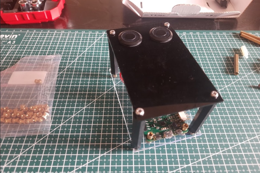
Here's how it looks after all the assembly is done.
Getting the TDK USSM GUI
Now that I have fitted the sensors and the demo kit into the enclosure, I can proceed to download the GUI by going to the TDK Demo Kit Software downloads page.
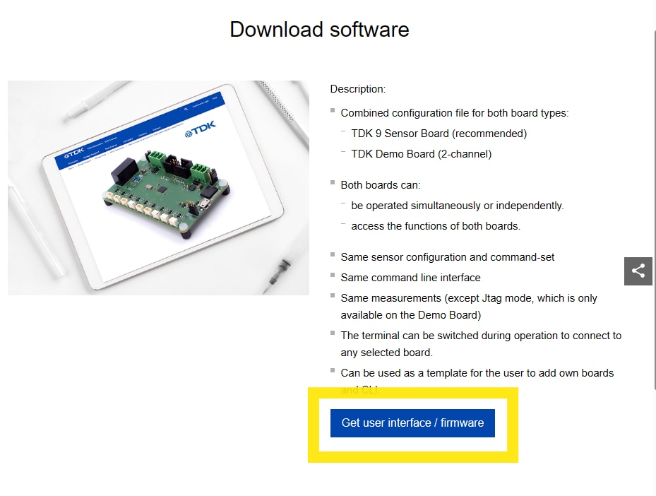
And then I clicked on get user interface/ firmware.
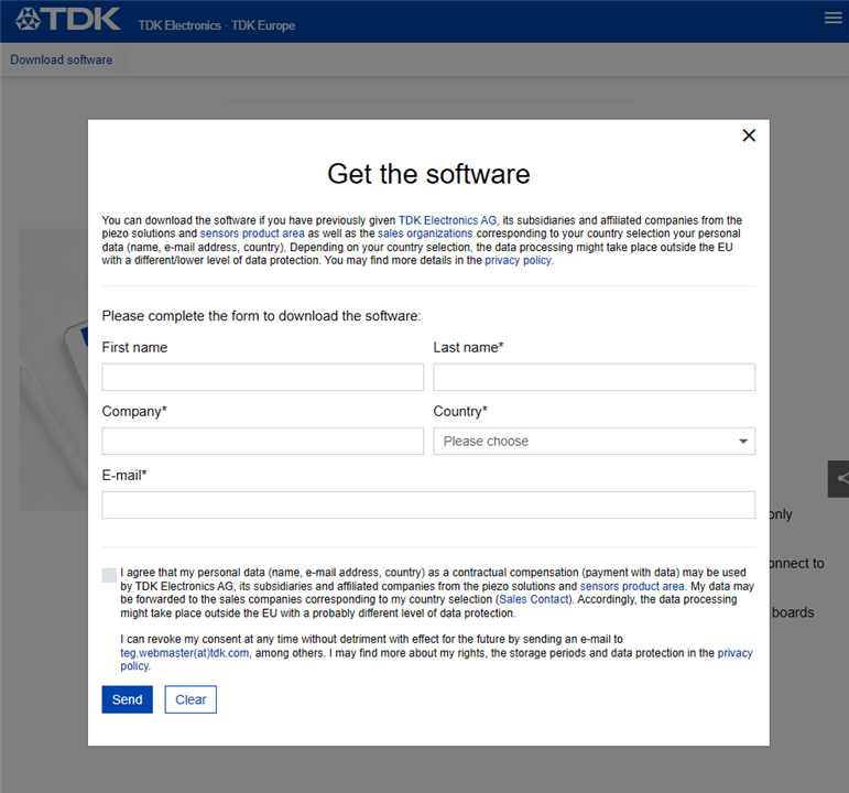
Then I entered the details in the pop-up “Get the Software” then clicked on send and got the download option(as shown below) to download the .zip file.
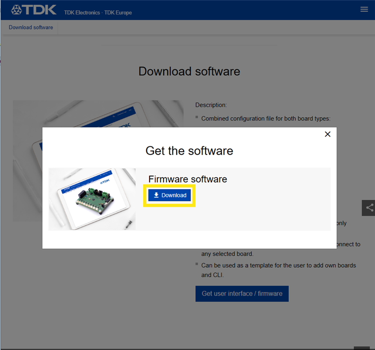
After the .zip file is downloaded I extracted the files to a folder. There's a folder named "config" and an .exe file. The .exe file named "20250228_TDK_USSM_Sensor_GUI_V3.5" is the GUI for the USSM Demo kit.
Note : The instructions for installation and using the GUI, provided in the reference manual seems to be for the previous version of the GUI which is different as compared to the present(v3.5) version of the GUI available for download.
Exploring the TDK USSM Demo Kit's GUI
Now, after downloading and extracting the GUI, I connected the demo kit to the PC via the USB cable and then launched the GUI.

Note: The demo kit has to be connected to the PC before launching the GUI, else the GUI doesn't detect the connected demo kit and you'll have to relaunch the GUI for it to detect the demo kit.
After the GUI loaded I was greeted with the home screen consisting of the Measurements, Data Visualization and the Terminal sections as shown below.
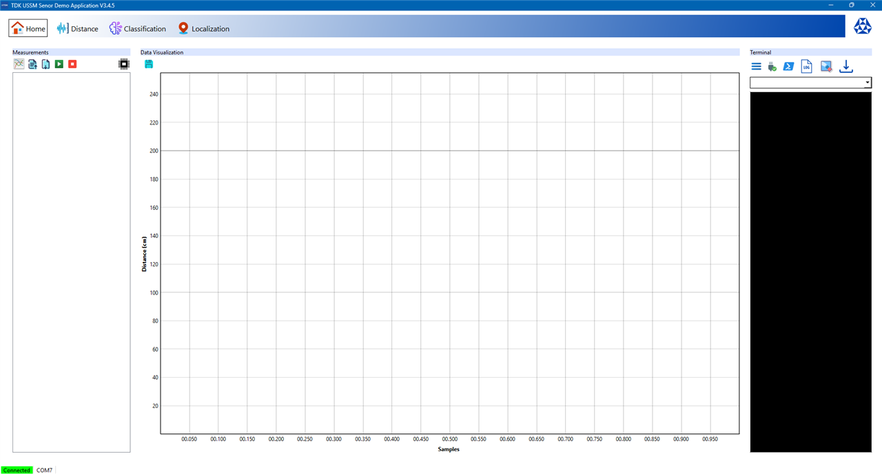
At the bottom of the GUI application the connection status and through which COM port the device is connected is listed.
Measurements Section
The measurements section is the command panel for running tests. It's possible to add new measurement tasks, select from the sensor's various operational modes as shown below.
| CAL_PULSE | Calibrates the sensor's internal oscillator. It ensures the timing for measurements is correct. |
| SEND_A, SEND_B, SEND_C | In this mode, the sensor sends an ultrasonic pulse and measures how long it takes for the echo to return from an object. SEND_A is the usual mode for simple trigger-and-echo operations. The A, B, and C variants match three different measurement profiles that can be configured and stored on the sensor. |
| RECEIVE_A, RECEIVE_B, RECEIVE_C | The sensor does not send its own pulse but listens for incoming ultrasonic signals using one of the three measurement profiles. These modes are helpful for pitch-catch applications, where one sensor sends and another receives. |
| SEND_RECEIVE_A, SEND_RECEIVE_B, SEND_RECEIVE_C | These mode lets the user to set a specific "master" sensor(s) to send a pulse while other sensors listen at the same time. This can be used for triangulating the location of objects in a 2D space. |
| ENV_SEND_A | Delivers the raw analog envelope signal. Rather than just giving a calculated distance, the sensor sends a pulse and outputs the full shape of the received echo signal over the IO line. This is useful for in-depth analysis or evaluation. |
| ENV_RECEIVE_A | This is similar to ENV_SEND_A, but it operates in "listening only" mode. The sensor outputs the raw analog envelope of any ultrasonic sound it detects without sending a pulse first. |
| ENV_SEND_RECEIVE | This is a multi sensor diagnostic mode that combines sending and receiving the raw analog envelope signal. |
| STREAMOUT | This mode allows for live-streaming distance measurements in centimeters. When activated, the enabled sensors continuously perform a SEND_A measurement and report the distance until the end command is issued. |
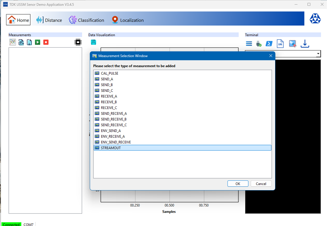
"STREAMOUT" is the preferrable type of measurement for my initial testing which involves getting the sensor's reading in centimeters so as to check how accurate the distance reading from the USSM is. Another point to be noted is that only one type of measurement can be active at a time, it's not possible to allocate multiple type of measurements for each USSM.
The measurements section can also be used to assign specific sensors to the measurement task, and then start, stop, and save or either export the results from/to a file. There's also a icon to access the Registers Window which allows for the configuration of the sensors parameters.
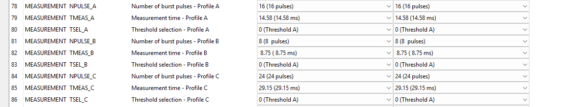
Note: The measurement profiles A,B,C can also be configured through this Registers Window.
Data Visualization Section
It's a real time graphing window that visualizes the data from the USSMs. It's possible add and visualize data from multiple USSMs and see the sensor's perception through this section.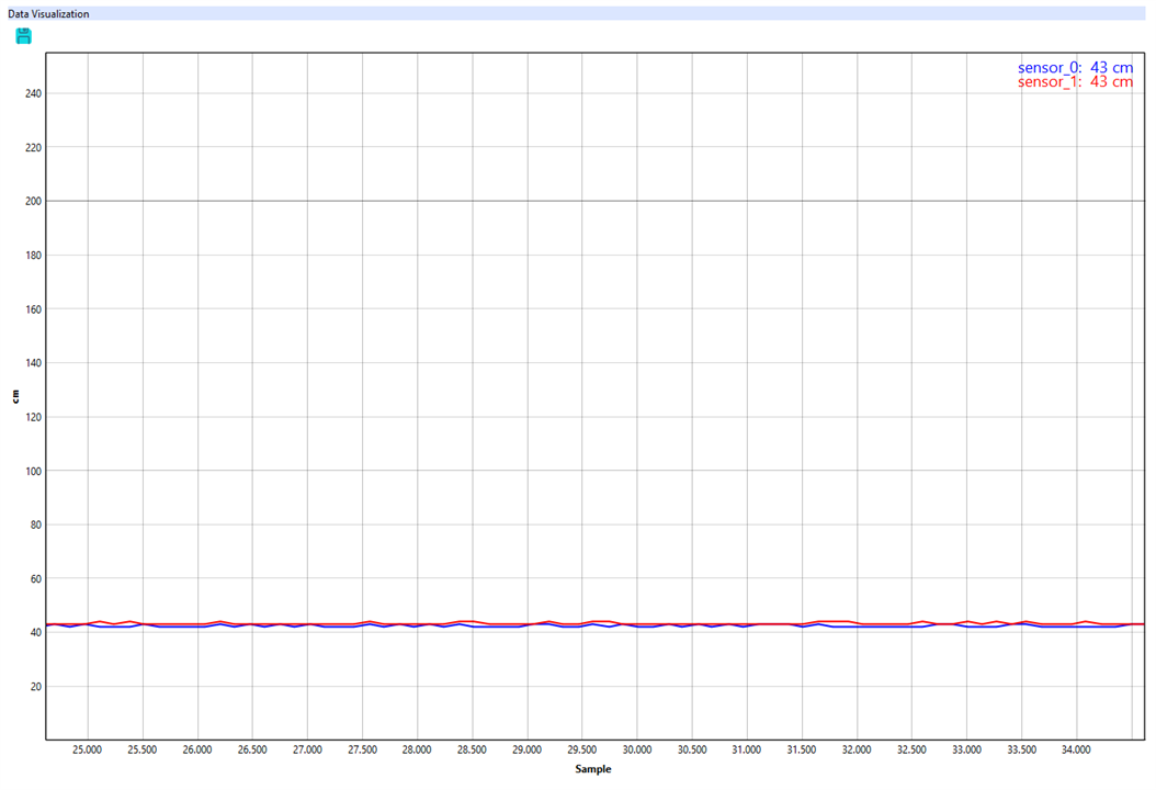
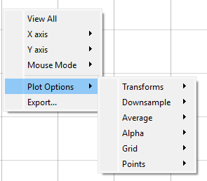
Note : It also has some features for data analysis through transforms, accessible by right-clicking on the graph, which is useful for some quick analysis of the USSM's waveforms.
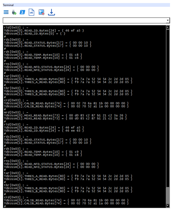
Terminal Section
This is the only working serial console available to pass send commands(as listed in the reference manual) directly to the demo kit through the COM port. It's also possible to save the log of commands and update the firmware of the board in this terminal section.
Measurements and Registers Configuration
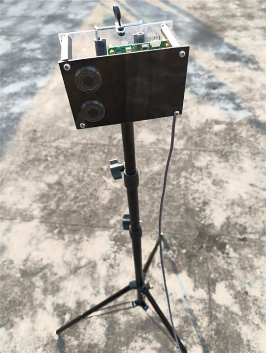
I mounted the TDK USSM Demo Kit on the tripod stand and took it outside to take some measurements using the solo mode for each USSM, by placing a wooden surface nearly 3 feet away from the sensors.
Here's how it looks
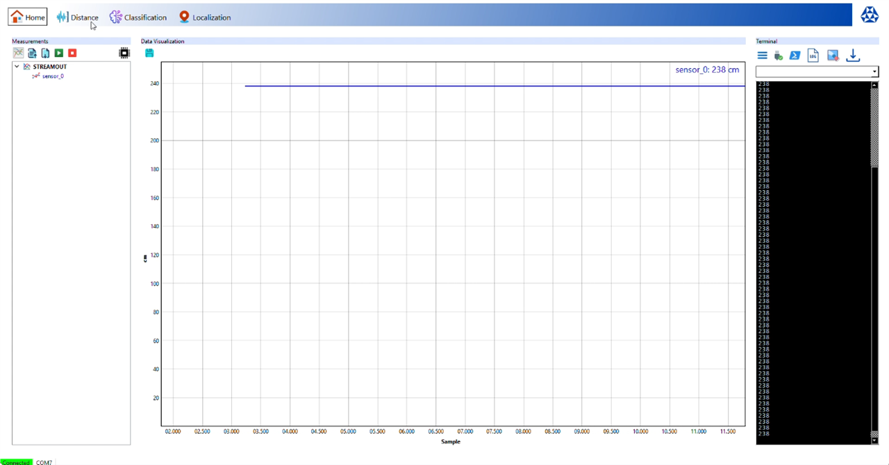
Now, using the "STREAMOUT" measurement type, I observed the measurements from the USSMs.
It seems like the sensor_0 was giving me some fluctuating and "jumpy" readings, especially when compared to the sensor_1's readings, the same result can also be observed from the Distance tab (only the solo measurement mode is available to test even though the picture at the center of GUI shows the range for pitch and catch mode) in the TDK GUI.
Even after placing the the sensors nearly 2 feet away from the wooden surface the sensor_0 readings had too much of the fluctuations.
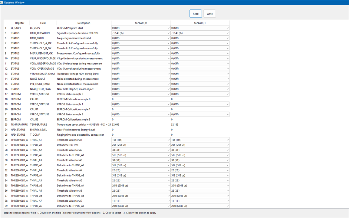
So, I looked into the sensor parameter's through the Registers Window and found that the some of the register values were a bit different.
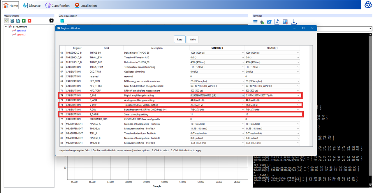
My first thought was that this might be an error. But in fact, this is probably the sign of calibration during the manufacturing process. No two physical components are ever perfectly identical. There may be some tiny, microscopic variations in the piezoelectric material of the transducer or in the analog components of the ASIC and TDK probably performed an end of line calibration for each sensor, testing its specific performance and then writing a unique set of calibration values to its internal EEPROM (non volatile memory) to compensate for the these defects.
This discovery also likely explains an issue I was having, was related to these parameters. So I did adjust the noise suppression from 0% to 50% and the temperature, to try and see if the readings are stabilized for the sensor_0.
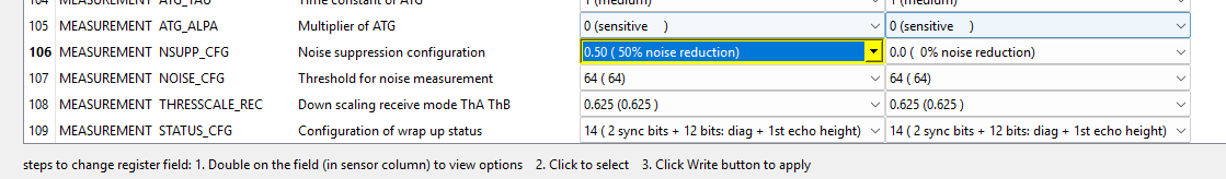
After comparing the data from the STREAMOUT measurement for both the USSM's the readings seems to be relatively stable after the calibration, with the margin of error within +/- 1cm.
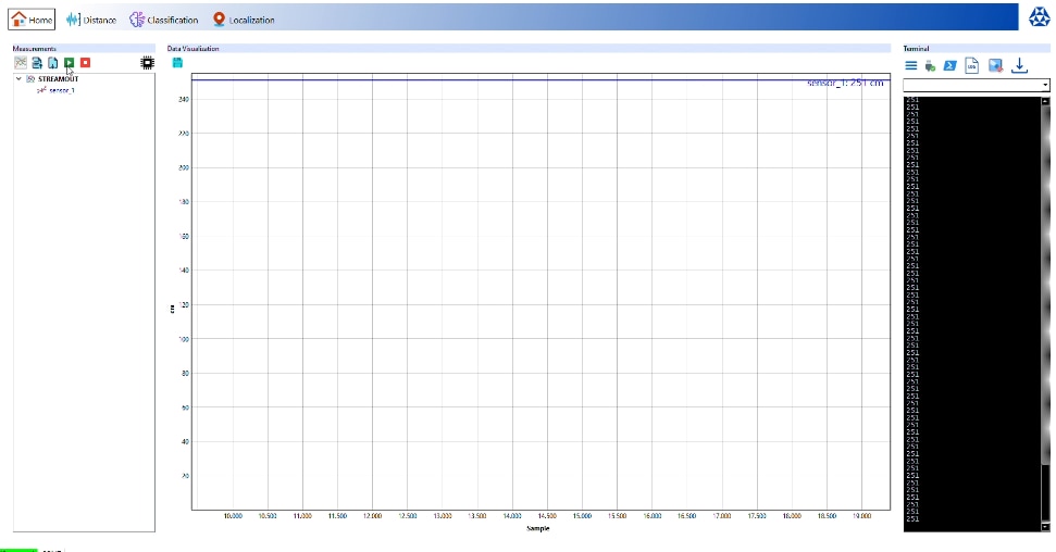
Then, I moved the the wooden surface and then did a max range test of the USSM's solo mode (only the pitch and catch mode has the max range of 5m) both the sensors gave different values.
Sensor_0 maxed out at 238 cms
Sensor_1 maxed out at 251 cms.
Here's my final register configurations
set[0x01] FILTER_CFG 1 ; →
TdkUssm[0].MEAS_READ.Bytes[73] = { 00 d0 85 c2 87 b1 21 c2 3a 26 }
TdkUssm[0].MEASUREMENT.FILTER_CFG = 1
TdkUssm[0].MEAS_WRITE.Bytes[73] = { 00 d0 85 c2 97 b1 21 c2 3a 26 }
#
set[0x02] FILTER_CFG 1 ; →
TdkUssm[1].MEAS_READ.Bytes[73] = { 00 d0 85 c2 87 b1 21 c2 3a 26 }
TdkUssm[1].MEASUREMENT.FILTER_CFG = 1
TdkUssm[1].MEAS_WRITE.Bytes[73] = { 00 d0 85 c2 97 b1 21 c2 3a 26 }
#
set[0x01] NSUPP_CFG 1 ; →
TdkUssm[0].MEAS_READ.Bytes[73] = { 00 d0 85 c2 97 b1 21 c2 3a 26 }
TdkUssm[0].MEASUREMENT.NSUPP_CFG = 1
TdkUssm[0].MEAS_WRITE.Bytes[73] = { 00 d0 85 c2 97 b1 21 c2 3a 66 }
#
set[0x02] NSUPP_CFG 1 ; →
TdkUssm[1].MEAS_READ.Bytes[73] = { 00 d0 85 c2 97 b1 21 c2 3a 26 }
TdkUssm[1].MEASUREMENT.NSUPP_CFG = 1
TdkUssm[1].MEAS_WRITE.Bytes[73] = { 00 d0 85 c2 97 b1 21 c2 3a 66 }
#
set[0x01] FILTER_CFG 0 ; →
TdkUssm[0].MEAS_READ.Bytes[73] = { 00 d0 85 c2 97 b1 21 c2 3a 66 }
TdkUssm[0].MEASUREMENT.FILTER_CFG = 0
TdkUssm[0].MEAS_WRITE.Bytes[73] = { 00 d0 85 c2 87 b1 21 c2 3a 66 }
#
set[0x02] FILTER_CFG 0 ; →
TdkUssm[1].MEAS_READ.Bytes[73] = { 00 d0 85 c2 97 b1 21 c2 3a 66 }
TdkUssm[1].MEASUREMENT.FILTER_CFG = 0
TdkUssm[1].MEAS_WRITE.Bytes[73] = { 00 d0 85 c2 87 b1 21 c2 3a 66 }
#
set[0x01] NEAR_FIELD_FLAG 1 ; →
TdkUssm[0].READ_STATUS.Bytes[17] = { 00 01 10 }
TdkUssm[0].STATUS.NEAR_FIELD_FLAG = 1
TdkUssm[0].NOP.Bytes[0] = { }
#
set[0x02] NEAR_FIELD_FLAG 1 ; →
TdkUssm[1].READ_STATUS.Bytes[17] = { 00 01 10 }
TdkUssm[1].STATUS.NEAR_FIELD_FLAG = 1
TdkUssm[1].NOP.Bytes[0] = { }
#
Hardware Setup
Required Hardware
| TDK USSM Demo Kit | Ultrasonic sensing module for precise distance measurement and object proximity detection. |
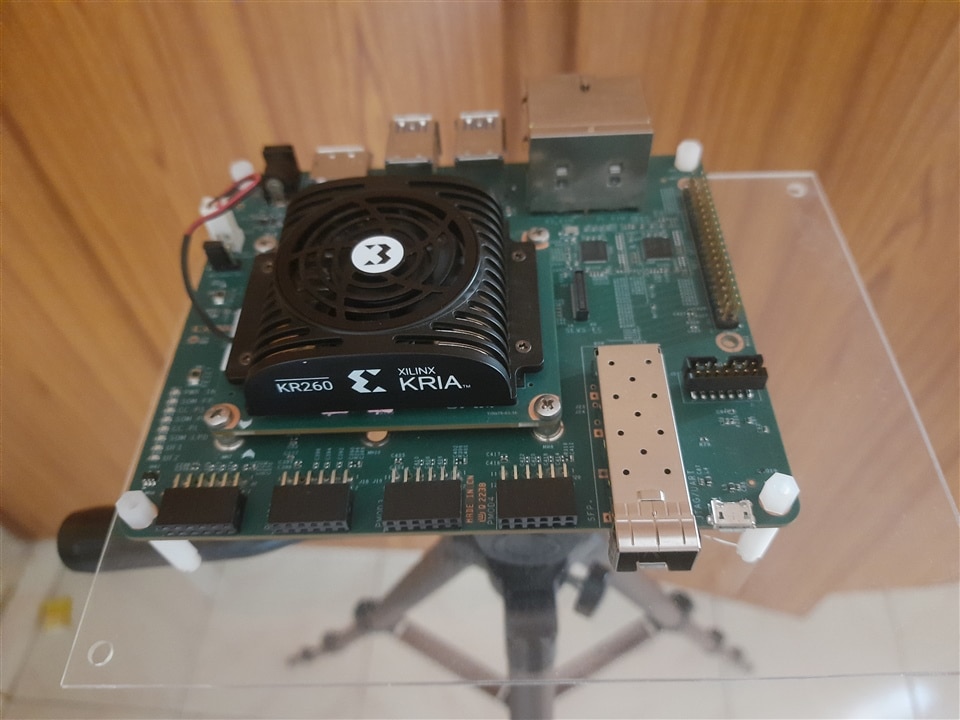
| KR260 Robotics Starter Kit | Primary computing platform featuring AMD Xilinx Kria K26 SoM for real time ML inference, sensor data processing, and ROS2 middleware integration. |
| Wireless USB Adapter | Enables WiFi connectivity for remote monitoring, data transmission, and network based control. |
| USB Camera Module | Captures real-time video for vision processing, object detection, and environmental perception. |
| Mounting Spacers | Hardware fasteners for secure component installation and proper PCB elevation. |
| Adjustable Tripod Stand | Provides stable support with adjustable height and positioning for optimal sensor placement. |
| Acrylic Mounting Sheets | Rigid, transparent platform for organized hardware assembly and improved cable management. |
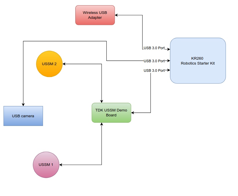
Block Diagram
Here's the block diagram showing how the hardware is connected to the KR260
Setting up...
The setup starts with preparing the acrylic sheets, cutting them to the required size for the tripod mounting and drilling the mounting holes to mount the hardware.
The main support structure has a two-layer design with upper and lower platforms. An additional medium-sized sheet is used for mounting the camera and TDK USSM modules. A smaller sheet is specifically reserved for the TDK Demo Kit.

Assembly begins with securely attaching the bottom acrylic layer to the tripod stand. This creates a stable foundation for the entire system.
Once the base is properly positioned and leveled, the KR260 Robotics Starter Kit is installed on this bottom layer with the help of plastic spacers. These spacers serve two purposes: they provide electrical isolation for the board and ensure there is enough space for ventilation, which helps with thermal management.
With the controller in place, the next step is to create the upper structure. Metal spacers establish standoffs between the bottom and top layers, ensuring both strong structural support and effective heat dissipation. The TDK Demo Kit is securely positioned on this top acrylic platform.
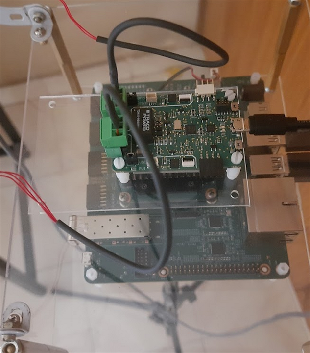
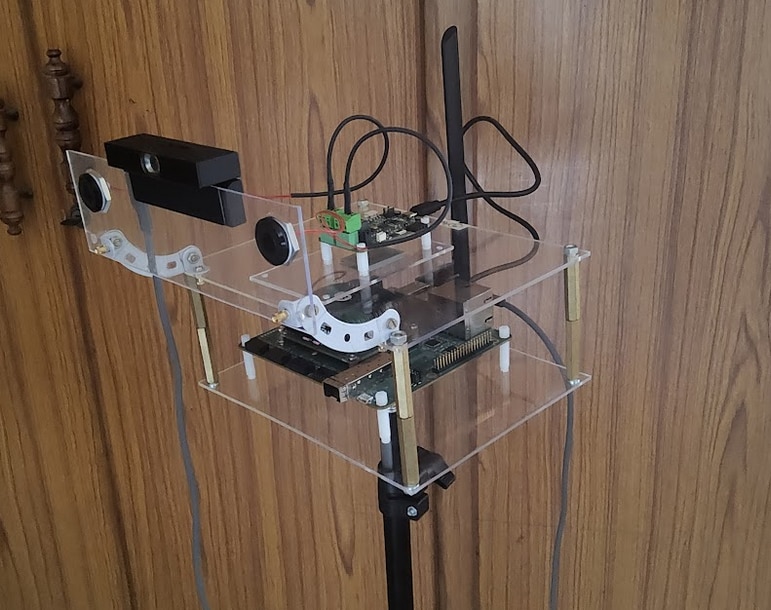
The final phase of setup focuses on installing the sensor module. The USB camera is attached to its designated mounting sheet using a magnetic mount that allows for quick adjustments and repositioning. The TDK USSM modules are installed next to the camera on the same sheet.This complete camera + USSM sensor unit is then secured to the main structure using metal angle brackets. These brackets allow for tilting and adjusting the sensor orientation to achieve the best field of view and detection range.
Here's the final setup after assembly....
Setting Up the KR260
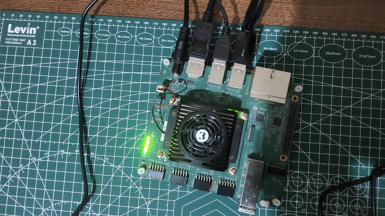
The KR260 was chosen for its FPGA accelerated AI processing and its built-in ROS2 support. This allows it to handle ML inference, camera feeds, and ultrasonic sensor data in real time. Its hardware acceleration and flexible I/O make it perfect for applications that use multiple sensors and need quick responses.
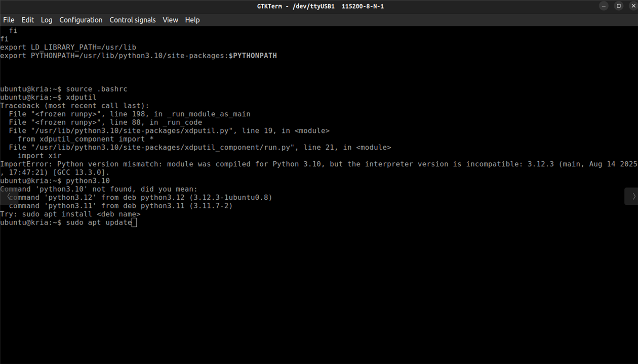
Ubuntu 22.04 on KR260
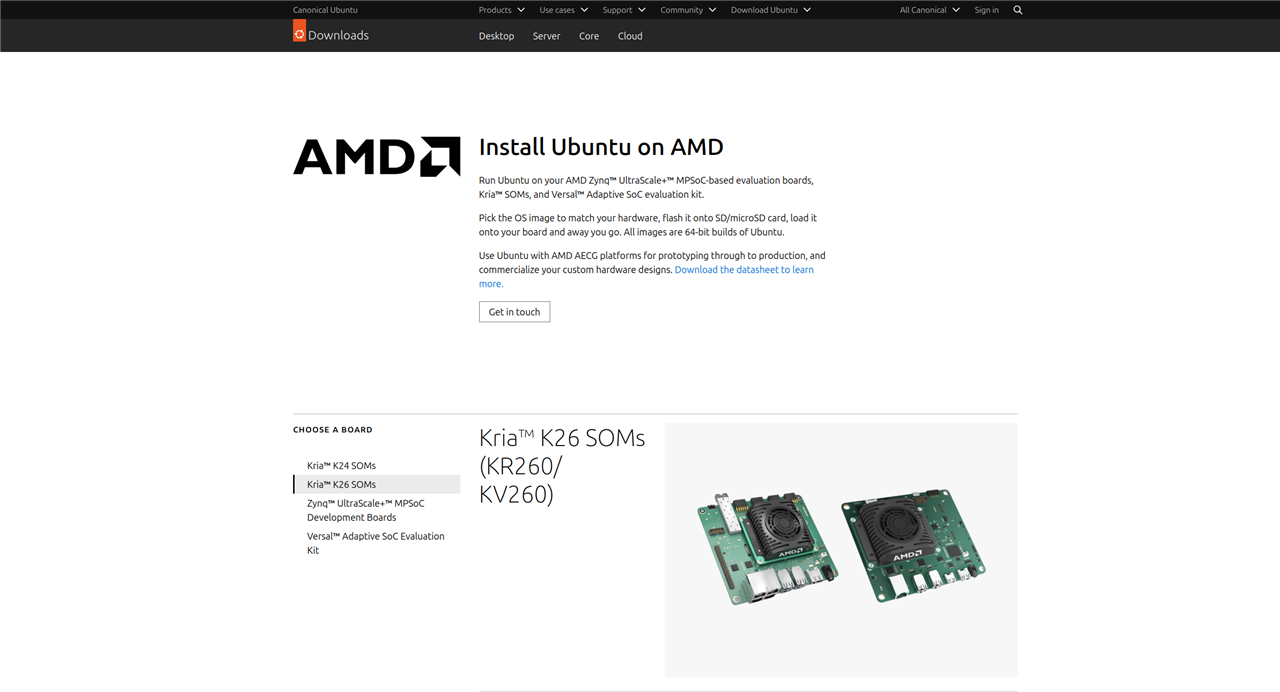
For this project I am using the Ubuntu 22.04 instead of the 24.04 version which is available as the latest version as I faced some issues due to the Python version mismatch during the startup when I set the default interpreter to python3.10 as the VART 3.5 requires it.
For the setup I referred the guide "Booting Kria Starter Kit Linux on KR260", which has all the information regarding the basic setup of the Ubuntu 22.04 for KR260.It's also better to choose an SD with a storage capacity of 64 GB max for flashing the Ubuntu 22.04.

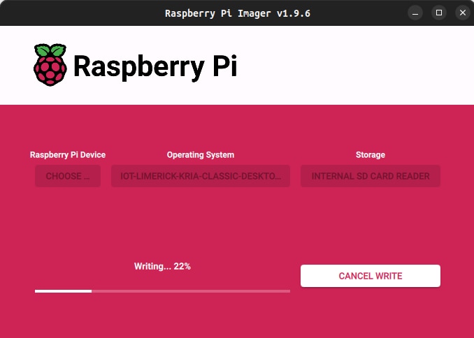
I used the Raspberry Pi Imager to flash the Ubuntu 22.04 Image onto the SD card.
Initialization
Before deploying AI workloads or running PYNQ overlays on the KR260, the board must be configured using AMD’s official initialization tools.This process prepares the operating system, sets up FPGA-related services, and installs board support packages to ensure that the runtime and PYNQ framework operate correctly.
The first step is to install the xlnx-config tool, which AMD provides through the Snap store. This utility automates KRIA-specific system configuration tasks, such as enabling FPGA management services, installing boot-time utilities, and preparing system directories used by XRT and runtime components. Installing the tool with the --classic option allows it to access the system-level paths needed for hardware configuration.
sudo snap install xlnx-config --classic --channel=2.x

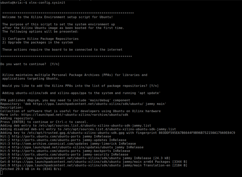
After installation, the board is initialized using the sysinit routine.
xlnx-config.sysinit
Setting Up PYNQ for Kria
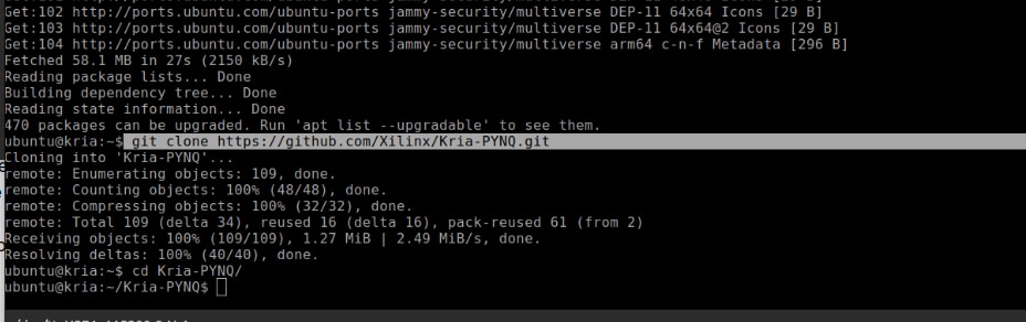
To enable a Python-based workflow on the KR260, AMD provides the Kria PYNQ framework. This repository includes board overlays, configuration scripts, Python drivers, and prevalidated examples.Cloning the repository ensures that the latest PYNQ board files and acceleration libraries are available locally for the setup.
git clone https://github.com/Xilinx/Kria-PYNQ.git
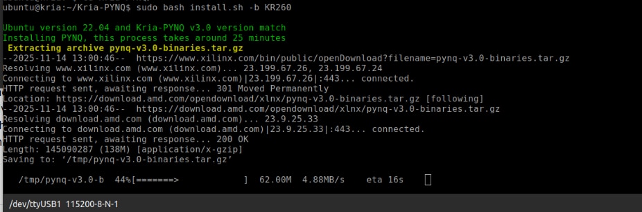
The final step is to run the installation script, specifying the target board. The install.sh script configures Jupyter, installs required Python packages, deploys PYNQ overlays, and sets up runtime services. Using the "-b KR260" flag ensures that the installation process applies the correct board-specific settings, including kernel modules and device-tree overlays.
sudo bash install.sh -b KR260
Setting up the Vitis AI 3.5 Runtime
Deploying AI workloads on the AMD/Xilinx KR260 requires the Vitis AI Runtime (VART). This runtime serves as the main execution engine for running quantized deep-learning models on the KR260’s DPU accelerator. The VART stack includes libraries for tensor processing, model graph handling, logging, and device abstraction. All of these need to be installed before running any inference workloads.
The Vitis AI runtime for KR260 is offered as a compressed ZIP file from AMD’s public download server. This package contains all the necessary libraries, device-specific binaries, and support tools.
wget -O vai3.5_kr260.zip "https://www.xilinx.com/bin/public/openDownload?filename=vai3.5_kr260.zip"
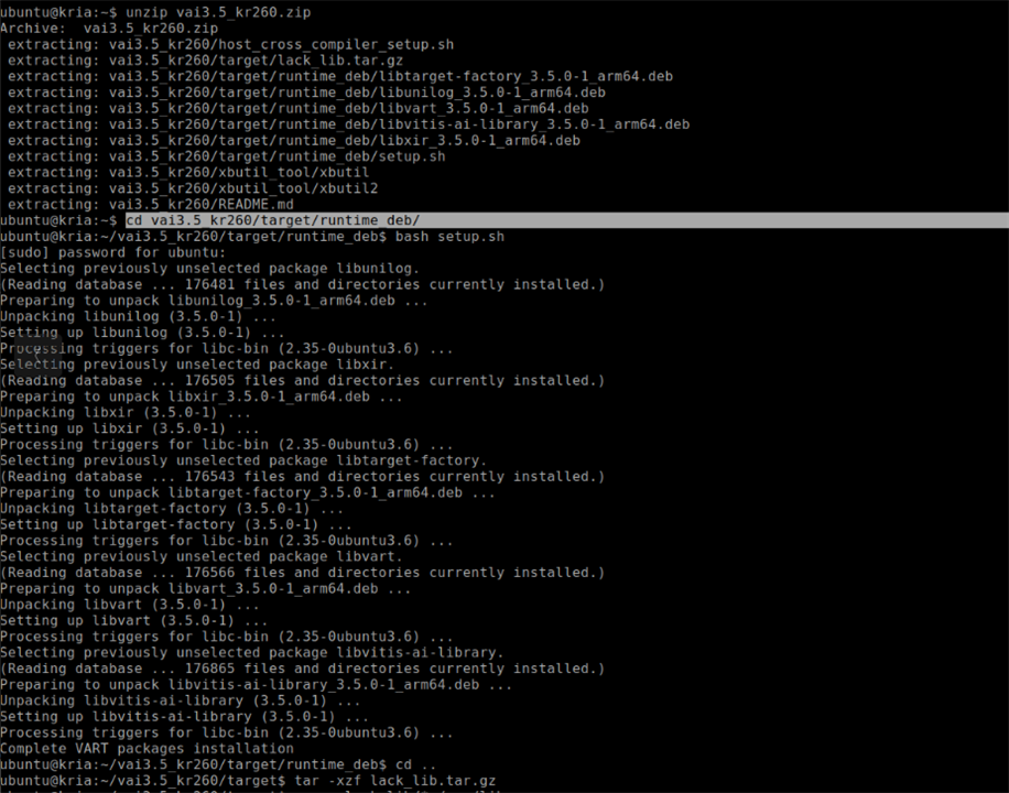
Once downloaded, the compressed archive must be extracted.
unzip vai3.5_kr260.zip
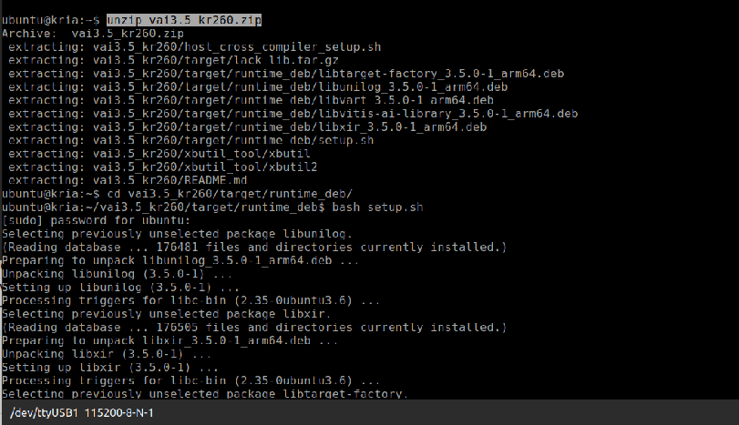
The runtime_deb directory holds Vitis AI's core runtime .deb files. These include important components like libunilog, libxir, libtarget-factory, libvart, and libvitis-ai-library. Together, they make up the VART execution layer. AMD provides a script called setup.sh in this directory to install these packages in the right order and ensure that earlier versions are upgraded properly.
pushd vai3.5_kr260/target/runtime_deb/
bash setup.sh
This script automatically installs all the needed dependencies and configures the system for Vitis AI inference.
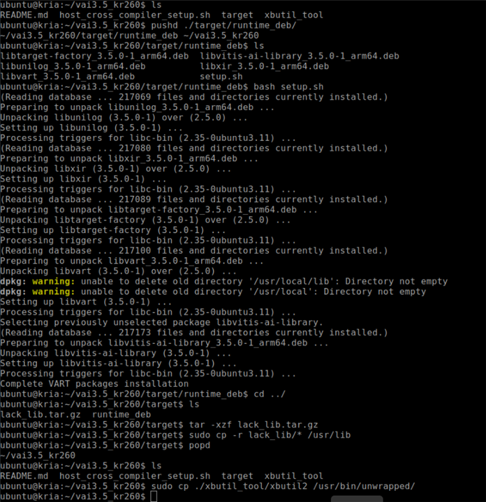
The KR260 Ubuntu image might lack certain low-level shared libraries needed by the Vitis AI runtime. AMD provides these in a compressed file named lack_lib.tar.gz. Extracting and copying them into /usr/lib fixes any missing dependency problems that could cause VART applications to fail at runtime due to unresolved symbols
cd ..
tar -xzf lack_lib.tar.gz
sudo cp -r lack_lib/* /usr/lib
After installing the runtime and any missing libraries, it’s helpful to return to the original working directory using the popd command. This step navigates back to the main vai3.5_kr260 folder, preparing for the installation of utilities like xbutil2.
popd
The KR260 needs a functioning xbutil2 utility for system inspection, FPGA health checks, and DPU diagnostics. This tool checks if the accelerator is properly initialized and if the Vitis AI runtime environment is ready for use. The utility is located in the xbutil_tool directory and must be copied to the correct system binary location (/usr/bin/unwrapped/) for the Ubuntu to recognize it.
sudo cp ./xbutil_tool/xbutil2 /usr/bin/unwrapped/
After installation, users can verify system health using
sudo xbutil2 examine
DPU-PYNQ Installation and Setup
To enable Vitis AI 3.5 acceleration on the Kria KR260 running Ubuntu with PYNQ, you need to install the DPU-PYNQ framework manually.
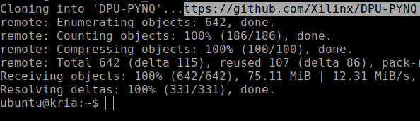
First, clone the official repository and switch to the branch for Vitis AI 3.5. This ensures compatibility with the updated DPU runtime, overlays, and metadata. After cloning the repository, navigate into the new directory to prepare for installation.
git clone https://github.com/Xilinx/DPU-PYNQ
cd DPU-PYNQ
Before installation can start, activate the PYNQ virtual environment (pynq-venv). This environment includes all required Python libraries like pynq, pynqmetadata, and pynqutils. Using the correct virtual environment is crucial since the system Python does not include these libraries. Activating the environment also ensures the installation targets the correct site-packages directory.
$ source /etc/profile.d/pynq_venv.sh
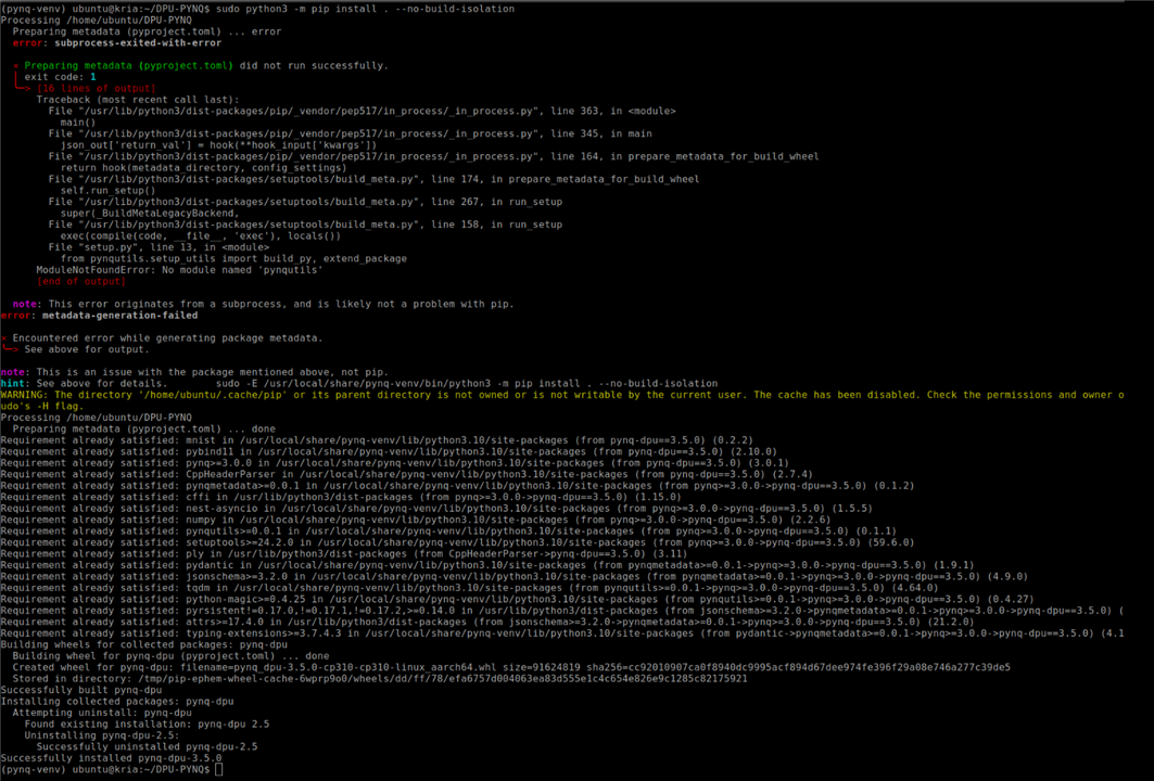
Once inside the venv, install the DPU-PYNQ package using the venv's Python binary, not the system Python.It's needed to use $ sudo -E to keep the environment variables active, allowing the venv to remain active even with elevated privileges. The flag --no-build-isolation ensures that the build uses the already installed PYNQ dependencies instead of creating temporary build environments.
sudo -E /usr/local/share/pynq-venv/bin/python3 -m pip install . --no-build-isolation
After installation, download all example notebooks included with the DPU-PYNQ package. These notebooks consist of inference tests, model runners, profiling tools, and Jupyter resources.
cd
pynq get-notebooks pynq-dpu -p . --force
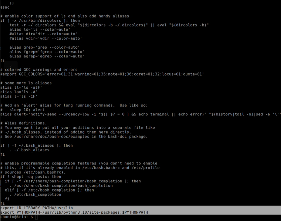
Next, apply an important system level fix. The Vitis AI runtime installs key shared libraries, such as libvart, libunilog, and libxir, in /usr/lib. However, the PYNQ virtual environment doesn’t look in /usr/lib by default. It's needed to extend the LD_LIBRARY_PATH in the venv activation script to make these libraries available during runtime using the below command
$ sudo sed -i -e '$aexport LD_LIBRARY_PATH=/usr/lib' /etc/profile.d/pynq_venv.sh
The xdputil tool, which inspects DPU configuration, model metadata, and performance statistics, hard codes a reference to /usr/bin/python. This makes it run outside the PYNQ virtual environment and breaks imports. To fix this, remove all absolute python path strings so it uses the currently active python i.e the venv python using the below command
$ sudo sed -i "s/\/usr\/bin\///g" /usr/bin/xdputil
Some Vitis AI Python bindings are installed in the global system path (/usr/lib/python3.10/site-packages). These modules include components needed by VART. To ensure the venv can import them correctly, extend the PYTHONPATH in the PYNQ environment activation script using the command
$ sudo sed -i -e '$aexport PYTHONPATH=/usr/lib/python3.10/site-packages:$PYTHONPATH' /etc/profile.d/pynq_venv.sh
Installing and Setting up ROS 2
To start setting up ROS 2 on the Kria KR260 board, first boot the system and open a terminal. Since ROS 2 must be installed within the PYNQ environment, switch to the root user and activate the PYNQ virtual environment by running
sudo su
followed by
Once in the environment, check the current locale settings by typing
locale
If UTF-8 is not already enabled, install the necessary locale support by running
apt update
apt install -y locales
After installation, generate the right UTF-8 locales with the command
locale-gen en_US en_US.UTF-8
Next, update the system's default locale settings with
update-locale LC_ALL=en_US.UTF-8 LANG=en_US.UTF-8
Ensure that UTF-8 is used in the current shell by exporting it with
export LANG=en_US.UTF-8
You can confirm that the locale has been correctly set up by running locale again and checking that LANG and related entries show en_US.UTF-8.
With the locale configured, the next step is to enable the necessary Ubuntu repositories. Start by installing the software-properties-common package using
apt install -y software-properties-common
which provides the tools needed to manage repositories.
After this, enable the Universe repository by executing
add-apt-repository universe -y
ensuring that ROS 2 packages and dependencies can be accessed properly. Some networks may have issues reaching GitHub’s raw content server, so to avoid download failures, append a static mapping to the /etc/hosts file by running the command
$ echo "185.199.108.133 raw.githubusercontent.com" >> /etc/hosts.
Then, update the system package index with apt update and install the curl utility with
apt install -y curl
You can now download and register the ROS 2 GPG key by running
curl -sSL https://raw.githubusercontent.com/ros/rosdistro/master/ros.key -o /usr/share/keyrings/ros-archive-keyring.gpg
Once the key is installed, add the official ROS 2 repository to the system's package sources. This is accomplished by executing the following command, which automatically detects the CPU architecture and Ubuntu release name:
With the repository set up, refresh the package index again by running
apt update
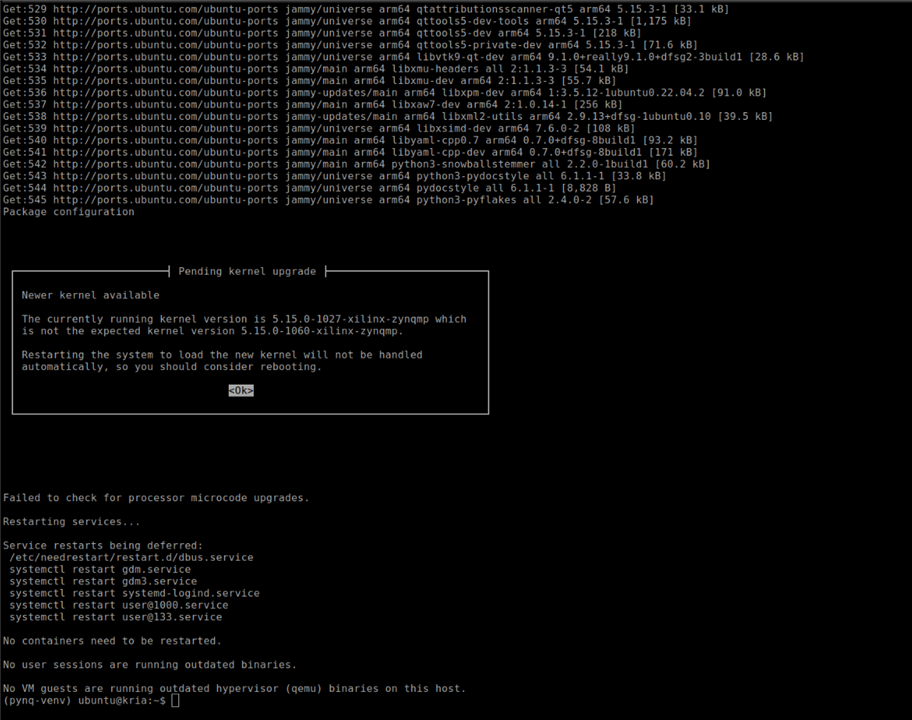
And then upgrade any outdated system packages by executing
apt upgrade -y.
You can now install ROS 2 Humble Desktop, the full distribution by running
apt install -y ros-humble-desktop
Followed by the development tools needed for building ROS 2 packages using
apt install -y ros-dev-tools.
After installation, source ROS 2 so that its commands and environment variables become available in the current shell. This is done by running:
source /opt/ros/humble/setup.bash
If ROS 2 should load automatically every time we open a terminal, append the same command to the .bashrc file using
echo "source /opt/ros/humble/setup.bash" >> ~/.bashrc.
To verify the installation, you can install the TurtleSim demonstration package, which is often used to test ROS 2 functionality, by running
sudo apt install -y ros-humble-turtlesim
After the installation, list the available executables of the package using
ros2 pkg executables turtlesim
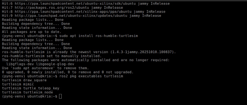
If the installation was successful, you should see entries like turtlesim_node, turtle_teleop_key, and others.
Setting Up Remote Access for KR260
To set up graphical remote access to the KR260, or any Ubuntu-based embedded platform, TigerVNC can installed and configured as a lightweight VNC server. TigerVNC offers a virtual X11 desktop that remote machines can access with standard VNC clients.
To enable remote desktop access on the KRIA board running Ubuntu 22.04, start by updating and installing the TigerVNC server package using
sudo apt update
sudo apt install tigervnc-standalone-server tigervnc-common
Once the installation is completed, the initial VNC session was created using
tigervncserver :1 -xstartup /usr/bin/startxfce4
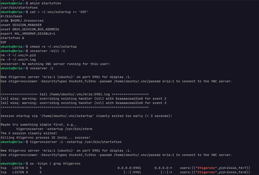
Then, install the TigerVNC Viewer on the host system using
sudo apt install tigervnc-viewer -y
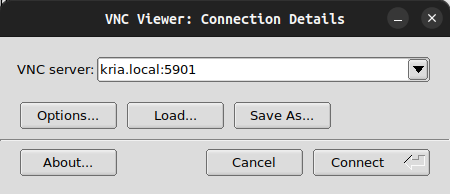
then, launch the viewer with the following settings to connect to the VNC Server on KR260.
Installing Drivers for Wireless USB Adapter via DKMS
Connecting to the KR260 via the Ethernet (RJ45)cable limits the mobility of the device.To make it more mobile Wireless USB Adapter is used to provide connectivity for LAN and internet access for installing and updating the packages in it.My wireless USB adapter is having Realtek RTL8822BU chipset so, I'll be installing the Realtek RTL88x2BU WiFi USB driver using DKMS.
First make sure that make sure of having the essential packages like DKMS, Git, build tools, and kernel headers installed.
Once the system is set up, clone the driver source into the DKMS module directory using the command
git clone "https://github.com/RinCat/RTL88x2BU-Linux-Driver.git" /usr/src/rtl88x2bu-git
After cloning the repository, update the module’s DKMS configuration file so that it correctly identifies the version. Do this by changing the PACKAGE_VERSION field in dkms.conf with the command
sed -i 's/PACKAGE_VERSION="@PKGVER@"/PACKAGE_VERSION="git"/g' /usr/src/rtl88x2bu-git/dkms.conf
With the configuration file updated, the next step is to register the driver with DKMS so it can be built and managed automatically. Add it to DKMS by running
dkms add -m rtl88x2bu -v git
This tells DKMS about the module’s name and version. After successfully adding the module, move on to building and installing it with the command
dkms autoinstall
After the installation is done, the WiFi Connectivity is enabled on the KR260 which is accessible via the settings app, select the required WiFi AP and enter the credentials to connect to it.
Finally the initial setup is complete for the KR260.
Trying out the CIFAR10 Model
To initially try out if the DPU is perfectly setup and to check VART 3.5 is working or not I used the modified app_cifar10_tf2_resnet18.py application code to run inference with the modified ResNet18 on the webcam feed.I followed the instructions to compile the quantized model.
Here's the python code for the to run inference with the modified ResNet18 on the webcam feed.Just clone the repo and copy it into the "Kria-RoboticsAI/files/cifar10_tf2" folder and run it.
print(" ")
print("ResNet18 CNN - CIFAR10 Classifier")
print("Real-time Webcam Inference with Display")
print(" ")
# ***********************************************************************
# import Packages
# ***********************************************************************
import os
import time
import numpy as np
import cv2
# ***********************************************************************
# input file names
# ***********************************************************************
cnn_xmodel = os.path.join("./compiled", "kr260_cifar10_tf2_resnet18.xmodel")
# ***********************************************************************
# utility Functions
# ***********************************************************************
def calculate_softmax(data):
    """Calculate softmax and return normalized probabilities"""
    exp_data = np.exp(data - np.max(data))  # Subtract max for numerical stability
    return exp_data / exp_data.sum()
def Normalize(image):
    """Normalize image to match training preprocessing"""
    x_test = np.asarray(image)
    x_test = x_test.astype(np.float32)
    x_test = x_test / 255.0
    x_test = x_test - 0.5
    out_x_test = x_test * 2
    return out_x_test
# ***********************************************************************
# cifar10 labels
# ***********************************************************************
label_list = ['airplane', 'automobile', 'bird', 'cat', 'deer',
              'dog', 'frog', 'horse', 'ship', 'truck']
# ***********************************************************************
# prepare the Overlay and load the "cnn.xmodel"
# ***********************************************************************
from pynq_dpu import DpuOverlay
print("Loading DPU overlay and model...")
overlay = DpuOverlay("dpu.bit")
overlay.load_model(cnn_xmodel)
# ***********************************************************************
# use python VART APIs
# ***********************************************************************
dpu = overlay.runner
inputTensors = dpu.get_input_tensors()
outputTensors = dpu.get_output_tensors()
shapeIn = tuple(inputTensors[0].dims)
shapeOut = tuple(outputTensors[0].dims)
outputSize = int(outputTensors[0].get_data_size() / shapeIn[0])
print("shapeIn   : {}".format(shapeIn))
print("shapeOut  : {}".format(shapeOut))
print("outputSize: {}".format(outputSize))
# allocate some buffers that will be re-used multiple times
output_data = [np.empty(shapeOut, dtype=np.float32, order="C")]
input_data = [np.empty(shapeIn, dtype=np.float32, order="C")]
image_buffer = input_data[0]
print("\nModel loaded successfully!")
# ***********************************************************************
# real-time Webcam Inference with Continuous Detection
# ***********************************************************************
def run_webcam_continuous(dpu, input_data, output_data, shapeIn, outputSize, confidence_threshold=0.3):
    """
    arguments:
        dpu: DPU runner object
        input_data: Pre-allocated input buffer
        output_data: Pre-allocated output buffer
        shapeIn: Input tensor shape
        outputSize: Output tensor size
        confidence_threshold: Minimum confidence to show prediction
    """
    cap = cv2.VideoCapture(0) # webcam stream
    if not cap.isOpened():
        print("Error: Could not open webcam")
        return
    cap.set(cv2.CAP_PROP_FRAME_WIDTH, 640)
    cap.set(cv2.CAP_PROP_FRAME_HEIGHT, 480)
    cap.set(cv2.CAP_PROP_FPS, 30)
    print("\n" + "="*60)
    print("Real-time Webcam Inference")
    print("="*60)
    print("Press 'q' to quit")
    print("Press 's' to save current frame")
    print("Press 'c' to toggle continuous/manual mode")
    print(f"Confidence threshold: {confidence_threshold:.0%}")
    print("="*60 + "\n")
    # get reference to the image array
    image = input_data[0]
    # warm up camera
    print("Warming up camera...")
    for _ in range(30):
        cap.read()
    # performance tracking
    frame_count = 0
    fps_start = time.time()
    fps = 0
    # continuous or manual mode
    continuous_mode = True
    last_prediction = None
    last_confidence = 0
    # create windows
    cv2.namedWindow('CIFAR10 Webcam Classifier', cv2.WINDOW_NORMAL)

    print("Starting inference...")

    while True:
        # capture frame
        ret, frame = cap.read()
        if not ret:
            print("Error: Failed to capture frame")
            break
        # create display frame
        display_frame = frame.copy()
        #only run inference in continuous mode or when capturing
        if continuous_mode:
            #resize frame to 32x32 (CIFAR10 size)
            resized = cv2.resize(frame, (32, 32), interpolation=cv2.INTER_AREA)
            #preprocess the image
            preprocessed = Normalize(resized)
            # ensuring the correct shape
            image[0, ...] = preprocessed.reshape(shapeIn[1:])
            #run inference on DPU
            inference_start = time.time()
            job_id = dpu.execute_async(input_data, output_data)
            dpu.wait(job_id)
            inference_time = (time.time() - inference_start) * 1000
            #get results
            temp = [j.reshape(1, outputSize) for j in output_data]
            softmax_raw = temp[0][0]
            #calculate normalized softmax probabilities
            softmax = calculate_softmax(softmax_raw)
            prediction_idx = softmax.argmax()
            confidence = softmax[prediction_idx]
            #store prediction
            last_prediction = prediction_idx
            last_confidence = confidence
            #calculate FPS
            frame_count += 1
            if frame_count % 30 == 0:
                fps = 30 / (time.time() - fps_start)
                fps_start = time.time()

        #sisplay information on frame
        if last_prediction is not None:
            predicted_label = label_list[last_prediction]
            #color based on confidence
            if last_confidence >= 0.7:
                color = (0, 255, 0)  # Green - high confidence
            elif last_confidence >= 0.4:
                color = (0, 255, 255)  # Yellow - medium confidence
            else:
                color = (0, 165, 255)  # Orange - low confidence
            #main prediction
            cv2.putText(display_frame, f"Prediction: {predicted_label}",
                       (10, 40), cv2.FONT_HERSHEY_SIMPLEX, 1.0, color, 2)
            cv2.putText(display_frame, f"Confidence: {last_confidence:.1%}",
                       (10, 75), cv2.FONT_HERSHEY_SIMPLEX, 0.8, color, 2)
            #warning for low confidence
            if last_confidence < confidence_threshold:
                cv2.putText(display_frame, "LOW CONFIDENCE",
                           (10, 110), cv2.FONT_HERSHEY_SIMPLEX, 0.7, (0, 0, 255), 2)

        #display stats
        mode_text = "CONTINUOUS" if continuous_mode else "MANUAL"
        cv2.putText(display_frame, f"Mode: {mode_text}",
                   (10, display_frame.shape[0] - 70), cv2.FONT_HERSHEY_SIMPLEX, 0.6, (255, 255, 255), 2)
        cv2.putText(display_frame, f"FPS: {fps:.1f}",
                   (10, display_frame.shape[0] - 40), cv2.FONT_HERSHEY_SIMPLEX, 0.6, (255, 255, 255), 2)
        cv2.putText(display_frame, f"Inference: {inference_time:.1f}ms" if continuous_mode else "Inference: N/A",
                   (10, display_frame.shape[0] - 10), cv2.FONT_HERSHEY_SIMPLEX, 0.6, (255, 255, 255), 2)


        cv2.putText(display_frame, "Q:Quit | S:Save | C:Toggle Mode",
                   (display_frame.shape[1] - 380, display_frame.shape[0] - 10),
                   cv2.FONT_HERSHEY_SIMPLEX, 0.5, (200, 200, 200), 1)
        cv2.imshow('CIFAR10 Webcam Classifier', display_frame)
        key = cv2.waitKey(1) & 0xFF
        if key == ord('q'):
            print("\nExiting...")
            break
        elif key == ord('s'):
            timestamp = time.strftime("%Y%m%d_%H%M%S")
            filename = f"capture_{timestamp}_{label_list[last_prediction] if last_prediction is not None else 'unknown'}.jpg"
            cv2.imwrite(filename, display_frame)
            print(f"Saved: {filename}")
        elif key == ord('c'):
            continuous_mode = not continuous_mode
            mode = "CONTINUOUS" if continuous_mode else "MANUAL"
            print(f"Switched to {mode} mode")

    cap.release()
    cv2.destroyAllWindows()
    print("\nCamera closed.")
# ***********************************************************************
# information for running the model (just to remind during the run)
# ***********************************************************************
print("\nIMPORTANT NOTE:")
print("CIFAR10 is trained on 32x32 low-resolution images of:")
print("  - Vehicles: airplanes, automobiles, ships, trucks")
print("  - Animals: birds, cats, deer, dogs, frogs, horses")
print("\nFor best results:")
print("  1. Show clear, centered objects")
print("  2. Good lighting conditions")
print("  3. Objects should fill most of the frame")
print("  4. Model works best on objects similar to CIFAR10 training data")
print("")

#run with confidence threshold of 30%
run_webcam_continuous(dpu, input_data, output_data, shapeIn, outputSize, confidence_threshold=0.3)

# ***********************************************************************
# clean up **Important for running the next models or else need to reboot
# ***********************************************************************
del overlay
del dpu
print("\nCleanup complete.")
Here's the results for the CIFAR10 :
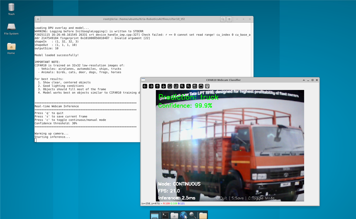
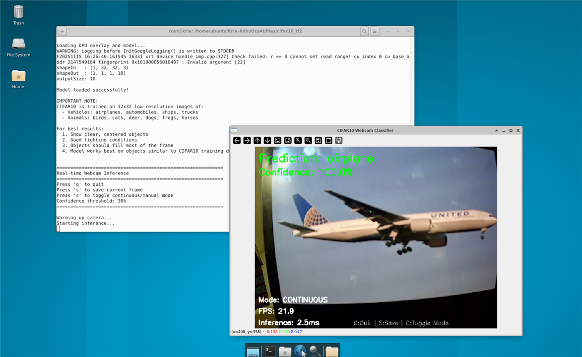
And it worked without any errors, so both the DPU and the VART 3.5 are setup without any major issues.
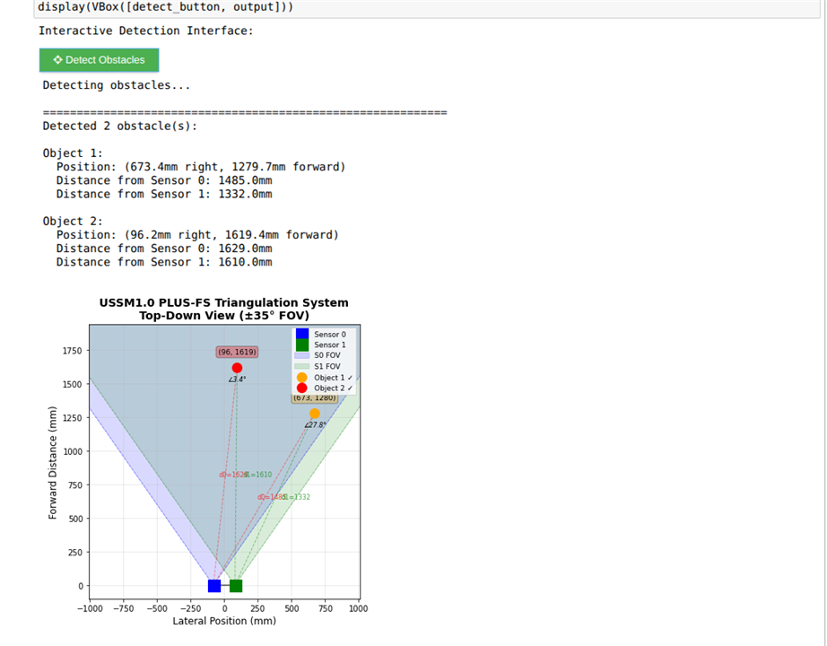
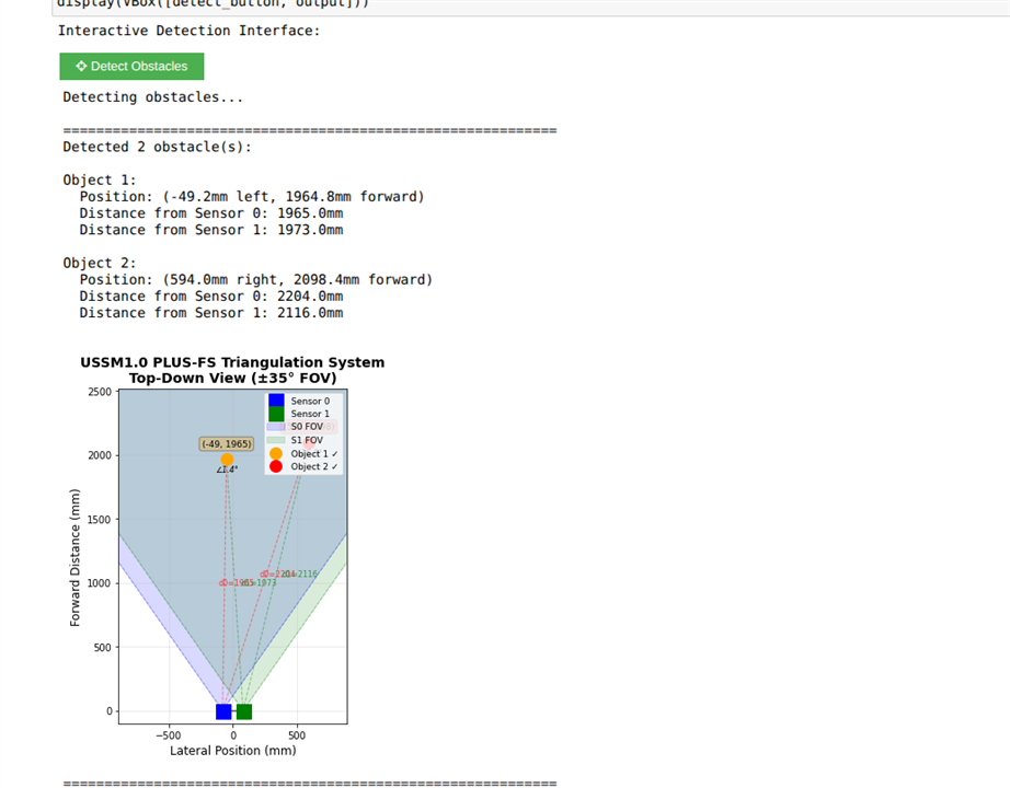
Testing the Multi-Object Detection using the USSM's
I tried to use triangulation based detection for multiple obstacles with USSMs and the demo kit. This method relied on the Send/Receive command with measurement profile A. Unfortunately, it didn't make it into the final version along with the YoloV3, because the calculations greatly lowered the FPS. I plan to test a more efficient implementation using the C++ VART APIs in the near future.
Testing the YoloV3 model with Distance Sensing
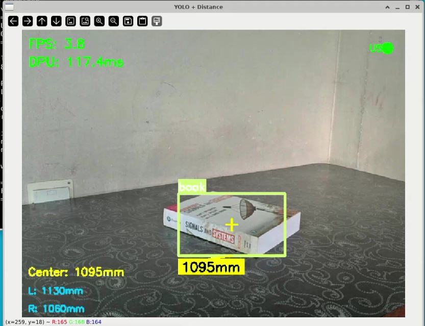
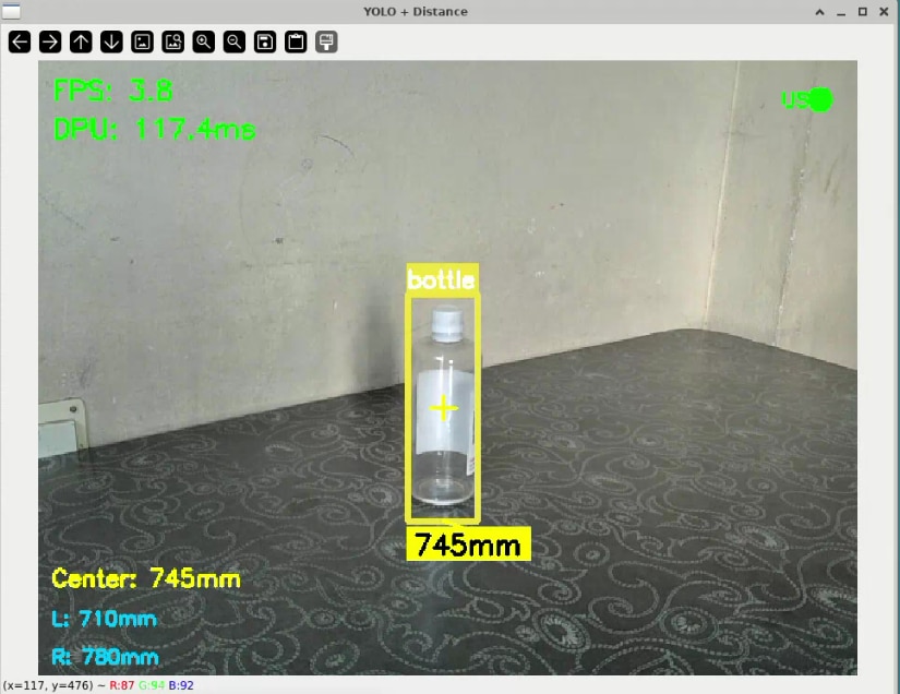
I tested how well YOLOv3 object detection works with ultrasonic distance measurements to achieve accurate object identification and spatial awareness. For this, I set up the system so the USB camera feed goes through the YOLOv3 model running on the KR260, which identifies and classifies objects in view. At the same time, the TDK USSM sensors measure the distances to these detected objects.
For the model deployment, I was lucky that the DPU bitstream compatible with VART 3.5 was already available and didn't need any regeneration. I created the .xmodel file using the Vitis AI Docker Image by following instructions from a useful hackster.io project, which provided great insights on how to quantize and prune the YOLOv3 PyTorch model. I obtained the coco.names file with all the object labels from the official darknet repository. For the USSM sensor setup, I used stream-out mode with a polling rate of 50Hz to get continuous real-time distance data.
To work on the system remotely, I created a script called env_disp_setup.sh that sets up the GUI display over X-session, allowing me to access it from anywhere in my local network. After switching to root user with sudo su, the script runs commands to configure the display environment properly.Here's the content of the script file
$ source /etc/profile.d/pynq_venv.sh
$ export DISPLAY=:1
$ export XAUTHORITY=/home/ubuntu/.Xauthority
$ xhost +local:
During testing, I placed various objects at different distances from the setup to check how accurately the system detects objects and measures their distances. The display showed bounding boxes around detected objects along with real time distance readings from the USSM sensors.
Here's the python code for it
# YOLOv3 and TDK USSM Ultrasonic Distance Fusion
# combines YOLOv3 object detection with 2 USSMs to display both object class and realtime distance.
# 'streamout' mode is used for continuous,low latency ultrasonic data.
print("="*60)
print("YOLOv3 + Ultrasonic Distance Fusion")
print("Using DPU and TDK's USSM Sensors")
print("="*60)
# ***********************************************************************
# import Packages
# ***********************************************************************
import os
import time
import numpy as np
import cv2
import random
from threading import Thread
import serial
import re
# ***********************************************************************
# configuration
# ***********************************************************************
MODEL_PATH = "kr260_yoloV3.xmodel"
DPU_BIT = "dpu.bit"
CLASSES_PATH = "coco.names"
#ultrasonic sensor configuration
SENSOR_PORT = '/dev/ttyUSB0'  # default for TDK demo kit for kr260 setup with the same hardware i connected
SENSOR_BAUDRATE = 115200
CONFIG = { # yoloV3 configuration
    "img_h": 416, #max as per the .xmodel params suggested in the AMD forum post
    "img_w": 416,
    "confidence_threshold": 0.6,
    "nms_threshold": 0.45,
    "yolo": {
        "anchors": np.array([
            [[116, 90], [156, 198], [373, 326]],
            [[30, 61], [62, 45], [59, 119]],
            [[10, 13], [16, 30], [33, 23]]
        ]),
        "classes": 80,
    }
}
# ***********************************************************************
# tdk's USSM interface
# ***********************************************************************
class UltrasonicSensor:
    def __init__(self, port, baudrate=115200):
        self.port = port
        self.baudrate = baudrate
        self.ser = None
        self.streaming = False
        self.stopped = True
        self.sensor0_dist = None
        self.sensor1_dist = None
        self.center_dist = None
        self.last_update = 0
        self.connect()
    def connect(self):
        try:
            self.ser = serial.Serial(self.port, self.baudrate, timeout=0.1)
            time.sleep(0.5)
            self.ser.reset_input_buffer()
            self._send_command("wkp[0x3]")
            time.sleep(0.3)
            print("Ultrasonic sensors connected and awake.")
            return True
        except Exception as e:
            print(f"Could not connect to ultrasonic sensors: {e}")
            return False
    def _send_command(self, cmd: str):
        #sends a command to the sensor board, ensuring it's properly terminated.
        if self.ser and self.ser.is_open:
            full_cmd = cmd.strip()
            if not full_cmd.endswith(';'):
                full_cmd += ' ;'
            self.ser.write(full_cmd.encode('ascii'))
            self.ser.flush()
            time.sleep(0.05)

    def start_streaming(self, stream_delay_ms: int = 50):
        #start continuous distance streaming in a background thread
        if not self.ser:
            print("Cannot start streaming, not connected.")
            return False
        # 'sto' command from the reference manual:
        # sto [SensorSelect] [<NSamples>] [<Delay>]
        # SensorSelect: [0x3] for Sensor 0 and 1.
        # NSamples: -1 for continuous streaming.
        # Delay: 50 for 50ms delay (~20 Hz), which is great for real-time fusion.
        cmd = f"sto[0x3] -1 {stream_delay_ms}"
        self._send_command(cmd)
        self.streaming = True
        self.stopped = False
        Thread(target=self._read_stream, daemon=True).start()
        print(f"Ultrasonic streaming started with command: '{cmd};'")
        return True
    def _read_stream(self):
        #background thread function to continuously read and parse stream data
        while not self.stopped:
            try:
                if self.ser and self.ser.in_waiting:
                    line = self.ser.readline().decode('ascii', errors='ignore').strip()

                    if line and line != '#':
                        parts = line.split()

                        if len(parts) >= 2:
                            try:
                                dist0_cm = float(parts[0])
                                dist1_cm = float(parts[1])

                                # A value of 0 indicates Near Field Detection (object too close)
                                self.sensor0_dist = dist0_cm * 10.0 if dist0_cm > 0 else None
                                self.sensor1_dist = dist1_cm * 10.0 if dist1_cm > 0 else None

                                if self.sensor0_dist and self.sensor1_dist:
                                    self.center_dist = (self.sensor0_dist + self.sensor1_dist) / 2.0
                                elif self.sensor0_dist:
                                    self.center_dist = self.sensor0_dist
                                elif self.sensor1_dist:
                                    self.center_dist = self.sensor1_dist
                                else:
                                    self.center_dist = None

                                self.last_update = time.time()
                            except ValueError:
                                pass

                time.sleep(0.005)
            except (serial.SerialException, OSError):
                print("\nSensor disconnected during streaming. Thread stopping.")
                self.stopped = True
                break

    def get_distance(self):
        #Get the last calculated center distance. Returns None if data is stale
        if self.stopped or (time.time() - self.last_update) > 0.5:
            return None
        return self.center_dist

    def get_both_distances(self):
        #Get individual sensor distances. Returns (None, None) if data is stale
        if self.stopped or (time.time() - self.last_update) > 0.5:
            return None, None
        return self.sensor0_dist, self.sensor1_dist

    def stop(self):
        #stops the streaming thread, terminates the sensor stream, and closes the port
        if self.stopped:
            return

        self.stopped = True

        if self.streaming and self.ser and self.ser.is_open:
            try:
                print("\nStopping sensor stream...")
                self._send_command("end")
                time.sleep(0.2)
                self._send_command("std[0x3]") #puts sensors into low-power standby
                time.sleep(0.2)
            except Exception as e:
                print(f"Warning: Could not send stop commands cleanly: {e}")

        if self.ser and self.ser.is_open:
            self.ser.close()

        print("Ultrasonic sensors stopped and disconnected.")

# ***********************************************************************
# threaded Webcam Class
# ***********************************************************************
class WebcamVideoStream:
    # (This class is kept exactly as you provided it)
    def __init__(self, src=0):
        self.stream = cv2.VideoCapture(src)
        if not self.stream.isOpened():
            raise IOError("Cannot open webcam")
        self.stream.set(cv2.CAP_PROP_FRAME_WIDTH, 640)
        self.stream.set(cv2.CAP_PROP_FRAME_HEIGHT, 480)
        self.stream.set(cv2.CAP_PROP_FPS, 30)
        self.stream.set(cv2.CAP_PROP_BUFFERSIZE, 1)
        (self.grabbed, self.frame) = self.stream.read()
        self.stopped = False
    def start(self):
        Thread(target=self.update, args=(), daemon=True).start()
        return self
    def update(self):
        while not self.stopped:
            (self.grabbed, self.frame) = self.stream.read()
    def read(self):
        return self.frame
    def stop(self):
        self.stopped = True
        self.stream.release()
# ***********************************************************************
# utility & post-processing
# ***********************************************************************
def sigmoid(x):
    return 1 / (1 + np.exp(-np.clip(x, -50, 50)))
def exp_safe(x):
    return np.exp(np.clip(x, -50, 50))
class YOLOPost:
    def __init__(self, anchors, num_classes, img_size):
        self.anchors = anchors; self.num_anchors = len(anchors); self.num_classes = num_classes
        self.bbox_attrs = 5 + num_classes; self.img_size = img_size
    def forward(self, input_data):
        bs, _, in_h, in_w = input_data.shape
        stride_h = self.img_size[1] / in_h; stride_w = self.img_size[0] / in_w
        scaled_anchors = np.array([(a_w / stride_w, a_h / stride_h) for a_w, a_h in self.anchors])
        prediction = input_data.reshape(bs, self.num_anchors, self.bbox_attrs, in_h, in_w).transpose(0, 1, 3, 4, 2)
        x = sigmoid(prediction[..., 0]); y = sigmoid(prediction[..., 1]); w = prediction[..., 2]; h = prediction[..., 3]
        conf = sigmoid(prediction[..., 4]); pred_cls = sigmoid(prediction[..., 5:])
        grid_x = np.arange(in_w).reshape(1, 1, 1, in_w); grid_y = np.arange(in_h).reshape(1, 1, in_h, 1)
        anchor_w = scaled_anchors[:, 0].reshape(1, self.num_anchors, 1, 1)
        anchor_h = scaled_anchors[:, 1].reshape(1, self.num_anchors, 1, 1)
        pred_boxes = np.empty_like(prediction[..., :4])
        pred_boxes[..., 0] = (x + grid_x) * stride_w; pred_boxes[..., 1] = (y + grid_y) * stride_h
        pred_boxes[..., 2] = exp_safe(w) * anchor_w * stride_w; pred_boxes[..., 3] = exp_safe(h) * anchor_h * stride_h
        output = np.concatenate((pred_boxes.reshape(bs, -1, 4), conf.reshape(bs, -1, 1), pred_cls.reshape(bs, -1, self.num_classes)), axis=-1)
        return output
def bbox_iou(box1, box2):
    b1_x1, b1_y1, b1_x2, b1_y2 = box1[0], box1[1], box1[2], box1[3]
    b2_x1, b2_y1, b2_x2, b2_y2 = box2[:, 0], box2[:, 1], box2[:, 2], box2[:, 3]
    inter_area = np.maximum(0, np.minimum(b1_x2, b2_x2) - np.maximum(b1_x1, b2_x1)) * np.maximum(0, np.minimum(b1_y2, b2_y2) - np.maximum(b1_y1, b2_y1))
    b1_area = (b1_x2 - b1_x1) * (b1_y2 - b1_y1); b2_area = (b2_x2 - b2_x1) * (b2_y2 - b2_y1)
    return inter_area / (b1_area + b2_area - inter_area + 1e-16)
def non_max_suppression(prediction, num_classes, conf_thres, nms_thres):
    box_corner = np.empty_like(prediction); box_corner[:, 0] = prediction[:, 0] - prediction[:, 2] / 2
    box_corner[:, 1] = prediction[:, 1] - prediction[:, 3] / 2; box_corner[:, 2] = prediction[:, 0] + prediction[:, 2] / 2
    box_corner[:, 3] = prediction[:, 1] + prediction[:, 3] / 2; prediction[:, :4] = box_corner[:, :4]
    prediction = prediction[prediction[:, 4] >= conf_thres]
    if not prediction.shape[0]: return []
    class_conf = np.max(prediction[:, 5:5 + num_classes], axis=1, keepdims=True)
    class_pred = np.argmax(prediction[:, 5:5 + num_classes], axis=1, keepdims=True)
    detections = np.concatenate((prediction[:, :5], class_conf, class_pred.astype(np.float32)), 1)
    unique_labels = np.unique(detections[:, -1]); all_max_detections = []
    for c in unique_labels:
        detections_class = detections[detections[:, -1] == c]
        conf_sort_index = np.argsort(detections_class[:, 4])[::-1]
        detections_class = detections_class[conf_sort_index]; max_detections_class = []
        while detections_class.shape[0]:
            max_detections_class.append(detections_class[0].tolist())
            if len(detections_class) == 1: break
            ious = bbox_iou(detections_class[0, :4], detections_class[1:, :4])
            detections_class = detections_class[1:][ious < nms_thres]
        all_max_detections.extend(max_detections_class)
    return all_max_detections
# ***********************************************************************
# drawing with distance
# ***********************************************************************
def draw_detections_with_distance(frame, detections, classes, distance_mm, dist0, dist1):
    if not detections:
        if distance_mm: cv2.putText(frame, f"Center: {distance_mm:.0f}mm", (10, frame.shape[0] - 70), cv2.FONT_HERSHEY_SIMPLEX, 0.6, (0, 255, 255), 2)
        if dist0: cv2.putText(frame, f"L: {dist0:.0f}mm", (10, frame.shape[0] - 40), cv2.FONT_HERSHEY_SIMPLEX, 0.5, (255, 200, 0), 2)
        if dist1: cv2.putText(frame, f"R: {dist1:.0f}mm", (10, frame.shape[0] - 10), cv2.FONT_HERSHEY_SIMPLEX, 0.5, (255, 200, 0), 2)
        return frame
    colors = {cls: (random.randint(50, 255), random.randint(50, 255), random.randint(50, 255)) for cls in range(len(classes))}
    frame_h, frame_w = frame.shape[:2]; frame_center_x = frame_w / 2; frame_center_y = frame_h / 2
    closest_detection = None; min_distance_to_center = float('inf')
    for det in detections:
        x1, y1, x2, y2 = det[:4]; box_center_x = (x1 + x2) / 2; box_center_y = (y1 + y2) / 2
        dist_to_center = np.sqrt((box_center_x - frame_center_x)**2 + (box_center_y - frame_center_y)**2)
        if dist_to_center < min_distance_to_center: min_distance_to_center = dist_to_center; closest_detection = det
    for det in detections:
        x1, y1, x2, y2, _, _, cls_pred = det; cls_id = int(cls_pred)
        if cls_id >= len(classes): continue
        color = colors.get(cls_id, (0, 255, 0)); is_closest = (det == closest_detection) if closest_detection else False
        thickness = 3 if is_closest else 2; cv2.rectangle(frame, (int(x1), int(y1)), (int(x2), int(y2)), color, thickness)
        label = f"{classes[cls_id]}"; (label_w, label_h), _ = cv2.getTextSize(label, cv2.FONT_HERSHEY_SIMPLEX, 0.6, 2)
        cv2.rectangle(frame, (int(x1), int(y1) - label_h - 10), (int(x1) + label_w, int(y1)), color, -1)
        cv2.putText(frame, label, (int(x1), int(y1) - 5), cv2.FONT_HERSHEY_SIMPLEX, 0.6, (255, 255, 255), 2)
        if is_closest and distance_mm:
            dist_label = f"{distance_mm:.0f}mm"; (dist_w, dist_h), _ = cv2.getTextSize(dist_label, cv2.FONT_HERSHEY_SIMPLEX, 0.7, 2)
            dist_y = int(y2) + dist_h + 10; cv2.rectangle(frame, (int(x1), dist_y - dist_h - 5), (int(x1) + dist_w + 10, dist_y + 5), (0, 255, 255), -1)
            cv2.putText(frame, dist_label, (int(x1) + 5, dist_y), cv2.FONT_HERSHEY_SIMPLEX, 0.7, (0, 0, 0), 2)
            cv2.line(frame, (int((x1 + x2) / 2), int(y2)), (int(x1) + dist_w // 2, dist_y - dist_h - 5), (0, 255, 255), 2)
        if is_closest: cv2.drawMarker(frame, (int((x1 + x2) / 2), int((y1 + y2) / 2)), (0, 255, 255), cv2.MARKER_CROSS, 20, 2)
    if distance_mm: cv2.putText(frame, f"Center: {distance_mm:.0f}mm", (10, frame.shape[0] - 70), cv2.FONT_HERSHEY_SIMPLEX, 0.6, (0, 255, 255), 2)
    if dist0: cv2.putText(frame, f"L: {dist0:.0f}mm", (10, frame.shape[0] - 40), cv2.FONT_HERSHEY_SIMPLEX, 0.5, (255, 200, 0), 2)
    if dist1: cv2.putText(frame, f"R: {dist1:.0f}mm", (10, frame.shape[0] - 10), cv2.FONT_HERSHEY_SIMPLEX, 0.5, (255, 200, 0), 2)
    return frame
def scale_boxes(detections, frame_shape, model_shape):
    if not detections: return []
    ori_h, ori_w = frame_shape; model_h, model_w = model_shape
    scaled_detections = np.array(detections); x_scale = ori_w / model_w; y_scale = ori_h / model_h
    scaled_detections[:, 0] *= x_scale; scaled_detections[:, 2] *= x_scale
    scaled_detections[:, 1] *= y_scale; scaled_detections[:, 3] *= y_scale
    return scaled_detections.tolist()
# ***********************************************************************
# main inference Loop
# ***********************************************************************
def run_fused_inference():
    print("Loading class names...")
    try:
        with open(CLASSES_PATH, 'r') as f:
            classes = [line.strip() for line in f.readlines() if line.strip()]
        print(f"Loaded {len(classes)} classes")
    except FileNotFoundError:
        print(f"Class names file not found: {CLASSES_PATH}")
        return
    print("\nLoading DPU overlay and model...")
    try:
        from pynq_dpu import DpuOverlay
        overlay = DpuOverlay(DPU_BIT)
        overlay.load_model(MODEL_PATH)
        print("DPU overlay and model loaded")
    except Exception as e:
        print(f"Failed to load DPU overlay: {e}")
        return
    dpu = overlay.runner
    inputTensors = dpu.get_input_tensors(); outputTensors = dpu.get_output_tensors()
    shapeIn = tuple(inputTensors[0].dims); output_shapes = [tuple(tensor.dims) for tensor in outputTensors]
    input_data = [np.empty(shapeIn, dtype=np.float32, order="C")]
    output_data = [np.empty(shape, dtype=np.float32, order="C") for shape in output_shapes]
    yolo_processors = [YOLOPost(CONFIG["yolo"]["anchors"][i], CONFIG["yolo"]["classes"], (CONFIG["img_w"], CONFIG["img_h"])) for i in range(3)]
    print("\nInitializing ultrasonic sensors...")
    ultrasonic = UltrasonicSensor(SENSOR_PORT, SENSOR_BAUDRATE)
    if not ultrasonic.start_streaming():
        print("Continuing without ultrasonic distance measurements.")
        ultrasonic = None
    print("\nStarting webcam...")
    cap = WebcamVideoStream(src=0).start()
    time.sleep(1) # Allow camera to warm up
    print("\n" + "="*60 + "\nSTARTING FUSED INFERENCE\n" + "="*60 + "\nPress 'q' to quit\n")
    frame_count = 0; fps_start_time = time.time(); fps = 0; inference_times = []
    cv2.namedWindow('YOLO + Distance', cv2.WINDOW_NORMAL)
    cv2.resizeWindow('YOLO + Distance', 960, 720)

    try:
        while True:
            frame = cap.read()
            if frame is None: continue
            image_resized = cv2.resize(frame, (CONFIG["img_w"], CONFIG["img_h"]))
            image_rgb = cv2.cvtColor(image_resized, cv2.COLOR_BGR2RGB)
            input_data[0][0] = image_rgb.astype(np.float32) / 255.0
            inference_start = time.time()
            job_id = dpu.execute_async(input_data, output_data); dpu.wait(job_id)
            inference_times.append((time.time() - inference_start) * 1000)
            if len(inference_times) > 30: inference_times.pop(0)
            output_list = [yolo_processors[i].forward(np.transpose(output_data[i], (0, 3, 1, 2))) for i in range(3)]
            output_combined = np.concatenate(output_list, axis=1)
            detections = non_max_suppression(output_combined[0], CONFIG["yolo"]["classes"],
                                             conf_thres=CONFIG["confidence_threshold"], nms_thres=CONFIG["nms_threshold"])
            scaled_detections = scale_boxes(detections, frame.shape[:2], (CONFIG["img_h"], CONFIG["img_w"]))
            distance_mm, (dist0, dist1) = (None, (None, None))
            if ultrasonic:
                distance_mm = ultrasonic.get_distance()
                dist0, dist1 = ultrasonic.get_both_distances()
            display_frame = draw_detections_with_distance(frame, scaled_detections, classes, distance_mm, dist0, dist1)
            if time.time() - fps_start_time > 1:
                fps = frame_count / (time.time() - fps_start_time)
                frame_count = 0; fps_start_time = time.time()
            frame_count += 1
            cv2.putText(display_frame, f"FPS: {fps:.1f}", (10, 30), cv2.FONT_HERSHEY_SIMPLEX, 0.7, (0, 255, 0), 2)
            cv2.putText(display_frame, f"DPU: {np.mean(inference_times):.1f}ms", (10, 60), cv2.FONT_HERSHEY_SIMPLEX, 0.7, (0, 255, 0), 2)
            sensor_status = ultrasonic.get_distance() if ultrasonic else None
            sensor_color = (0, 255, 0) if sensor_status is not None else (0, 0, 255)
            cv2.circle(display_frame, (display_frame.shape[1] - 30, 30), 10, sensor_color, -1)
            cv2.putText(display_frame, "US", (display_frame.shape[1] - 60, 35), cv2.FONT_HERSHEY_SIMPLEX, 0.5, sensor_color, 2)
            cv2.imshow('YOLO + Distance', display_frame)
            if cv2.waitKey(1) & 0xFF == ord('q'):
                break
    except KeyboardInterrupt:
        print("\nInterrupted by user.")
    finally:
        print("\nCleaning up...")
        cap.stop()
        if ultrasonic:
            ultrasonic.stop()
        cv2.destroyAllWindows()
        if 'overlay' in locals():
            del overlay
            del dpu
        print("Cleanup done.")

if __name__ == '__main__':
    run_fused_inference()
The YOLOv3 model identified objects accurately, and the USSM sensors provided reliable range data, but I noticed a problem: the frame rate was too low for smooth operation. To address this, I restructured the code using multi threading to run tasks in parallel. I created separate threads for the YOLOv3 processing and the ultrasonic sensor readings, while keeping the main thread focused only on displaying the video feed. This allowed the display GUI to update smoothly, even as the ML model inference is being processed in the background. I also used thread locks to safely share data between these parallel processes, ensuring the main display showed the most recent results without conflicts.
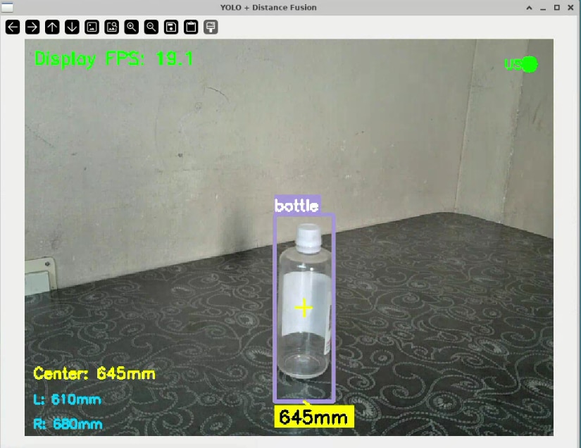
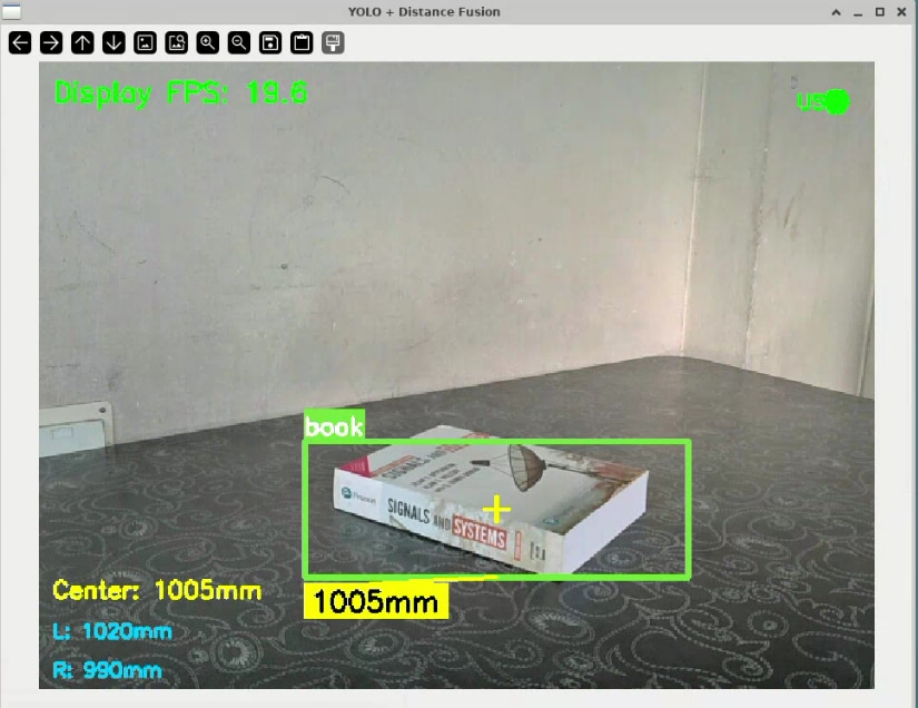
After these improvements, the results were quite satisfactory. The system reached around 20 FPS at its peak, providing smooth real-time object detection with synchronized distance measurements.
Here's the improvised python code:
print("="*60)
print("high-perf 20FPS max Vision-Sonar fusion")
print("="*60)
# ***********************************************************************
# import the required packages
# ***********************************************************************
import os
import sys
import time
import numpy as np
import cv2
import random
from threading import Thread, Lock
import serial
import re
import copy
# ***********************************************************************
# configuration
# ***********************************************************************
MODEL_PATH = "kr260_yoloV3.xmodel"
DPU_BIT = "dpu.bit"
CLASSES_PATH = "coco.names"
SENSOR_PORT = '/dev/ttyUSB0'
SENSOR_BAUDRATE = 115200
CONFIG = {
    "img_h": 416, "img_w": 416, "confidence_threshold": 0.6, "nms_threshold": 0.45,
    "yolo": { "anchors": np.array([[[116,90],[156,198],[373,326]],[[30,61],[62,45],[59,119]],[[10,13],[16,30],[33,23]]]), "classes": 80,}
}
latest_frame = {"frame": None, "lock": Lock()}
dpu_results = {"detections": [], "lock": Lock()}
stop_threads = False # A global flag to signal all threads to exit.
# ***********************************************************************
# yolo post-processing
# ***********************************************************************
def sigmoid(x):
    return 1 / (1 + np.exp(-np.clip(x, -50, 50)))

def exp_safe(x):
    return np.exp(np.clip(x, -50, 50))

def bbox_iou(box1, box2):
    b1_x1, b1_y1, b1_x2, b1_y2 = box1[0], box1[1], box1[2], box1[3]
    b2_x1, b2_y1, b2_x2, b2_y2 = box2[:, 0], box2[:, 1], box2[:, 2], box2[:, 3]
    inter_area = np.maximum(0, np.minimum(b1_x2, b2_x2) - np.maximum(b1_x1, b2_x1)) * \
                 np.maximum(0, np.minimum(b1_y2, b2_y2) - np.maximum(b1_y1, b2_y1))
    b1_area = (b1_x2 - b1_x1) * (b1_y2 - b1_y1)
    b2_area = (b2_x2 - b2_x1) * (b2_y2 - b2_y1)
    return inter_area / (b1_area + b2_area - inter_area + 1e-16)

class YOLOPost:
    def __init__(self, anchors, num_classes, img_size):
        self.anchors = anchors
        self.num_anchors = len(anchors)
        self.num_classes = num_classes
        self.bbox_attrs = 5 + num_classes
        self.img_size = img_size
    def forward(self, input_data):
        bs, _, in_h, in_w = input_data.shape
        stride_h, stride_w = self.img_size[1] / in_h, self.img_size[0] / in_w
        scaled_anchors = np.array([(a_w/stride_w, a_h/stride_h) for a_w, a_h in self.anchors])
        prediction = input_data.reshape(bs, self.num_anchors, self.bbox_attrs, in_h, in_w).transpose(0, 1, 3, 4, 2)

        x, y = sigmoid(prediction[..., 0]), sigmoid(prediction[..., 1])
        w, h = prediction[..., 2], prediction[..., 3]
        conf, pred_cls = sigmoid(prediction[..., 4]), sigmoid(prediction[..., 5:])

        grid_x = np.arange(in_w).reshape(1, 1, 1, in_w)
        grid_y = np.arange(in_h).reshape(1, 1, in_h, 1)
        anchor_w = scaled_anchors[:, 0].reshape(1, self.num_anchors, 1, 1)
        anchor_h = scaled_anchors[:, 1].reshape(1, self.num_anchors, 1, 1)

        pred_boxes = np.empty_like(prediction[..., :4])
        pred_boxes[..., 0] = (x + grid_x) * stride_w
        pred_boxes[..., 1] = (y + grid_y) * stride_h
        pred_boxes[..., 2] = exp_safe(w) * anchor_w * stride_w
        pred_boxes[..., 3] = exp_safe(h) * anchor_h * stride_h

        output = np.concatenate((
            pred_boxes.reshape(bs, -1, 4),
            conf.reshape(bs, -1, 1),
            pred_cls.reshape(bs, -1, self.num_classes)
        ), axis=-1)
        return output

def non_max_suppression(prediction, num_classes, conf_thres, nms_thres):
    box_corner = np.empty_like(prediction)
    box_corner[:, 0] = prediction[:, 0] - prediction[:, 2] / 2
    box_corner[:, 1] = prediction[:, 1] - prediction[:, 3] / 2
    box_corner[:, 2] = prediction[:, 0] + prediction[:, 2] / 2
    box_corner[:, 3] = prediction[:, 1] + prediction[:, 3] / 2
    prediction[:, :4] = box_corner[:, :4]
    prediction = prediction[prediction[:, 4] >= conf_thres]
    if not prediction.shape[0]: return []
    class_conf = np.max(prediction[:, 5:5+num_classes], axis=1, keepdims=True)
    class_pred = np.argmax(prediction[:, 5:5+num_classes], axis=1, keepdims=True)
    detections = np.concatenate((prediction[:, :5], class_conf, class_pred.astype(np.float32)), 1)
    unique_labels = np.unique(detections[:, -1])
    all_max_detections = []
    for c in unique_labels:
        detections_class = detections[detections[:, -1] == c]
        conf_sort_index = np.argsort(detections_class[:, 4])[::-1]
        detections_class = detections_class[conf_sort_index]
        max_detections_class = []
        while detections_class.shape[0]:
            max_detections_class.append(detections_class[0].tolist())
            if len(detections_class) == 1: break
            ious = bbox_iou(detections_class[0, :4], detections_class[1:, :4])
            detections_class = detections_class[1:][ious < nms_thres]
        all_max_detections.extend(max_detections_class)
    return all_max_detections

class UltrasonicSensor:
    def __init__(self, port, baudrate=115200):
        self.port, self.baudrate=port,baudrate; self.ser=None; self.streaming,self.stopped=False,True
        self.sensor0_dist,self.sensor1_dist,self.center_dist=None,None,None; self.last_update=0; self.connect()
    def connect(self):
        try:
            self.ser=serial.Serial(self.port,self.baudrate,timeout=0.1);time.sleep(0.5)
            self.ser.reset_input_buffer();self._send_command("wkp[0x3]");time.sleep(0.3)
            print("Ultrasonic sensors connected.");return True
        except Exception as e:print(f"Ultrasonic connection failed: {e}");return False
    def _send_command(self,cmd:str):
        if self.ser and self.ser.is_open:
            full_cmd=cmd.strip();
            if not full_cmd.endswith(';'):full_cmd+=' ;'
            self.ser.write(full_cmd.encode('ascii'));self.ser.flush();time.sleep(0.05)
    def start_streaming(self,stream_delay_ms:int=50):
        if not self.ser:return False
        cmd=f"sto[0x3] -1 {stream_delay_ms}"; self._send_command(cmd)
        self.streaming,self.stopped=True,False; Thread(target=self._read_stream,daemon=True).start()
        print(f"Ultrasonic streaming started ('{cmd};').");return True
    def _read_stream(self):
        while not self.stopped:
            try:
                if self.ser and self.ser.in_waiting:
                    line=self.ser.readline().decode('ascii',errors='ignore').strip()
                    if line and line!='#':
                        parts=line.split()
                        if len(parts)>=2:
                            try:
                                d0_cm,d1_cm=float(parts[0]),float(parts[1])
                                self.sensor0_dist=d0_cm*10.0 if d0_cm>0 else None
                                self.sensor1_dist=d1_cm*10.0 if d1_cm>0 else None
                                if self.sensor0_dist and self.sensor1_dist:self.center_dist=(self.sensor0_dist+self.sensor1_dist)/2.0
                                elif self.sensor0_dist:self.center_dist=self.sensor0_dist
                                elif self.sensor1_dist:self.center_dist=self.sensor1_dist
                                else:self.center_dist=None
                                self.last_update=time.time()
                            except ValueError:pass
                time.sleep(0.005)
            except Exception:self.stopped=True
    def get_distance(self):
        if self.stopped or(time.time()-self.last_update)>0.5:return None
        return self.center_dist
    def get_both_distances(self):
        if self.stopped or(time.time()-self.last_update)>0.5:return None,None
        return self.sensor0_dist,self.sensor1_dist
    def stop(self):
        if self.stopped:return
        self.stopped=True
        if self.streaming and self.ser and self.ser.is_open:
            try:self._send_command("end");time.sleep(0.2);self._send_command("std[0x3]");time.sleep(0.2)
            except Exception:pass
        if self.ser and self.ser.is_open:self.ser.close()
        print("Ultrasonic sensors stopped.")
# ***********************************************************************
#threaded webcam Class
# ***********************************************************************
class WebcamVideoStream:
    def __init__(self, src=0):
        self.stream = cv2.VideoCapture(src)
        if not self.stream.isOpened(): raise IOError("Cannot open webcam")
        self.stream.set(cv2.CAP_PROP_FRAME_WIDTH, 640); self.stream.set(cv2.CAP_PROP_FRAME_HEIGHT, 480)
        (self.grabbed, self.frame) = self.stream.read(); self.stopped = False
    def start(self): Thread(target=self.update, args=(), daemon=True).start(); return self
    def update(self):
        while not self.stopped and not stop_threads: (self.grabbed, self.frame) = self.stream.read()
    def read(self): return self.frame
    def stop(self): self.stopped = True; self.stream.release()

# ***********************************************************************
#DPU inf thread
# ***********************************************************************
def dpu_inference_worker(dpu, input_data, output_data, yolo_processors, model_shape):
    global latest_frame, dpu_results, stop_threads
    while not stop_threads:
        with latest_frame["lock"]: frame_to_process = latest_frame["frame"]
        if frame_to_process is None: time.sleep(0.01); continue
        image_resized=cv2.resize(frame_to_process,(CONFIG["img_w"],CONFIG["img_h"]))
        image_rgb=cv2.cvtColor(image_resized,cv2.COLOR_BGR2RGB)
        input_data[0][0,...]=image_rgb.astype(np.float32)/255.0
        job_id=dpu.execute_async(input_data,output_data); dpu.wait(job_id)
        output_list=[proc.forward(np.transpose(out,(0,3,1,2))) for proc,out in zip(yolo_processors,output_data)]
        output_combined=np.concatenate(output_list,axis=1)
        detections=non_max_suppression(output_combined[0],CONFIG["yolo"]["classes"],conf_thres=CONFIG["confidence_threshold"],nms_thres=CONFIG["nms_threshold"])
        with dpu_results["lock"]:
            dpu_results["detections"] = scale_boxes(detections, frame_to_process.shape[:2], model_shape)
    print("DPU worker thread has stopped.")
# ***********************************************************************
# drawing and scaling functons
# ***********************************************************************
def scale_boxes(detections, frame_shape, model_shape):
    if not detections: return []
    ori_h, ori_w = frame_shape; model_h, model_w = model_shape
    x_scale, y_scale = ori_w / model_w, ori_h / model_h
    scaled_detections = copy.deepcopy(detections)
    for det in scaled_detections:
        det[0] *= x_scale; det[2] *= x_scale
        det[1] *= y_scale; det[3] *= y_scale
    return scaled_detections
def draw_detections_with_distance(frame, detections, classes, distance_mm, dist0, dist1):
    if not detections:
        if distance_mm: cv2.putText(frame,f"Center: {distance_mm:.0f}mm",(10,frame.shape[0]-70),cv2.FONT_HERSHEY_SIMPLEX,0.6,(0,255,255),2)
        if dist0: cv2.putText(frame,f"L: {dist0:.0f}mm",(10,frame.shape[0]-40),cv2.FONT_HERSHEY_SIMPLEX,0.5,(255,200,0),2)
        if dist1: cv2.putText(frame,f"R: {dist1:.0f}mm",(10,frame.shape[0]-10),cv2.FONT_HERSHEY_SIMPLEX,0.5,(255,200,0),2)
        return frame
    colors={cls:(random.randint(50,255),random.randint(50,255),random.randint(50,255)) for cls in range(len(classes))}
    frame_h,frame_w=frame.shape[:2];frame_center_x,frame_center_y=frame_w/2,frame_h/2
    closest_detection=None;min_distance_to_center=float('inf')
    for det in detections:
        x1,y1,x2,y2=det[:4];box_center_x,box_center_y=(x1+x2)/2,(y1+y2)/2
        dist_to_center=np.sqrt((box_center_x-frame_center_x)**2+(box_center_y-frame_center_y)**2)
        if dist_to_center<min_distance_to_center:min_distance_to_center=dist_to_center;closest_detection=det
    for det in detections:
        x1,y1,x2,y2,_,_,cls_pred=det;cls_id=int(cls_pred)
        if cls_id>=len(classes):continue
        color=colors.get(cls_id,(0,255,0));is_closest=(det==closest_detection) if closest_detection else False
        thickness=3 if is_closest else 2;cv2.rectangle(frame,(int(x1),int(y1)),(int(x2),int(y2)),color,thickness)
        label=f"{classes[cls_id]}";(label_w,label_h),_=cv2.getTextSize(label,cv2.FONT_HERSHEY_SIMPLEX,0.6,2)
        cv2.rectangle(frame,(int(x1),int(y1)-label_h-10),(int(x1)+label_w,int(y1)),color,-1)
        cv2.putText(frame,label,(int(x1),int(y1)-5),cv2.FONT_HERSHEY_SIMPLEX,0.6,(255,255,255),2)
        if is_closest and distance_mm:
            dist_label=f"{distance_mm:.0f}mm";(dist_w,dist_h),_=cv2.getTextSize(dist_label,cv2.FONT_HERSHEY_SIMPLEX,0.7,2)
            dist_y=int(y2)+dist_h+10;cv2.rectangle(frame,(int(x1),dist_y-dist_h-5),(int(x1)+dist_w+10,dist_y+5),(0,255,255),-1)
            cv2.putText(frame,dist_label,(int(x1)+5,dist_y),cv2.FONT_HERSHEY_SIMPLEX,0.7,(0,0,0),2)
            cv2.line(frame,(int((x1+x2)/2),int(y2)),(int(x1)+dist_w//2,dist_y-dist_h-5),(0,255,255),2)
        if is_closest:cv2.drawMarker(frame,(int((x1+x2)/2),int((y1+y2)/2)),(0,255,255),cv2.MARKER_CROSS,20,2)
    if distance_mm:cv2.putText(frame,f"Center: {distance_mm:.0f}mm",(10,frame.shape[0]-70),cv2.FONT_HERSHEY_SIMPLEX,0.6,(0,255,255),2)
    if dist0:cv2.putText(frame,f"L: {dist0:.0f}mm",(10,frame.shape[0]-40),cv2.FONT_HERSHEY_SIMPLEX,0.5,(255,200,0),2)
    if dist1:cv2.putText(frame,f"R: {dist1:.0f}mm",(10,frame.shape[0]-10),cv2.FONT_HERSHEY_SIMPLEX,0.5,(255,200,0),2)
    return frame
# ***********************************************************************
# main
# ***********************************************************************
def run_fused_inference():
    global stop_threads
    print("Loading class names...");
    try:
        with open(CLASSES_PATH, 'r') as f:
            classes = [line.strip() for line in f.readlines() if line.strip()]
        print(f"Loaded {len(classes)} classes")
    except Exception as e:
        print(f"Failed to load class names: {e}"); return
    print("\nLoading DPU overlay and model...");
    try:
        from pynq_dpu import DpuOverlay
        overlay = DpuOverlay(DPU_BIT); overlay.load_model(MODEL_PATH)
        print("DPU overlay and model loaded")
    except Exception as e:
        print(f"Failed to load DPU: {e}"); return
    dpu=overlay.runner; inputTensors=dpu.get_input_tensors(); outputTensors=dpu.get_output_tensors()
    shapeIn=tuple(inputTensors[0].dims); output_shapes=[tuple(tensor.dims) for tensor in outputTensors]
    input_data=[np.empty(shapeIn, dtype=np.float32, order="C")]
    output_data=[np.empty(shape, dtype=np.float32, order="C") for shape in output_shapes]
    yolo_processors=[YOLOPost(CONFIG["yolo"]["anchors"][i], CONFIG["yolo"]["classes"], (CONFIG["img_w"],CONFIG["img_h"])) for i in range(3)]
    print("\nInitializing ultrasonic sensors...");
    ultrasonic = UltrasonicSensor(SENSOR_PORT, SENSOR_BAUDRATE)
    if not ultrasonic.ser:
        print("Continuing without ultrasonic measurements."); ultrasonic = None
    elif not ultrasonic.start_streaming():
        print("Failed to start stream. Continuing without ultrasonic measurements."); ultrasonic = None
    print("\nStarting webcam...");
    cap = WebcamVideoStream(src=0).start(); time.sleep(1)
    print("Starting DPU inference worker thread...")
    dpu_thread = Thread(target=dpu_inference_worker, args=(dpu, input_data, output_data, yolo_processors, (CONFIG["img_h"], CONFIG["img_w"])), daemon=True)
    dpu_thread.start()
    print("\n" + "="*60 + "\nSTARTING MAIN DISPLAY LOOP\n" + "="*60 + "\nPress 'q' to quit\n")
    fps_start_time=time.time(); frame_count=0; fps=0
    cv2.namedWindow('YOLO + Distance Fusion', cv2.WINDOW_NORMAL)
    cv2.resizeWindow('YOLO + Distance Fusion', 960, 720)
    try:
        while True:
            frame = cap.read()
            if frame is None: continue
            with latest_frame["lock"]:
                latest_frame["frame"] = frame
            with dpu_results["lock"]:
                current_detections = dpu_results["detections"]
            distance_mm, (dist0, dist1) = (None, (None, None))
            if ultrasonic:
                distance_mm = ultrasonic.get_distance()
                dist0, dist1 = ultrasonic.get_both_distances()
            display_frame = draw_detections_with_distance(frame, current_detections, classes, distance_mm, dist0, dist1)
            frame_count += 1
            if time.time() - fps_start_time >= 1.0:
                fps = frame_count / (time.time() - fps_start_time)
                frame_count = 0; fps_start_time = time.time()
            cv2.putText(display_frame, f"Display FPS: {fps:.1f}", (10, 30), cv2.FONT_HERSHEY_SIMPLEX, 0.7, (0, 255, 0), 2)
            sensor_status=ultrasonic.get_distance() if ultrasonic else None
            sensor_color=(0,255,0) if sensor_status is not None else (0,0,255)
            cv2.circle(display_frame,(display_frame.shape[1]-30,30),10,sensor_color,-1)
            cv2.putText(display_frame,"US",(display_frame.shape[1]-60,35),cv2.FONT_HERSHEY_SIMPLEX,0.5,sensor_color,2)
            cv2.imshow('YOLO + Distance Fusion', display_frame)
            if cv2.waitKey(1) & 0xFF == ord('q'):
                break

    except KeyboardInterrupt:
        print("\nInterrupted by user.")
    finally:
        print("\nCleaning up all threads and resources...,,,")
        stop_threads = True
        time.sleep(1)
        cap.stop()
        if ultrasonic: ultrasonic.stop()
        cv2.destroyAllWindows()
        if 'overlay' in locals(): del overlay; del dpu
        print("Cleanup Done")

if __name__ == '__main__':
    run_fused_inference()
Here's the demo video :
Why I'm directly using the TDK USSM Demo Board..?
Well, here's some of the reasons why I directly used the TDK USSM Demo Board to interface the USSMs with the KR260,
1. The USSM modules connect through LIN transceivers on the TDK USSM Demo Board. This setup ensures noise-free readings. Direct connections using level shifters cause significant noise issues. These include ADC noise in send and receive mode and resistor noise from voltage dividers and pull up setups. Using the Demo Kit's LIN transceivers remove these noise sources, resulting in stable and reliable sensor data.
2. Configuring the USSM register and calibrating the sensor need a 24V supply, which the TDK USSM Demo Board provides. This setup removes the need for extra power regulation circuits and making the overall design simpler.
3. The TDK USSM Demo Board offers a command line interface to access USSM readings and configure sensor settings. This CLI makes development and testing easier by providing simple access to different sensor features. It allows quick experimentation with various operating modes and configurations without needing custom driver development.
Final Remarks...
I want to thank TDK and the element14 community for choosing me as one of the successful applicants for the "In Reach! Ultrasonic Sensor Sensing Challenge." and organizing this design challenge, also for providing the TDK USSM Plus-FS sensors and the TDK Evaluation Board. Using these sensors with the KR260 Robotics Starter Kit made it possible to implement the Echo Vision project.
It has been a great learning experience. I worked with hardware accelerated machine learning inference and experimented with multithreading for improving the performance. The TDK ultrasonic sensors were reliable and accurate. They provided consistent distance measurements that worked well with the camera vision system.
What's Next ?
Switching to the C++ Vitis AI RT API could increase the frame rate by reducing processing overhead and using a fisheye camera with near field enabled distance stream-out mode with the USSMs , providing a wider field of view(as this would help detect objects in peripheral areas and tight spaces more effectively) are some of the possibilities to improve this project.Other improvements might include upgrading to newer object detection models like YOLOv8 or YOLOv11 for better accuracy and speed. Building a complete ROS2 control system(through the Kria Robotics Stack) would allow to deploy this project on mobile robots.
References
Booting Kria Starter Kit Linux on KR260
Pruning Yolov3 and Deploying with Vitis AI on Kria KV260
ML Acceleration on MPSoC/Kria with Vitis/Vivado and Vitis-AI- flow summary
App Acceleration for MPSoC Boards- Flow Summary
Kria KR260-DPU-TRD-VIVADO flow
Vitis AI Host Installation Setup