

Table of contents

Abstract
This robot will move around a warehouse and monitor temperature, humidity and air quality and alert accordingly for any abnormality and ensure workers safety.
Project
Introduction
Workplace safety is very important for both employees and firms. Safety is defined as the result of the whole of actions, measures, mental models, etc. in an organization that lead to increasing performance and lowering losses. Safety is especially important in the logistics services industry. Data from 2014 indicates that in the United States the transportation and warehousing sector accounts for the second highest number of fatalities (U.S. Bureau of Labor Statistics, 2015).
Warehouse safety monitoring involves implementing systems and practices to ensure a safe working environment for employees, preventing injuries and accidents. Monitor environmental conditions like temperature, humidity, and potential hazards like spills or leaks to proactively address issues and prevent accidents. These issues include falls and slips, fires, harmful substances and a lack of awareness. Environment monitoring in warehouses allows conditions surrounding these issues to be monitored. By staying up to date on the physical conditions inside your warehouse, the risk of injury to employees is drastically decreased. Environmental stress is an important issue in the construction industry which can seriously affect health of workers. Toxic gases in industrial production have caused great harm to people’s lives. Qualitative and quantitative detection of toxic and harmful gases and timely understanding of the information of toxic and harmful gases in the environment can provide very important data and basis for environmental monitoring of industrial environment and people’s living environment.
My Solution
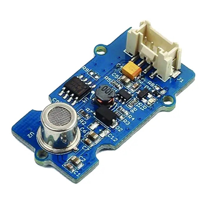
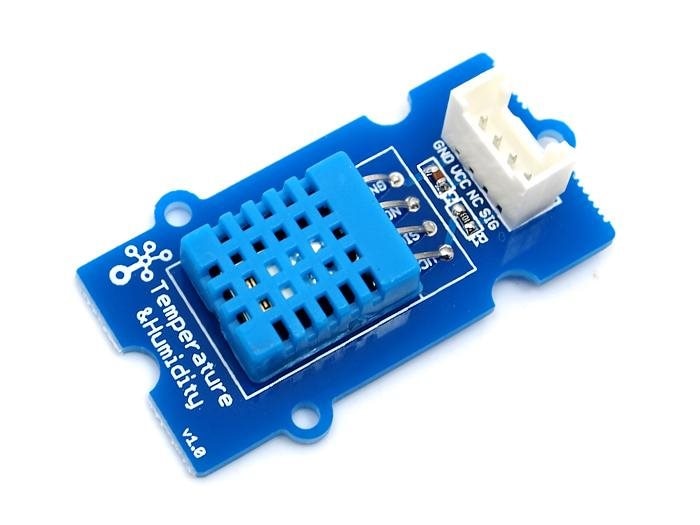
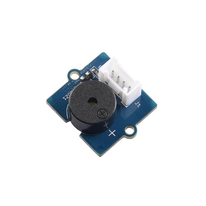
As environmental monitoring is very important for workers safety, I built a robot that will move around the warehouse and monitor the most important environmental parameters temperature, humidity and air quality. If any abnormality and uncomfortable situation found, it will instantly make an alert to aware all the workers nearby. The system will also upload the data to the cloud for real time remote monitoring and analysis. I used Blynk IoT Cloud for the cloud service. For temperature and humidity monitoring I used Grove DHT11 sensor and for air quality monitoring I used Grove air quality sensor. Arduino MKR WiFi is used for reading the sensors and uploading the data to cloud. For generating the alert Grove buzzer is used.
| {gallery}Hardware Components |
|---|
|
IMAGE TITLE: THEN IMAGE DESCRIPTION |
|
IMAGE TITLE: THEN IMAGE DESCRIPTION |
|
IMAGE TITLE: THEN IMAGE DESCRIPTION |
|
IMAGE TITLE: THEN IMAGE DESCRIPTION |

Connecting Hardware (Sensor Unit)
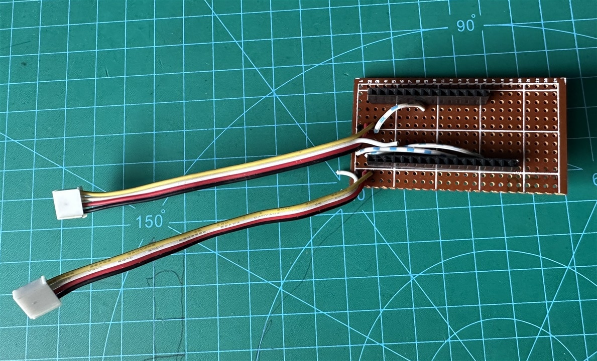
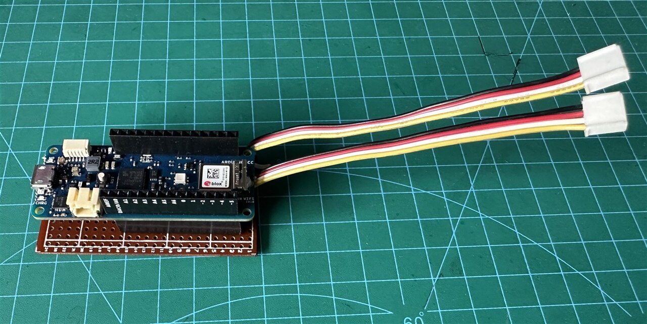
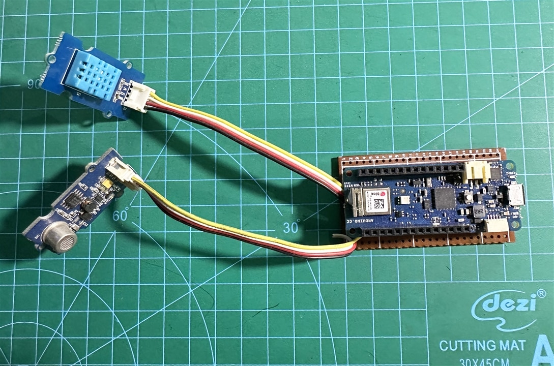
The Arduino MKR WiFi 1010 board comes with male pins on bottom side and female header on top. It makes it easy to connect external sensors with both female and male herders. The board also has a Qwiic connector but no Grove connector. For my warehouse worker safety project I need to connect a grove DHT11 temperature and humidity sensor and a grove air quality sensor. As the board has no grove connector and I don't have any grove shield for the MKR board, I prepared a PCB using a piece of perf-board.
I cut a Grove cable in the middle and solder both pieces into the PCB board so that I can connect two sensors. DHT11 sensor needs a digital pin and air quality sensor need an analog pin to communicate with Arduino.
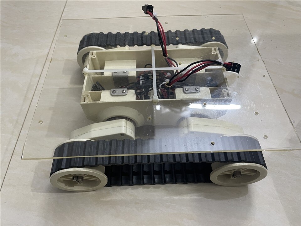
The Robot Base
The robot base will carry the sensor unit and move around the warehouse for monitoring and collecting sensor data. Building hardware is hard and more than hard for building robots where you have to work with lots of motors and sensors. When you have several medium or high-power motors in your project, providing the required amount of power also appears as a real challenge. Even sometimes you will get unstable behavior from your robot for not choosing the right size/type of wire. Making a bot from scratch involves lots of soldering and wiring works. Choosing a ready-made chassis can help to save a plenty amount of time. As the total project contains many tasks and the deadline is approaching soon, I selected a DFRobot Rover 5 tank chassis for the robot base to reduce some unnecessary complexity. I attached an acrylic sheet on top of the chassis by using zip ties.
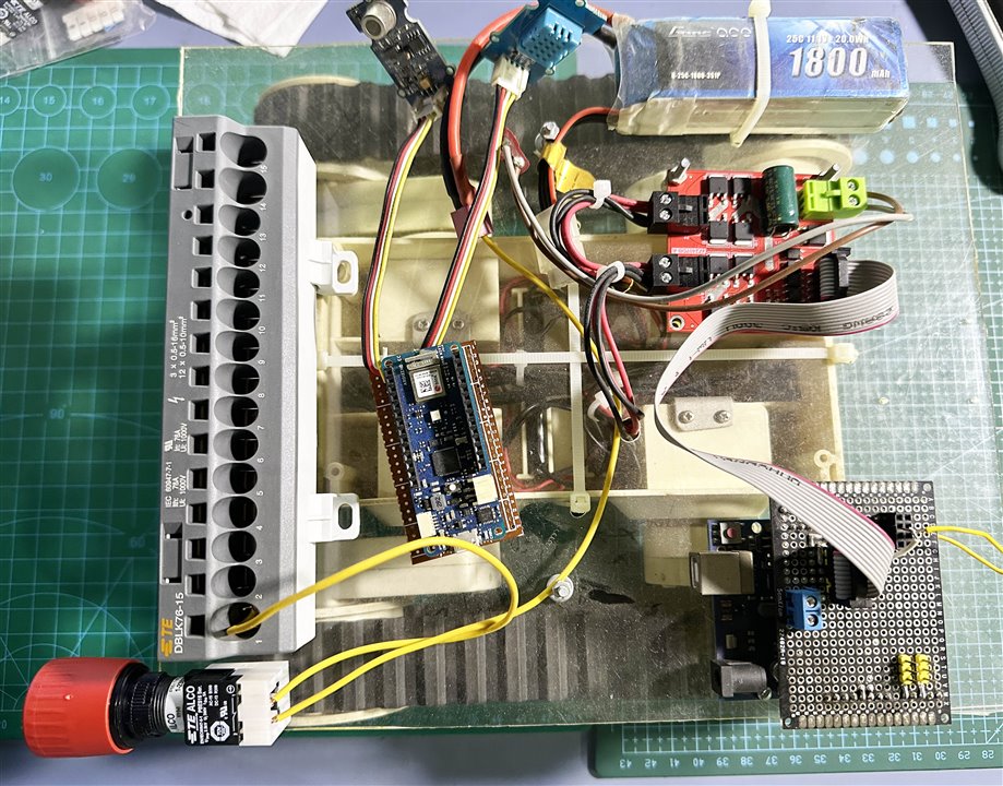
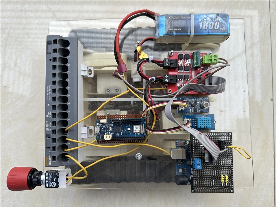
I used a Dual DC Motor Drive Module 7A 160W, 24V for driving the motors. Using some M3 screws and nuts I attached the motor driver board and Arduino board on top of the acrylic base as shown in the image below.
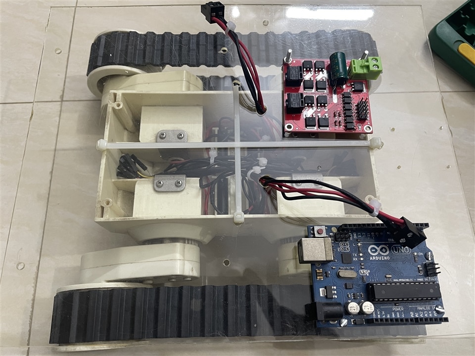
The motors are going to get power from a 3 cell lipo battery. I will also provide power to Arduino board from the lipo battery through VIN pin.
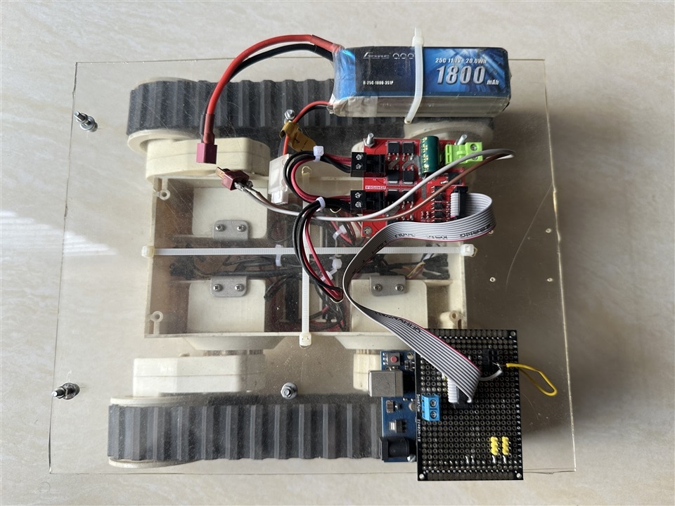
For making a stable connection from Arduino board to Motor Driver board I used a 10 pin jumper connector. I used a piece of PCB perf board to make like an Arduino shield and jumper is connected to the board using double line 10 pin male header.
The motor, motor driver and Arduino connections are shown in the following connection diagram:
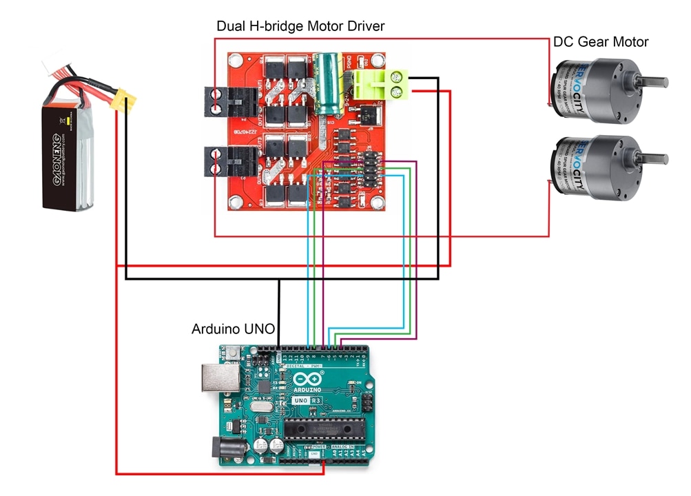
The following code for driving the robot base is used for testing purpose. The final robot will be based on the line following sensor and algorithm. Actually the robot will follow a track for moving and collecting sensor data.
#define LEFT_MOTOR_IN1 7
#define LEFT_MOTOR_IN2 8
#define RIGHT_MOTOR_IN1 4
#define RIGHT_MOTOR_IN2 5
#define LEFT_MOTOR_EN 9
#define RIGHT_MOTOR_EN 6


void setup() {
  // put your setup code here, to run once:
  Serial.begin(9600);

  pinMode(LEFT_MOTOR_IN1, OUTPUT);
  pinMode(LEFT_MOTOR_IN2, OUTPUT);
  pinMode(RIGHT_MOTOR_IN1, OUTPUT);
  pinMode(RIGHT_MOTOR_IN2, OUTPUT);
  pinMode(LEFT_MOTOR_EN, OUTPUT);
  pinMode(RIGHT_MOTOR_EN, OUTPUT);

}

void loop() {

  move_robot(100, 100); //move forward
  delay(5000);
  move_robot(100, -100); //turn right
  delay(1000);
  move_robot(100, 100); //move forward
  delay(5000);
  move_robot(-100, 100); //turn left
  delay(1000);
  move_robot(-100, -100); //move backword
  delay(5000);
}


void move_robot(int left_speed, int right_speed){
  int left_motor_speed = abs(left_speed);
  int right_motor_speed = abs(right_speed);
  analogWrite(LEFT_MOTOR_EN, left_motor_speed);
  analogWrite(RIGHT_MOTOR_EN, right_motor_speed);
  if(left_speed>=0){
    digitalWrite(LEFT_MOTOR_IN1, HIGH);
    digitalWrite(LEFT_MOTOR_IN2, LOW);
  }
  else if(left_speed<0){
    digitalWrite(LEFT_MOTOR_IN1, LOW);
    digitalWrite(LEFT_MOTOR_IN2, HIGH);
  }
  if(right_speed>=0){
    digitalWrite(RIGHT_MOTOR_IN1, HIGH);
    digitalWrite(RIGHT_MOTOR_IN2, LOW);
  }
  else if(right_speed<0){
    digitalWrite(RIGHT_MOTOR_IN1, LOW);
    digitalWrite(RIGHT_MOTOR_IN2, HIGH);
  }
}
A quick test of the robot base is shown in the video below:
Integrating Blynk to Arduino MKR WiFi 1010
One of the features of the sensor unit is to upload the sensor data to cloud for remote monitoring and analysis. As the main unit of the sensor part is a Arduino MKR WiFi, a wifi enable board, it can be easily done without connecting any separate communication module.
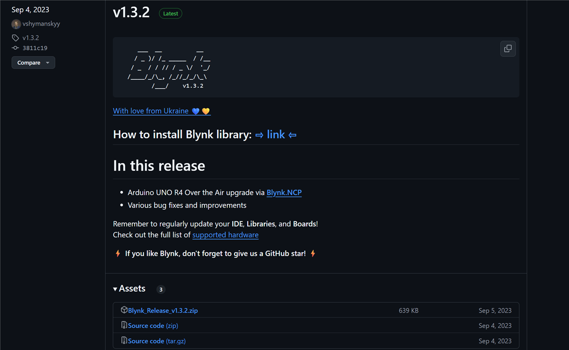
For integrating the Blynk cloud to the Arduino MKR WiFi 1010 board I downloaded the latest release of the Blynk library from the link: https://github.com/blynkkk/blynk-library/releases.
I created a template and made a dashboard on Blynk cloud platform for visualizing the sensors data. I included temperature, humidity and air quality reading in the dashboard shown in the screenshot below.

Then for programming I started with the example program for Arduino MKR 1010 board that was included in the Blynk library. I made all the necessary modification in the code and uploaded the code to the Arduino MKR board.
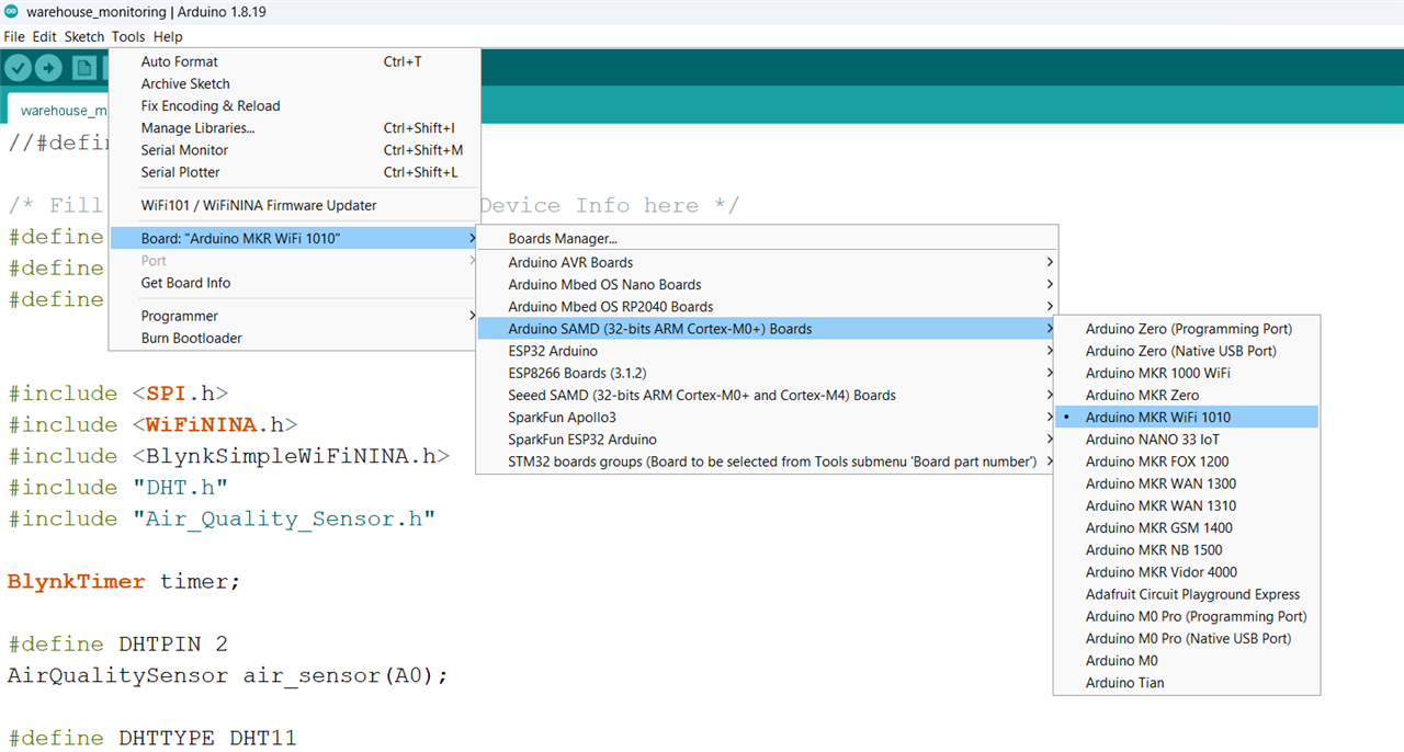
This kept this part totally independent from the robot controller unit. For robot controlling a separate Arduino is used. Both Arduino used independent code. Following is the code for sensor unit that was uploaded t the Arduino MKR WiFi 1010.
//#define BLYNK_PRINT Serial

/* Fill in information from Blynk Device Info here */
#define BLYNK_TEMPLATE_ID "TMPL6ZkZE1Xre"
#define BLYNK_TEMPLATE_NAME "warehouse monitoring"
#define BLYNK_AUTH_TOKEN "use your auth token here"


#include <SPI.h>
#include <WiFiNINA.h>
#include <BlynkSimpleWiFiNINA.h>
#include "DHT.h"
#include "Air_Quality_Sensor.h"

BlynkTimer timer;

#define DHTPIN 2
AirQualitySensor air_sensor(A0);

#define DHTTYPE DHT11
DHT dht(DHTPIN, DHTTYPE);

// Your WiFi credentials.
// Set password to "" for open networks.
char ssid[] = "*************"; //put your wifi name
char pass[] = "*************"; //put your wifi password

float temperature, humidity;
String air_quality = "";

void send_to_blynk()
{
  read_temp_humidity(); //read temperature & humidity
  read_air();           //read air quality
  Blynk.virtualWrite(V0, temperature);
  Blynk.virtualWrite(V1, humidity);
  Blynk.virtualWrite(V2, air_quality);
}

void setup()
{
  // Debug console
  Serial.begin(9600);

  Blynk.begin(BLYNK_AUTH_TOKEN, ssid, pass);
  // You can also specify server:
  //Blynk.begin(BLYNK_AUTH_TOKEN, ssid, pass, "blynk.cloud", 80);
  //Blynk.begin(BLYNK_AUTH_TOKEN, ssid, pass, IPAddress(192,168,1,100), 8080);
  dht.begin();
  air_sensor.init();
  timer.setInterval(3000L, send_to_blynk); //call in every three seconds
}

void read_temp_humidity(){
  temperature = dht.readHumidity();
  // Read temperature as Celsius (the default)
  humidity = dht.readTemperature();
}

void read_air(){
  int quality = air_sensor.slope();
  if (quality == AirQualitySensor::FORCE_SIGNAL) {
      air_quality = "High pollution!";
  } else if (quality == AirQualitySensor::HIGH_POLLUTION) {
      air_quality = "High pollution!";
  } else if (quality == AirQualitySensor::LOW_POLLUTION) {
      air_quality = "Low pollution!";
  } else if (quality == AirQualitySensor::FRESH_AIR) {
      air_quality = "Fresh air.";
  }
}

void loop()
{
  Blynk.run();
  timer.run();
}
The Complete Connection Diagram
Following image shows the connection among all the hardware components. The Arduino MKR board is responsible for only sensor data collection, making alert and uploading the data to the cloud. The moving base has nothing to do with it. On the other side, the motor driver board is connected with Arduino UNO. That board has no connection with the sensor unit. Two units are working independently.
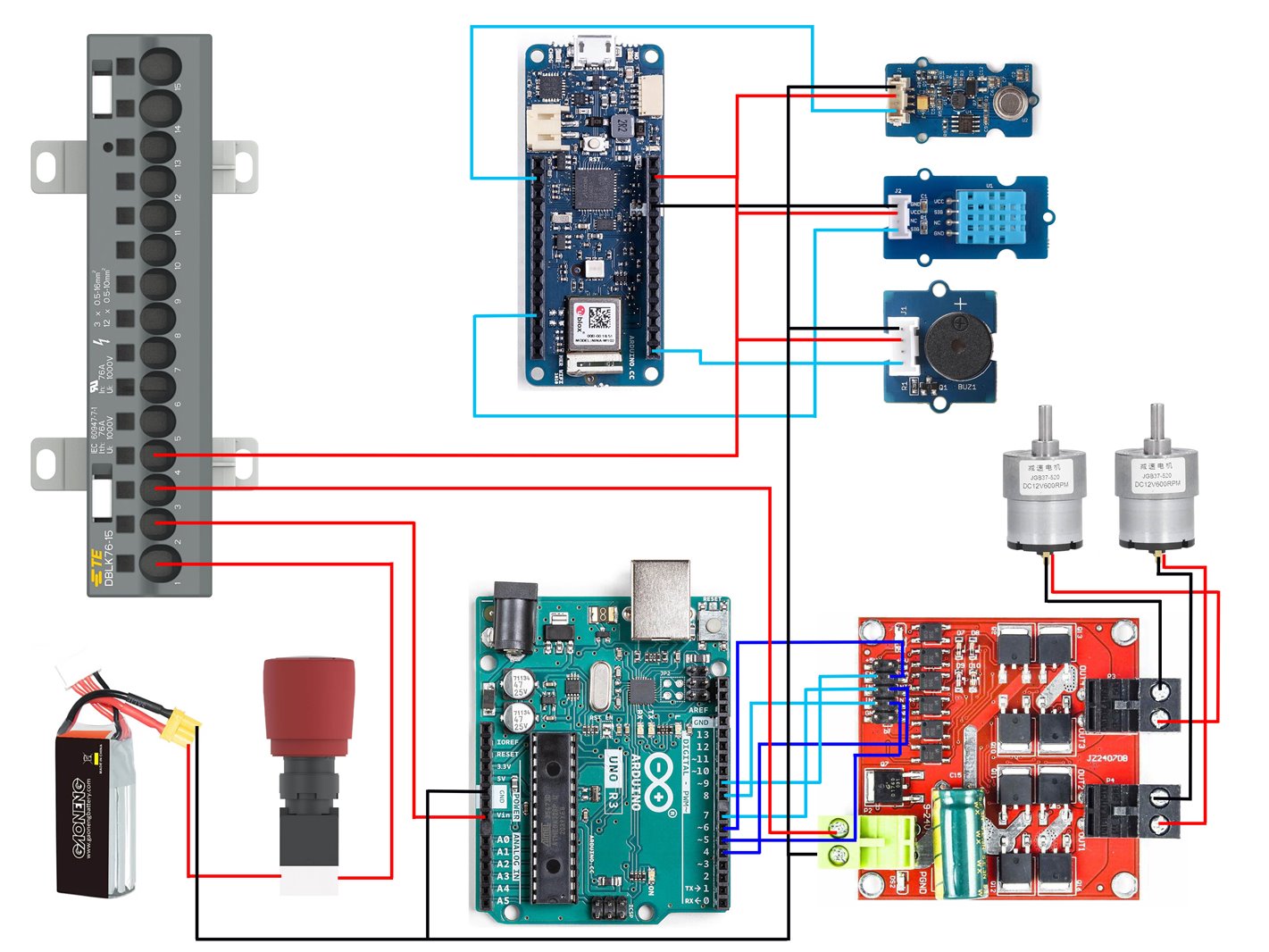
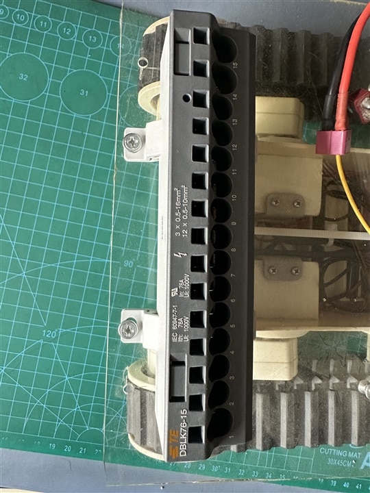
Distributing power to a complex project is not a easy task where lots of power connections is required. In my project I need to distribute 12V supply from the battery to different parts like motor driver board, microcontroller unit and the sensor unit. A power distribution block can be a good choice for this purpose. Here I am using the TE DBLK POWER DISTRIBUTION BLOCKS based on PI-Spring (Push-In & Spring) technology, specially designed for power distribution in control panel. No screw is required for this block and helps to save connection time.
The sponsor TE for this challenge provided DBLK76-15 power distribution block which is a high power 15 port distribution block, highly overrated for my project.
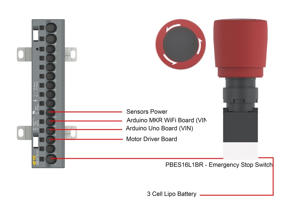
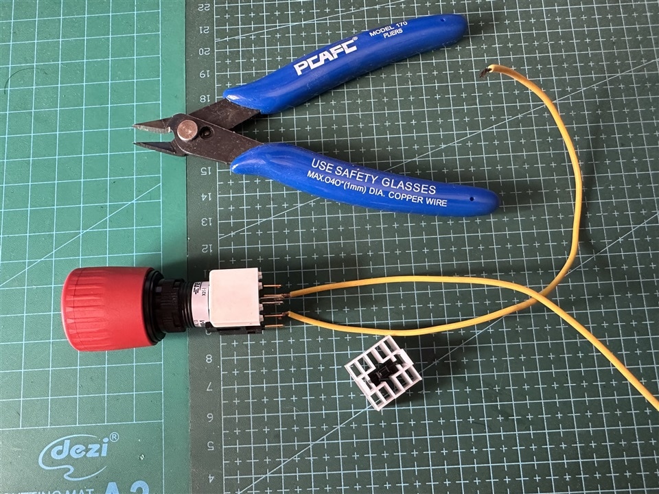
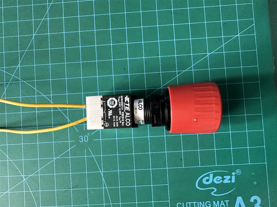
Above connection diagram shows the power connections among different components with the TE emergency switch. The following images show the connection of TE Emergency Stop switch.
Placement of the power distribution board and switch.
Connecting TE Power Terminal
I attached M3 nuts to attached the TE Power distribution terminal block with the robot base.
Then, I distributed the power to the motor driver board, and two Arduino boards. The power is in to the distribution block using TE Emergency switch.
Video in operation:
References
1. https://papers.ssrn.com/sol3/papers.cfm?abstract_id=4461490
3. https://www.itcon.org/papers/2014_4.content.05036.pdf
4. https://ecam.com/security-blog/are-you-following-these-warehouse-safety-protocols
5. https://safetyculture.com/topics/warehouse-safety/
6. https://immersivefactory.com/blog/311-Essential-Warehouse-Safety-Rules-to-Ensure-Employee-Protection
7. https://www.okaloneworker.com/resources/employee-safety-monitoring/