


Lorraine Underwood turns 60 glass bricks into a programmable RGB matrix using flexible addressable LEDs and a Raspberry Pi Pico 2 W. See how she tackles LED positioning, power, wiring and code to create animations, scrolling text and playable Tetris.
Building an Interactive Glass Brick RGB Display with a Raspberry Pi Pico 2 W
Lorraine Underwood has had around 60 glass bricks sitting in her garage for four years, waiting for a project. Rather than simply finding somewhere to use them as building materials, she had a rather more colourful idea: turn all 60 into individual pixels in a large interactive display for her front garden.
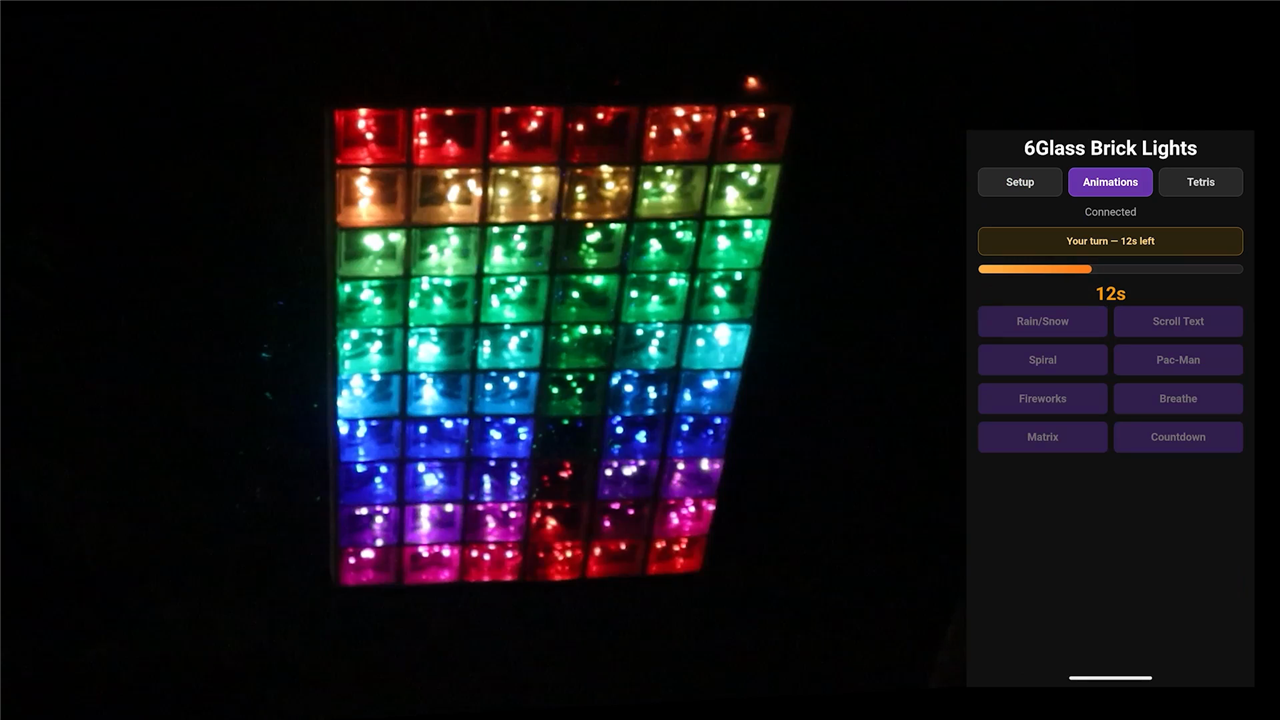
It is an idea that fits particularly well with Lorraine's previous projects. Addressable RGB LEDs have featured heavily in her work, including her interactive light-up window, where neighbours could alter the display from outside her house. This project takes the concept further by turning an arrangement of physical glass blocks into a 10 × 6 display that can show colours, patterns, animations, scrolling text and even play Tetris.
There wasn't a completely predetermined design to begin with. Instead, Lorraine worked through what the bricks, LEDs and their location would actually allow, starting with experiments in the garden before committing to the electronics or the frame.
“I don't have a plan. I have a shopping list, so you're kind of just going to follow along and let's see what we create.”
That experimental approach proved useful because several apparently small details, including where the LEDs sat against the glass, how clean the glass was and how the LEDs were arranged underneath each brick, made a surprisingly large difference to the finished display.
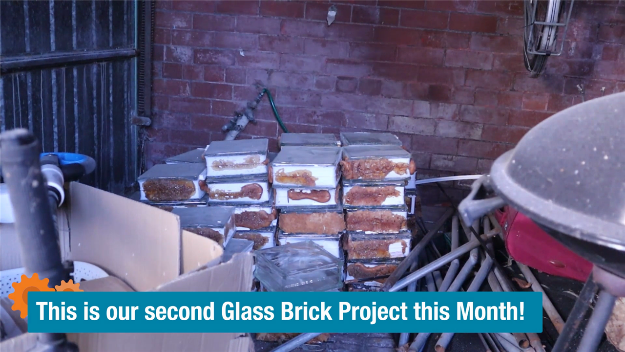
Turning Glass Bricks into Pixels
The display was intended to sit at the edge of Lorraine's front garden where it could be seen from the path. Six bricks across and ten high provided the obvious arrangement for the 60 available bricks, producing a coarse but useful 10 × 6 pixel matrix.
The first question was whether illuminating the blocks would actually work from the viewing angle available to somebody outside the garden. Lorraine initially experimented with a short NeoPixel strip connected to a micro:bit, lining up a few LEDs beneath several bricks.
Illuminating the brick from its edge worked much better than simply positioning a flat strip behind it. The textured and translucent glass spreads the light through the block, turning the whole brick into a glowing pixel rather than leaving the viewer looking directly at an obvious point source.
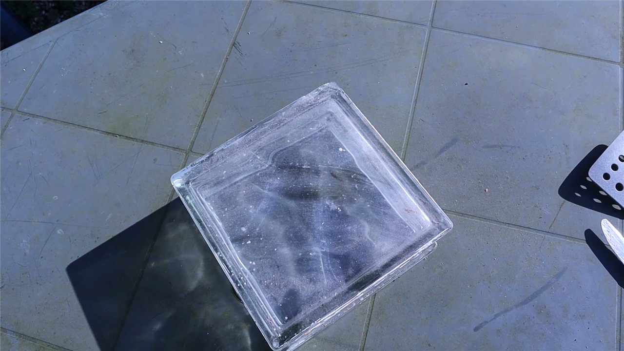
The experiments also revealed something rather less convenient: the condition of the bricks affected the light considerably.
“It was a dirty brick. Oops, so I'm going to have to clean them all.”
A clean block was visibly brighter than one carrying several years of dirt from storage. With 60 blocks to prepare, cleaning became a genuine part of creating a consistent display rather than simply a cosmetic exercise.
There was also the problem of light bleeding from one brick into another. Although early tests showed relatively little sideways bleed, stacking illuminated bricks made some spill into adjacent blocks visible. Lorraine's solution was mechanical rather than electronic: construct a wooden grid around the bricks. As well as keeping a tall stack of glass aligned on uneven ground, each wooden divider helps isolate one illuminated block from its neighbours.
This is important when the display is being treated as a matrix. A colour wash can tolerate some diffusion between blocks, but recognisable characters, animation and Tetris pieces need the viewer to be able to distinguish one pixel from the next.
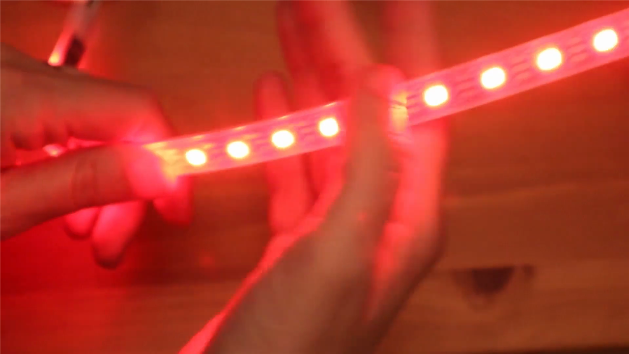
Choosing the RGB LEDs
A conventional addressable LED strip worked for the initial experiment, but it wasn't particularly well suited to six columns of large glass blocks. A PCB-based strip naturally wants to remain straight and its bending radius limits how it can be routed around the blocks.
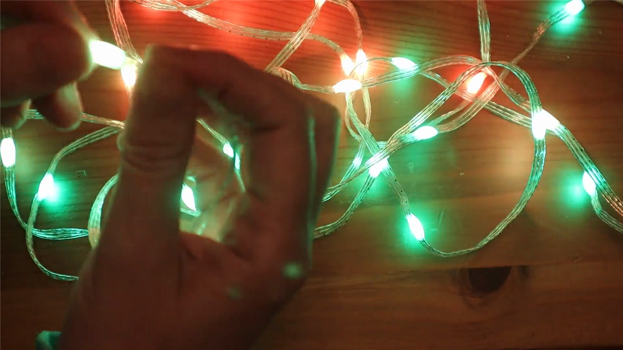
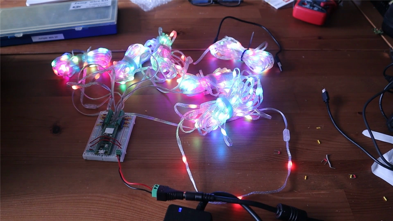
Lorraine instead tested Pimoroni's Addressable RGB LED Wire. The five-metre COM3214 wire contains 50 individually addressable WS2812B-4040 LEDs, spaced at ten LEDs per metre on thin three-core silver-coloured wire. The LEDs and solder joints are encapsulated in epoxy and the wire itself is rated IP67. Importantly for this build, it remains substantially more flexible than a conventional flat LED strip. The LEDs operate from 3.7 to 5.3 V, use RGB colour ordering and are rated at up to 0.24 W each at 5 V. The controller and connections still need their own protection outdoors, as the IP rating applies to the LED wire rather than automatically weatherproofing the rest of the electronics.
The flexibility meant individual groups of LEDs could be curled into position underneath the glass rather than forcing the physical construction to accommodate a rigid strip.
“You can arrange these as well. This feels more flexible than that strip because this strip won't bend nicely. Well, this is very bendable.”
Two LEDs behind each brick were tested first. They produced a recognisable illuminated block, but four LEDs gave a noticeably stronger and more even result. That established the final pixel design: each glass brick represents one logical pixel but is illuminated by four physical RGB LEDs.
The software therefore describes the installation as a grid of 10 rows, six columns and four LEDs per brick:
GRID_ROWS = 10
GRID_COLUMNS = 6
LEDS_PER_BRICK = 4
LED_START_OFFSET = 10
BRIGHTNESS = 1
Each physical strip contains 50 LEDs. Ten are skipped and the remaining 40 provide four LEDs for each of the ten bricks in that column. Six independently driven strips provide the six columns.
Driving Six LED Columns
The controller is a Raspberry Pi Pico 2 W. This gives the project an RP2350 microcontroller together with onboard 2.4 GHz Wi-Fi and Bluetooth 5.2 connectivity. The RP2350 runs at up to 150 MHz and provides 520 KB of on-chip SRAM. Wireless networking is particularly useful here because the Pico isn't simply generating animations locally; it also becomes the interface through which people can take control of the display.
Each LED column has its own GPIO connection:
STRIP_CONFIG = [
    ("GP15", 50),
    ("GP12", 50),
    ("GP9", 50),
    ("GP5", 50),
    ("GP3", 50),
    ("GP0", 50),
]
The implementation uses the RP2040/RP2350 family's Programmable I/O resources through Pimoroni's plasma.WS2812 support. A separate PIO state machine is assigned to each connected strip. With two PIO blocks containing four state machines each, the six physical LED columns fit comfortably within the available eight state machines.
There is another useful abstraction hidden in the software. What somebody sees as the leftmost column of the display isn't necessarily the first physical strip in the wiring. Rather than forcing the rest of the program to understand the installation's reversed wiring, a small function performs the conversion:
def physical_column(column):
    # The strips are wired up mirrored left-right versus the on-screen
    # grid, so column 0 on screen is actually the rightmost strip.
    return GRID_COLUMNS - 1 - column
This became particularly relevant when Lorraine first tried displaying scrolling text. “HELLO WORLD” initially wasn't especially recognisable because some columns were in the wrong order. Correcting the logical-to-physical mapping fixed the problem without requiring the entire display to be rewired.
“I also fixed the problem with Hello World. Some of my columns were in the wrong order, so you can see Hello World makes sense now.”
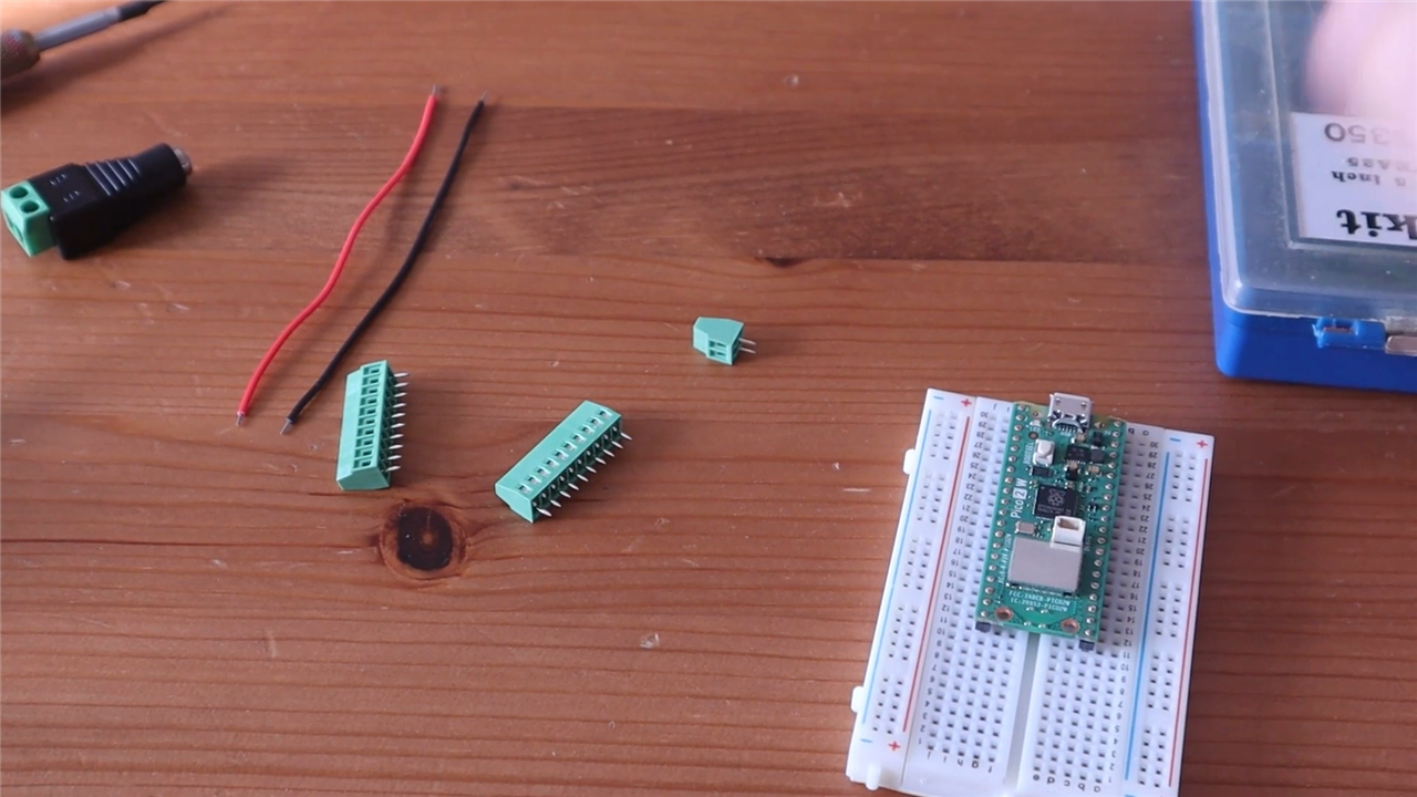
Power, Wiring and a Costly Mistake
A 60-pixel display becomes considerably larger electrically when every apparent pixel actually contains four LEDs. Lorraine therefore used a separate 5 V power supply rather than expecting the Pico's USB connection to run the completed installation.
The specified Mean Well GST60A05-P1J is a 30 W desktop supply providing 5 V at up to 6 A through a centre-positive 2.1 × 5.5 mm barrel connector. It also provides short-circuit, overload and over-voltage protection. Its 30 W rating should not be confused with the theoretical maximum consumption of every RGB LED at full output simultaneously, so both brightness and display content remain relevant when considering the final power budget.
For the prototype, each strip needed power, ground and its own data connection, initially brought together on a breadboard with screw terminals. It quickly became a fairly substantial collection of wires.
“Every light strip has ground, power and data. There'll be some deep digging to figure out which light strip is connected to which GPIO in the code before we can start playing Tetris.”
The breadboard stage also delivered the most expensive lesson in the build. While preparing an outdoor test Lorraine accidentally connected part of the circuit incorrectly and lost three LED strips.
“Sad news. I blew... I blew three strips. I think I put the board on wrong.”
One spare strip was available and another survived because its data lead had not actually been connected, leaving the project only one strip short. It is a good reminder that large addressable LED installations may still operate at only 5 V, but distributing power, ground and several data lines across hundreds of LEDs makes wiring discipline important. Checking polarity and continuity before applying power is considerably cheaper than discovering an error with several strips connected simultaneously.
Making Each Brick a Programmable Pixel
Once the physical arrangement had been established, the software could treat the installation as a conventional 60-pixel matrix. set_brick() is the central translation between those two worlds. A caller specifies a row, column and RGB colour, and the function calculates the four corresponding physical LEDs:
def set_brick(row, column, r, g, b):
    if not (0 <= row < GRID_ROWS and 0 <= column < GRID_COLUMNS):
        return False

    strip = strips[physical_column(column)]
    if strip is None:
        return False

    base = LED_START_OFFSET + (row * LEDS_PER_BRICK)

    for i in range(LEDS_PER_BRICK):
        strip.set_rgb(
            base + i,
            int(r * BRIGHTNESS),
            int(g * BRIGHTNESS),
            int(b * BRIGHTNESS)
        )
That makes the higher-level software considerably easier to understand. Animations do not need to know how four LEDs are curled underneath a brick or which GPIO drives them; they simply switch logical cells in the 10 × 6 grid on and off.
The result can do considerably more than illuminate the entire wall in one colour. The software includes rainbow and random-colour patterns, falling rain and snow, a spiral, fireworks, a breathing animation and green “matrix rain”. It even includes small sprite animations for Pac-Man and ghosts, along with a pumpkin animation.
Creating readable text on such a low-resolution display required a tiny purpose-built font. Characters are represented as arrays of strings in which 1 denotes an illuminated brick. The message is converted into a bitmap and moved a column at a time through the six-column viewport.
FONT_HEIGHT = 5

FONT = {
    "H": ["1001", "1001", "1111", "1001", "1001"],
    "I": ["111", "010", "010", "010", "111"],
    "L": ["1000", "1000", "1000", "1000", "1111"],
    "O": ["0110", "1001", "1001", "1001", "0110"],
}
With just ten rows and six columns, complex graphics have to be deliberately simple, but the large physical size of each “pixel” makes those small patterns surprisingly effective when viewed from the street.
Brightness Isn't Just a Software Number
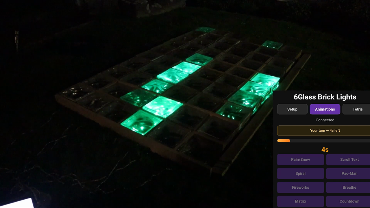
One of the more interesting visual effects only became obvious once all of the bricks were assembled. Some blocks appeared brighter than others even when their programmed RGB values were identical.
Initially this looked like an electrical or software brightness problem. Closer inspection suggested something simpler: the four flexible LEDs beneath every brick had not been positioned identically. Different positions changed how the light entered and diffused through the patterned glass.
“There's kind of no consistency in the layout of the LEDs... it just looks like it's the layout of the individual LEDs inside each brick.”
For anybody reproducing the project, consistently positioning the four LEDs beneath each block is therefore worth doing before the bricks are finally assembled. Software brightness correction could compensate for individual cells later, but getting the optical arrangement right first gives a much more predictable starting point.
Increasing the software brightness also made a substantial visual difference during the night-time testing. The display could even give an impressive result while the Pico was temporarily running from a laptop over USB, although the dedicated 5 V supply remains the appropriate choice for the completed installation.
Controlling the Display Over Wi-Fi
The Pico 2 W does more than drive the LEDs. It creates its own wireless access point named GlassBricks and hosts the control interface locally at 192.168.4.1.
SSID = "GlassBricks"
PASSWORD = "glassbricks"
IP = "192.168.4.1"
NETMASK = "255.255.255.0"
The accompanying index.html supplies the browser interface, while main.py implements the LED control, HTTP server and local DNS behaviour. The project is therefore self-contained: somebody standing outside does not need the display to be connected to Lorraine's household Wi-Fi or to a cloud service in order to interact with it.
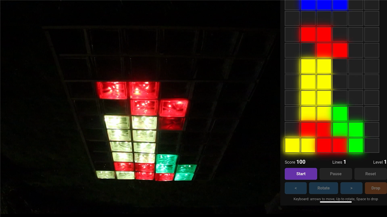
The HTTP interface provides endpoints for setting individual bricks, filling or clearing the matrix, applying random colours, producing a rainbow, reading the current state and launching animations. Tetris presents a slightly different challenge because an entire game frame may change rapidly.
Instead of issuing an HTTP request for every one of the 60 cells, the /gridset endpoint accepts the whole board in one update. It then compares each requested cell with the stored grid and skips LED writes for pixels that have not changed:
if current == "#" + hex_chunk or (
    current is None and hex_chunk == "000000"
):
    continue
This optimisation avoids repeatedly driving most of the display when only a falling Tetris piece has moved, helping the physical wall keep pace with the game running in the browser.
Letting the Neighbours Play Tetris
Allowing people outside the house to control the matrix introduces a problem that a private LED display doesn't have: what happens if several people try to use it simultaneously?
The software solves this with sessions and a timed turn lock. Once somebody starts interacting, that browser receives control of the display for 120 seconds. Other sessions can see that it is locked rather than fighting over the same LEDs. When the timer expires, the grid is cleared and control becomes available again.
TURN_SECONDS = 120
turn_lock_until = 0
turn_lock_owner = None
This is an improvement over the initial practical test, where 30 seconds simply wasn't long enough for a useful game of Tetris.
“The problem is I need more than 30 seconds to play a game of Tetris.”
When nobody is playing, the display doesn't have to sit empty. The firmware cycles through its idle animations, including rain, scrolling text, a spiral, Pac-Man, a pumpkin, fireworks, a breathing effect and Matrix-style falling green pixels, pausing between each effect.
An Outdoor Display Still Needs Outdoor Engineering and What Comes Next?
The first complete test was carried out on a clear night before all of the control electronics had been weatherproofed. That was fine for proving the idea, but not for a permanent installation.
“We haven't got anything waterproofed, like the controller, yet. But it's a clear night so far, so we think we'll be safe just for a quick demo before we waterproof everything.”
The LED wire itself is IP67 rated, but that does not extend the same protection to the Pico 2 W, breadboard, terminal blocks, barrel connector or exposed wiring. Lorraine's BOM therefore includes a waterproof enclosure alongside the glass bricks and timber frame. Any permanent version needs those electrical connections enclosed and protected from rain and damp, with suitable cable entry and strain relief rather than relying on the rating of the LED wire alone.
This also harks back to an earlier element14 Presents project where wet weather damaged the capacitive controls on Lorraine's interactive window. In the follow-up project she experimented with time-of-flight sensing and Raspberry Pi camera-based pose detection specifically to find more weather-resistant ways for neighbours to interact with an outdoor-facing installation.
The display works, but Lorraine doesn't consider connecting a phone to a Wi-Fi network and manually entering 192.168.4.1 to be the ideal experience for somebody who happens to walk past.
“At the moment we kind of have to get the neighbours to connect to the Wi-Fi Glass Bricks, and then they have to go to the website... We can have a QR code for both, like a QR to connect to the Wi-Fi and a QR to go to the website. But it's technically difficult for some people to do that.”
QR codes are one possible improvement, with one used to join the wireless network and another opening the controller. Lorraine is also considering returning to physical controls by placing weatherproof buttons near the wall, or revisiting the pose-detection idea from her previous project so the user themselves becomes the controller.
That last option could make the installation particularly entertaining: raise a left or right hand to move the falling Tetris piece, for example, without requiring a phone at all.
What began with 60 unused glass blocks has consequently become much more than an illuminated garden ornament. Each brick is now one enormous RGB pixel, four WS2812B LEDs provide its light, six independently controlled columns form a 10 × 6 matrix, and a Raspberry Pi Pico 2 W handles the display, games, animations and local wireless interface.
The imperfections discovered along the way are also useful parts of the build. Dirty glass really does reduce the apparent brightness. Flexible LEDs still need consistent positioning if every pixel isI’ve combined Lorraine’s build narrative, programming, BOM and the supporting element14 Community material into a fuller third-person article rather than simply turning the supplied description into a longer introduction. I’ve kept the practical failures and revisions because they are some of the most useful parts of the project, particularly LED placement, power, column mapping, outdoor protection and the interaction model. The BOM confirms the final build around a Raspberry Pi Pico 2 W, six-column LED arrangement, 5 V / 6 A supply and Pimoroni addressable RGB LED wire. Farnell identifies the Pico 2 W as an RP2350 board with 520 KB SRAM, 150 MHz operation and 2.4 GHz Wi-Fi, while CPC specifies the LED wire as 50 individually addressable WS2812B-4040 LEDs, 10 LEDs per metre, operating from 3.7 to 5.3 V and IP67-rated at the wire level.
After spending around four years sitting in Lorraine Underwood's garage, a collection of more than 60 glass bricks finally found a purpose. Rather than becoming part of a conventional wall, they would form an outdoor, individually addressable RGB display in the front garden, capable of showing colourful animations, scrolling messages and even playing Tetris.
There wasn't really a full design from the beginning. Lorraine started with bricks, some addressable LEDs and an idea of where the finished display might live, then tested each part of the concept before committing to the build. This made the project as much an exercise in experimentation as construction, with the arrangement of the LEDs, brightness, frame, wiring and software all developing in response to what actually worked outside.
Overall, it turned out to be a bright idea!
Resources and Related Projects
Parts Used
- Raspberry Pi Pico 2 W – RP2350-based wireless microcontroller controlling the display and hosting its local web interface.
- 6 × Pimoroni COM3214 addressable RGB LED wire – flexible 5 m wire containing 50 individually addressable WS2812B-4040 RGB LEDs.
- Mean Well GST60A05-P1J – 30 W, 5 V DC, 6 A external power supply.
- DC power connector – cable-mounted socket for the external supply.
- Multicomp Pro breadboard – used during wiring and development.
- Multicomp Pro 10-way and 2-way terminal blocks – used to distribute and terminate the LED wiring.
- 60 glass bricks – arranged as the physical 10 × 6 display.
- Wood – used to construct the supporting grid and separate the individual illuminated bricks.
- Waterproof enclosure – required to protect the controller and connections outdoors.
| Product Name | Manufacturer | Quantity | Buy Kit |
|---|---|---|---|
| Addressable RGB LED Wire, 5m - COM3214 | PIMORONI | 5 | Buy Now |
| Raspberry Pi Pico 2W | Raspberry Pi | 1 | Buy Now |
| MEAN WELL AC/DC Power Supply, ITE, 1 Output, 30 W, 5 VDC, 6 A | MEAN WELL | 1 | Buy Now |
| CLEVER LITTLE BOX DC Power Connector, Socket, Cable Mount, Screw | CLEVER LITTLE BOX | 1 | Buy Now |
| MULTICOMP PRO Breadboard, 8.5 mm Thickness, 55 mm x 83 mm | MULTICOMP PRO | 1 | Buy Now |
| MULTICOMP PRO Wire-To-Board Terminal Block, 2.54 mm, 10 Ways, 26 AWG, 18 AWG, 1 mm², Screw | MULTICOMP PRO | 4 | Buy Now |
| MULTICOMP PRO Wire-To-Board Terminal Block, 2.54 mm, 2 Ways, 26 AWG, 18 AWG, 1 mm², Screw | MULTICOMP PRO | 2 | Buy Now |
Additional Parts
| Product Name |
|---|
| Wood for the frame |
| Glass bricks |
| Waterproof box |