


Inductor Project: Battery Juicer
Learn how to get more bang from your battery by using an inductor to make a battery juicer that can run a flashlight off a single, used battery. |
 |  |

Bill of Material:
| Part | |||
|---|---|---|---|
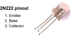
Bipolar (BJT) Single Transistor | Multicomp | 1 | Buy NowBuy Now |
Cylindrical Core Ferrite, 7.5 mm long, 19 mm ID, 29 mm OD | Fair-rite | 1 | Buy NowBuy Now |
| Prototype Board | Multicomp | 1 | Buy NowBuy Now |
| Slide Switch, SPDT, Through Hole | ALCOSWITCH - TE CONNECTIVITY | 1 | Buy NowBuy Now |
| Hook Up Wire, Black, 22 AWG, 25 ft, solid | NTE ELECTRONICS | 1 | Buy NowBuy Now |
| Hook Up Wire, Red, 22 AWG, 25 ft, solid | NTE ELECTRONICS | 1 | Buy NowBuy Now |
| 1K ohm resistor, 1/2W | NTE ELECTRONICS | 1 | Buy NowBuy Now |
| Battery Holder, AA x 1, Wire Leads | Keystone | 1 | Buy NowBuy Now |
Additional Parts:
| Product Name | Quantity |
|---|---|
Single LED Flashlight | 1 |
Top Comments