


Musical Emotions Emitter
Broadcasting Feelings Over Medium-Wave Radio
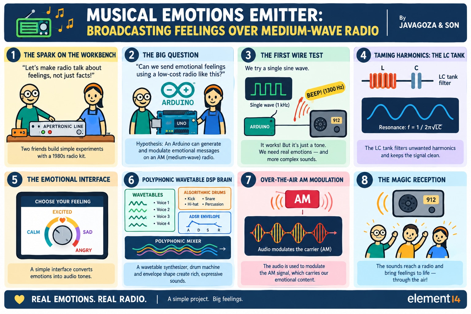
A 4-voice Arduino synthesizer, AM radio transmitter, and educational platform that transforms emotions into music and broadcasts them through the air.
 Try It Yourself
Don't feel like reading first? Experience the project right now. Listen to music from emotions, explore the synthesizer, and listen through a virtual AM radio receiver.

 Open-Source Resources
This article focuses on the design journey, experiments, and lessons learned. Readers interested in reproducing, studying, or extending the project can explore the companion repositories below.
 ️ Arduino Musical Emotions Emitter
Complete firmware, synthesizer engine, AM transmission system, hardware documentation, and implementation details.
Arduino Musical Emotions Emitter GitHub Repository
 Musical Emotions Emitter Emulator
Browser-based synthesizer, virtual AM receiver, DSP modules, user interface implementation, and development tools.
Emulator GitHub Repository
The repositories contain substantially more technical detail than can be included in a single article and provide a complete foundation for reproducing or extending the project.
Project abstract
The Musical Emotions Emitter is an Arduino UNO R4 Minima synthesizer and medium-wave AM transmitter. The user selects an emotion with a rotary encoder and OLED display; the system generates a short composition using polyphonic wavetable synthesis and algorithmic percussion, sends it to a local speaker, and uses it to modulate a medium-wave carrier. A browser-based emulator reproduces the main functions for experimentation and learning.
1. Introduction
What if a feeling could be turned into music and sent through the air as a radio signal?
This device explores this idea using an Arduino UNO R4 Minima, a software synthesizer, and a medium-wave transmitter. The result is a compact system capable of generating musical compositions and broadcasting them to a nearby AM receiver.
2. How the Project Started
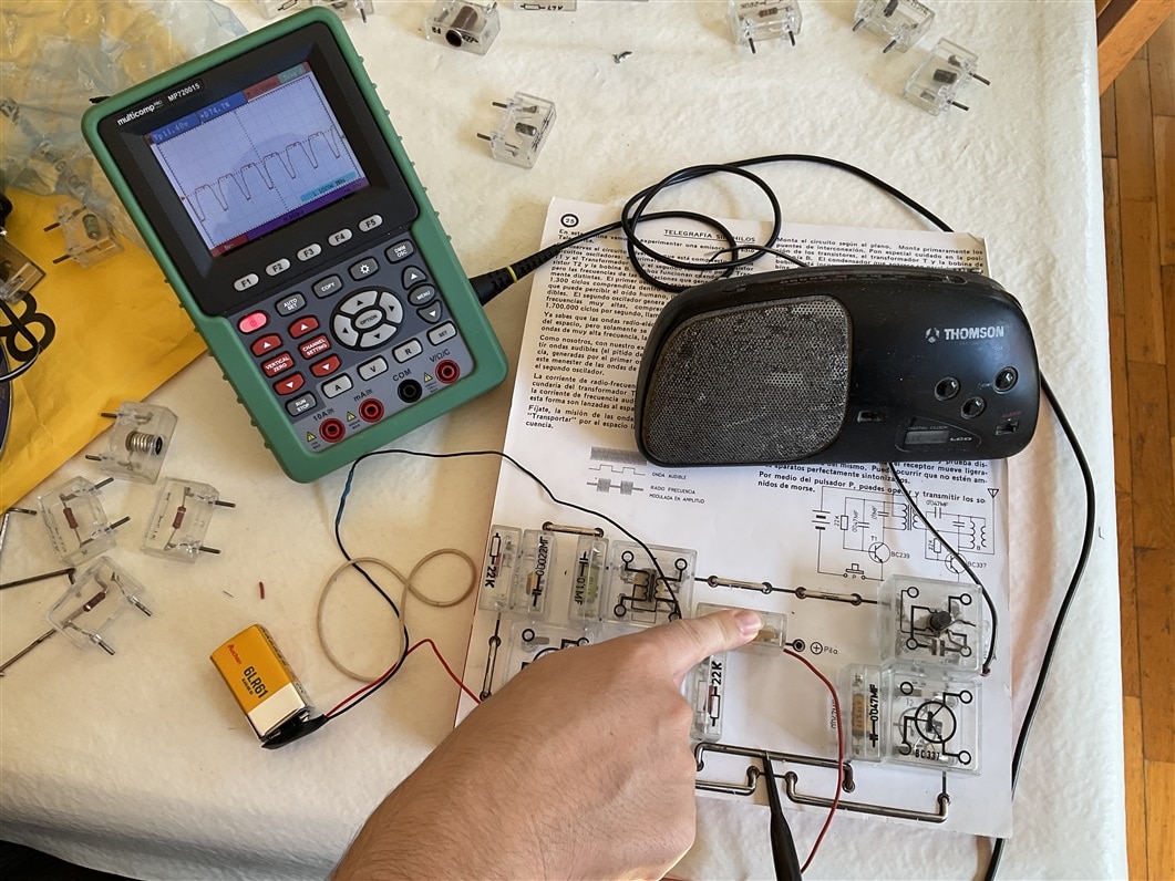
The project started with weekend electronics experiments with my son and an old AYPETRONIC educational kit. We built simple AM transmitters and receivers, tuned signals and used them to explore how information can travel through the air.
| AYPETRONIC electronics kit | First experiment with Arduino | Experiments with the resonant LC network, ferrite antenna, and AM receiver. |
|
|
 |
|
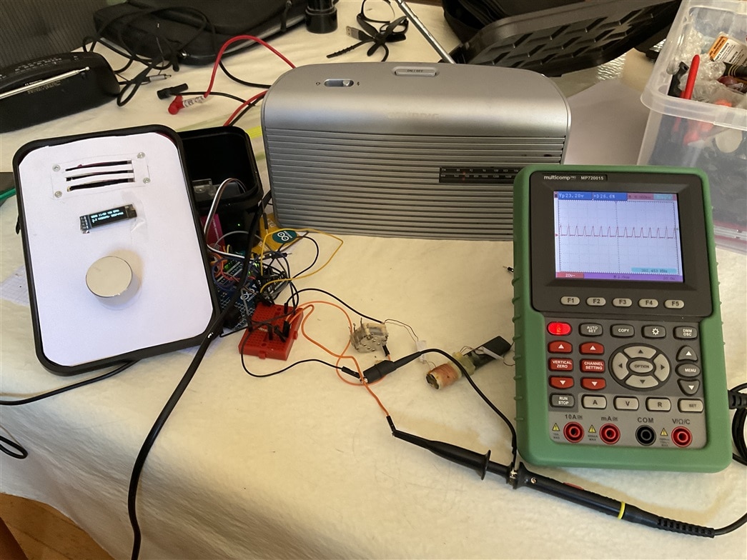
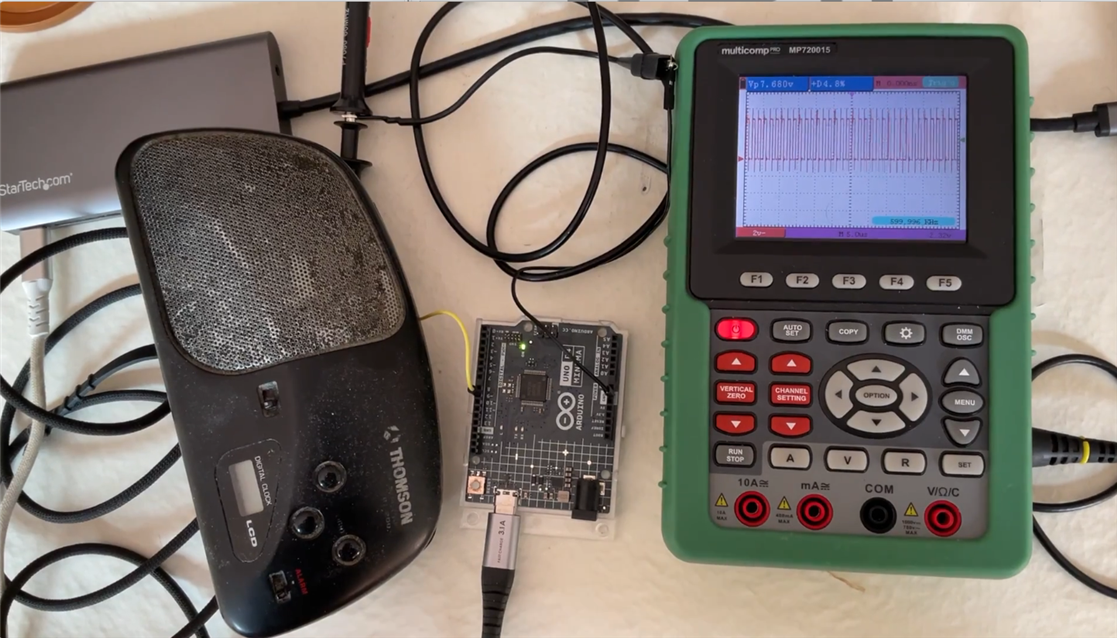
That led to a simple test: could the UNO R4 generate a medium-wave carrier directly? Using a hardware timer, we generated about 600 kHz and connected a short wire. A nearby AM radio detected it immediately. The signal was noisy and rich in harmonics, but it worked.
First experiment with the Arduino with PWM carrier signal at about 600 kHz.
That experiment led to the idea of transmitting something more useful than a test tone: music. The project then evolved into a small system in which different emotions are represented by different combinations of tempo, harmony, rhythm, timbre and effects. The technical challenge became as interesting as the musical one.
3. Finished System
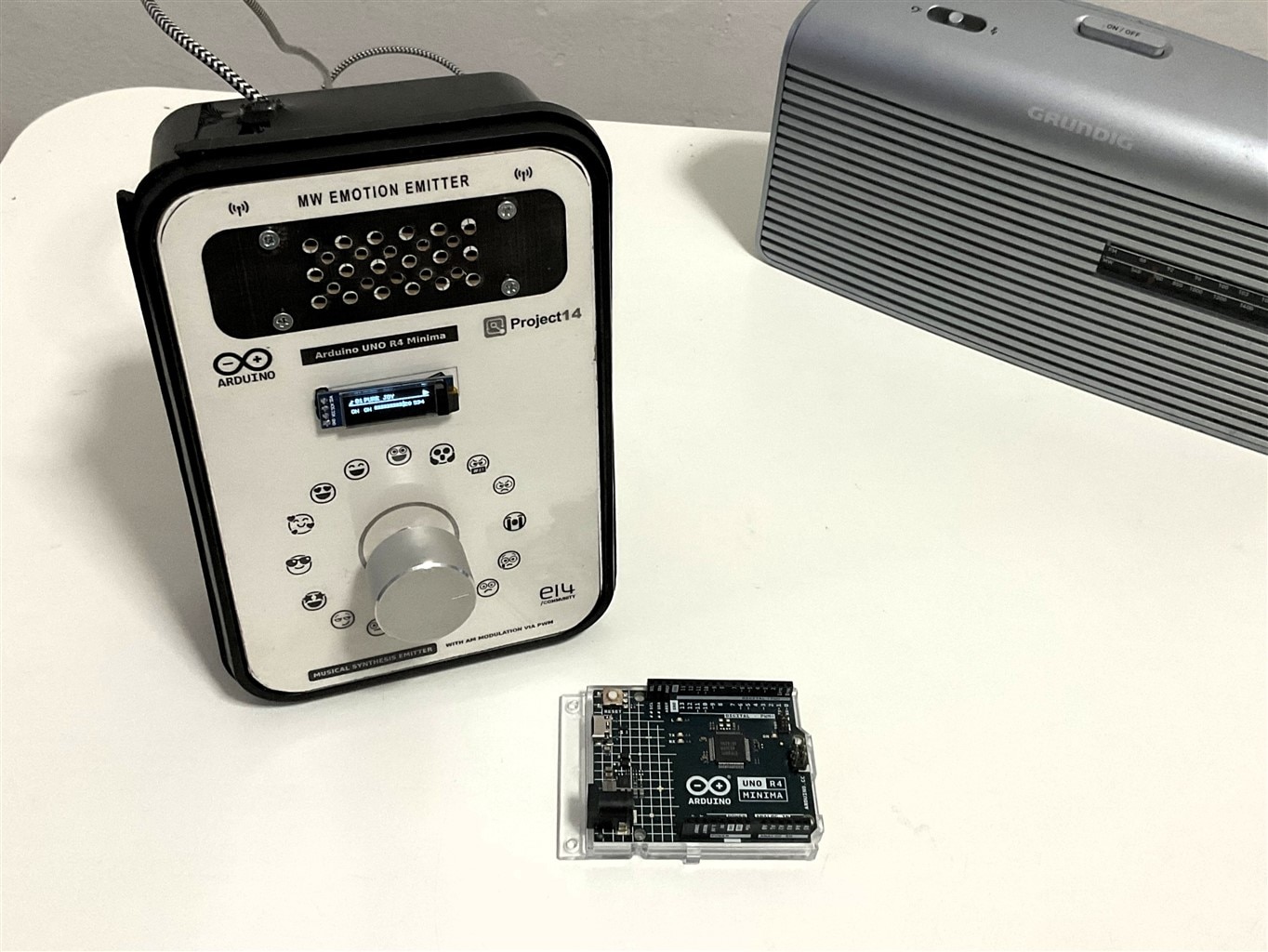
The finished prototype combines an Arduino UNO R4 Minima, OLED display, rotary encoder, loudspeaker and ferrite antenna. The Arduino handles the user interface, synthesis, DSP and carrier generation.
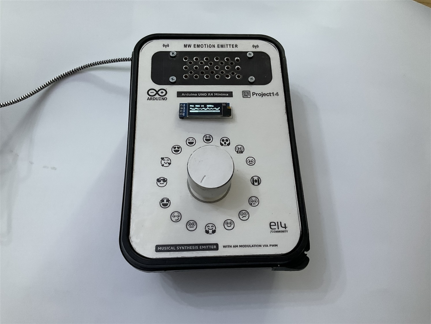
The completed Musical Emotions Emitter prototype.
Selecting a Composition
The encoder browses the library and its push button starts playback. The selected composition is synthesised as it plays; no prerecorded audio is stored.
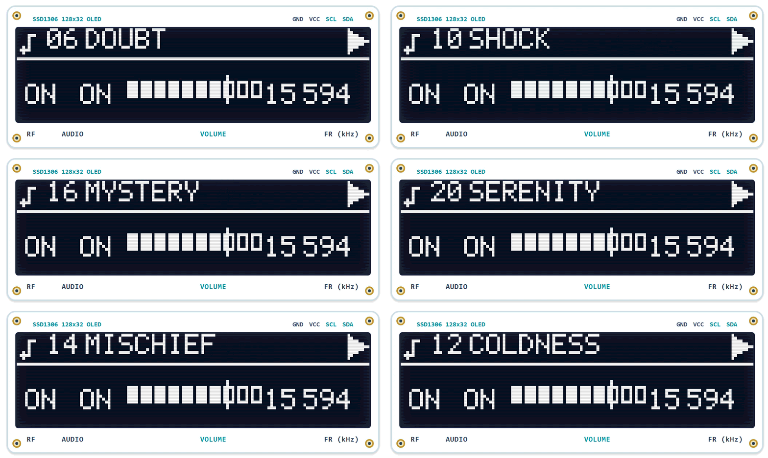
Browsing the available emotional states.
Emotion Playback and System Configuration
Broadcasting the Music Over the Air
The synthesized audio also controls the AM modulation. A nearby radio tuned to the transmitter frequency receives the same performance.
Selecting emotions, transmitting the generated music, and tuning a nearby AM radio receiver to hear the broadcast.
Playback Options
The same composition can be heard through the local speaker, a nearby AM receiver, or the web emulator.
| Monitor Playback | Audio Radio Reception | Web Emulator |
| Synthesized audio reproduced directly from the Arduino DAC output after delay-effect processing. | The same musical phrase received through a conventional AM radio receiver. | The same composition reproduced by the browser-based emulator. |
4. System Overview
The signal path is: composition → synthesis → DAC and AM modulation → RF driver → tuned ferrite antenna. The user interface controls the selection and playback.
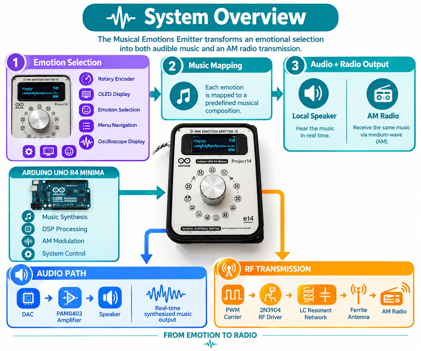
The main blocks are:
- User interface: rotary encoder and SSD1306 OLED.
- Composition Library: stored compositions interpreted by the sequencer.
- Digital audio synthesis: up to four melodic voices plus percussion.
- Radio transmission: PWM carrier, RF driver, tuned ferrite antenna and AM reception.
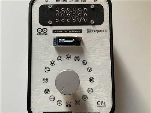
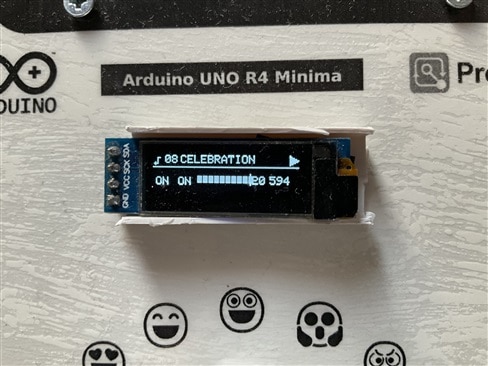
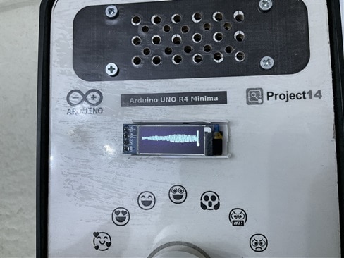
User interface featuring emotion selection, menu navigation, and real-time waveform visualization.
 |
 |
 |
Composition Library
Each emotion points to a short composition with its own tempo, harmony, rhythm, instrumentation and effects. The current version uses a curated library rather than generating music autonomously.
| Joy | Mystery |
Radio Transmission Chain
The synthesized audio modulates the Arduino-generated medium-wave carrier. A 2N3904 driver feeds the tuned ferrite antenna, allowing a nearby AM receiver to recover the music.
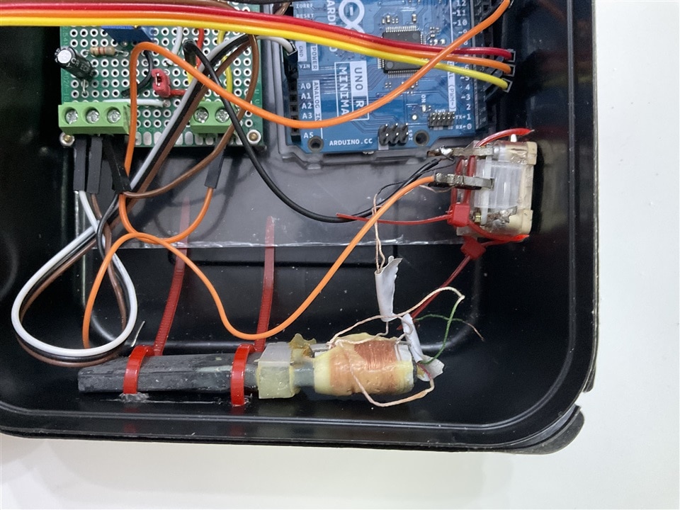
RF driver, ferrite antenna, and tuning capacitor.
5. Hardware Design
The hardware is simple: the UNO R4 Minima handles synthesis, signal processing, user interface and carrier generation; external circuitry provides audio amplification, RF driving and antenna tuning.
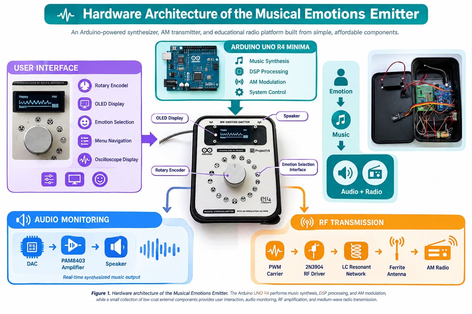
| Function | Main Components |
|---|---|
| Controller & DSP | Arduino UNO R4 Minima |
| User Interface | Rotary Encoder, SSD1306 OLED Display |
| Audio Monitoring | Arduino DAC, PAM8403 Amplifier, Loudspeaker |
| RF Transmission | 2N3904 Driver, Ferrite Rod Antenna, Polyvaricon Capacitor |
| Assembly & Power | Prototype Board, Passive Components, USB Supply |
5.1 Complete Schematic and Assembly
The schematic separates RF transmission, audio monitoring, user inputs and the OLED interface. This made each part easier to test before integration.
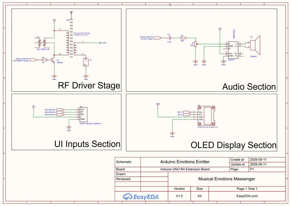
Complete schematic showing the RF driver, audio path, OLED and user inputs.
The RF section contains the transistor driver, ferrite antenna and tuning capacitor; the other sections provide audio output and control.
Protoboard Assembly
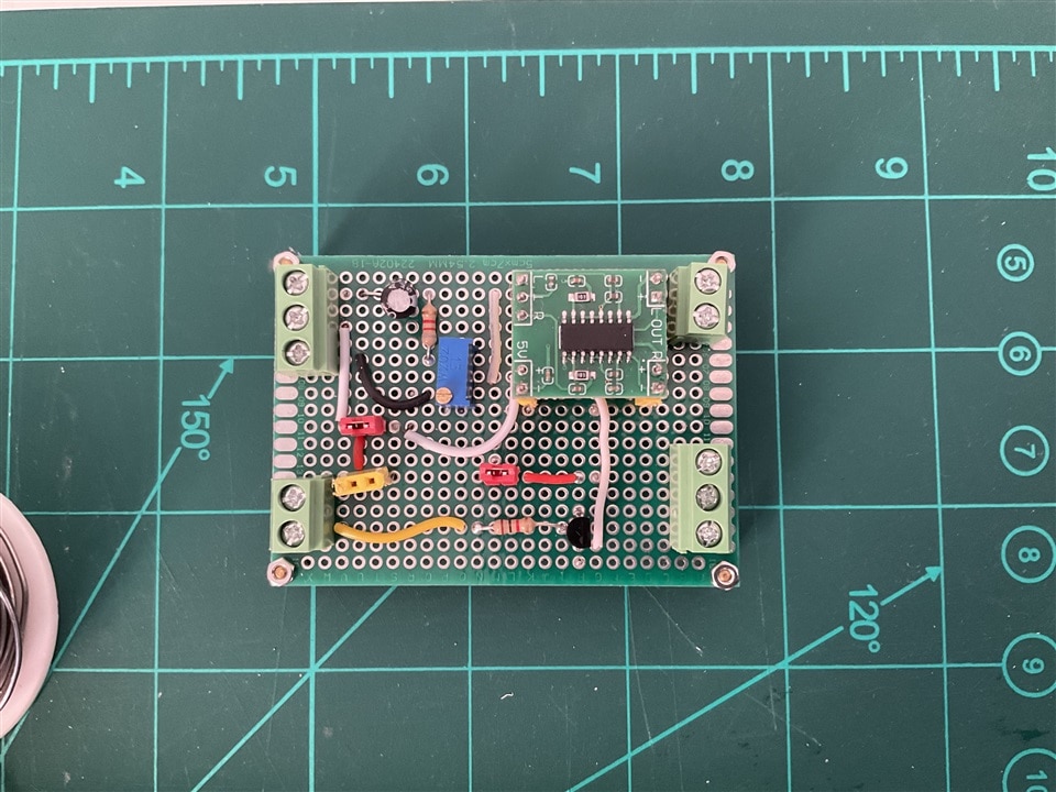
Most of the electronics were assembled on a small prototype board using through-hole parts and low-cost modules.
| Prototype board with the RF driver, PAM8403 interface and Arduino connections. | Internal view of the Musical Emotions Emitter. |
 |
 |
The antenna was kept away from the digital and audio circuitry to reduce coupling and interference.
5.2 Arduino UNO R4 Minima and User Interface
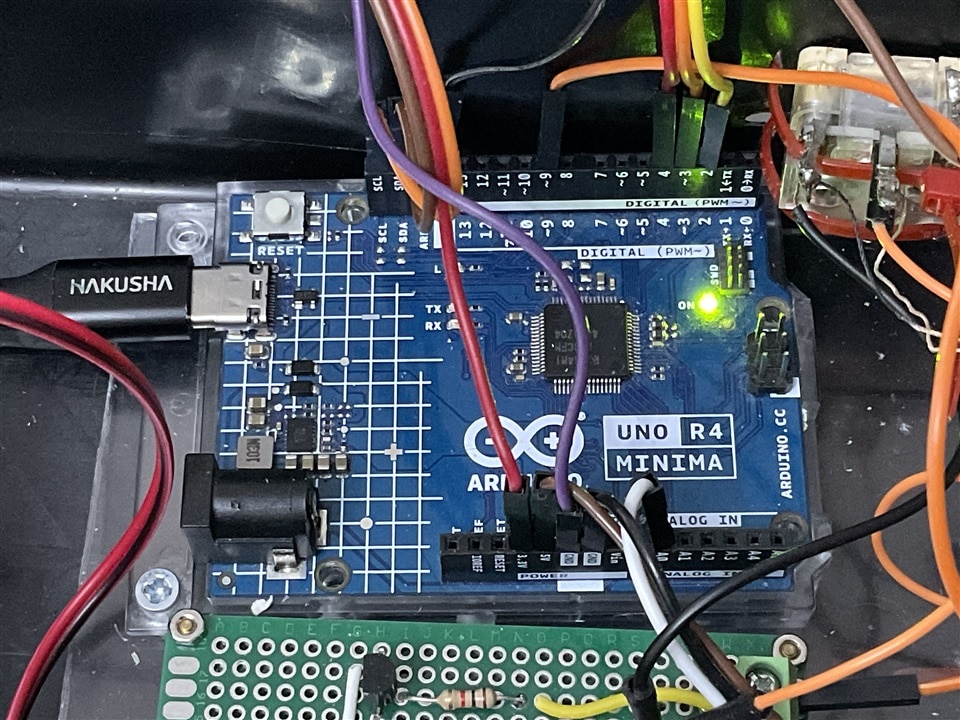
The UNO R4 Minima handles synthesis, modulation, display control and user input. Its integrated 12-bit DAC provides the analogue audio output.
| Arduino UNO R4 Minima | Arduino UNO R4 Minima Resource Usage |
 |
|
User Interface
The rotary encoder is the only input device. It selects emotions, songs and menus; the push button confirms selections. The OLED shows the selected emotion, playback status, transmission frequency, volume and a live waveform.
The same melody observed through the on-screen oscilloscope at different time-base settings.
5.2.1 Front Panel Design
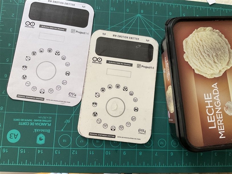
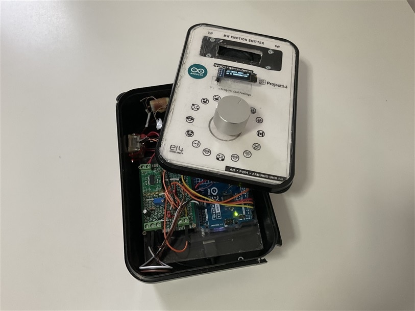
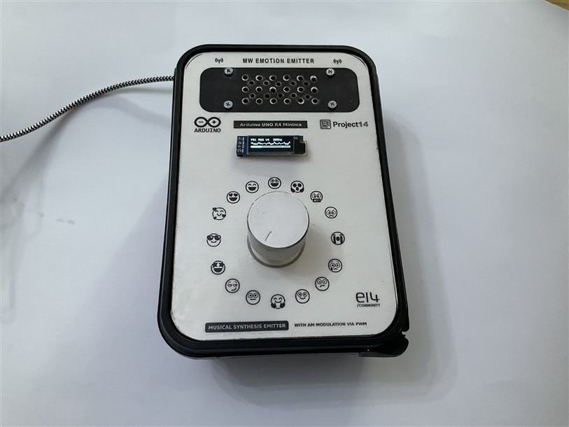
The front panel was first prototyped in foam board to check the layout. The final panel uses thin white-coated wood with the graphics printed in mirror image on transparency film and bonded with white glue, leaving the toner protected behind the film. Openings were cut with a Dremel.
|
Early foam-board prototype used to validate the layout and ergonomics of the user interface. |
Final front panel featuring the OLED display, rotary encoder, and emotion-selection graphics. |
Evolution from the foam-board prototype to the final wooden front panel with protected graphics. |
|
|
|
 |
5.3 Audio Monitoring
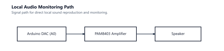
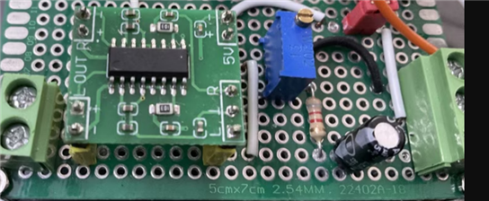
The UNO R4 DAC feeds a PAM8403 Class-D amplifier and a small loudspeaker. This path was useful for sound design, debugging and comparing the original audio with the AM-recovered signal.
| Local audio monitoring path. | PAM8403 amplifier board. Class-D audio amplifier used for local monitoring. |
 |
 |
5.4 RF Driver Stage
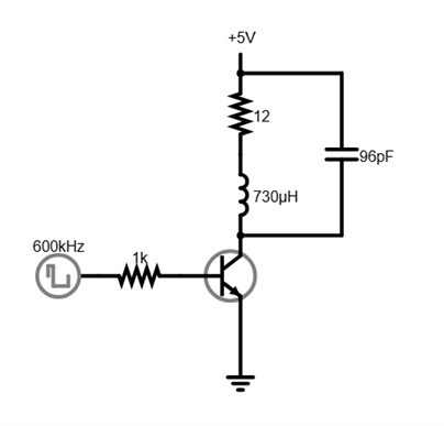
The carrier is generated by a hardware timer in PWM mode. A 2N3904 NPN transistor between the PWM output and tuned LC network acts as a switch, isolating the microcontroller and transferring energy into the resonant circuit.
| 2N3904 switching stage used to drive the resonant antenna network while isolating the Arduino output pin. | RF driver stage assembled on the prototype board. |
 |
|
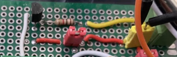
The tuned LC network selects the carrier and attenuates much of the PWM harmonic content. The ferrite antenna is both the inductive element and the means of coupling energy to nearby receivers.
5.5 Ferrite Antenna and Resonant Network
The first tests used a short wire directly from the Arduino. It produced a detectable signal but poor selectivity and strong harmonics. The final design uses a ferrite rod, coil winding and polyvaricon capacitor as a tuned LC network.
| Component | Function |
|---|---|
| Ferrite Rod | Magnetic antenna core |
| Coil Winding | Provides the inductance |
| Polyvaricon Capacitor | Tunes the resonant frequency |
The network selects the transmission frequency, reinforces the carrier, suppresses harmonics and improves coupling to nearby AM receivers. The ferrite rod and tuning capacitor were salvaged from discarded radios.
Characterizing the Ferrite Antenna
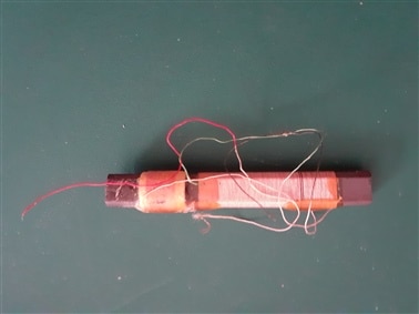 |
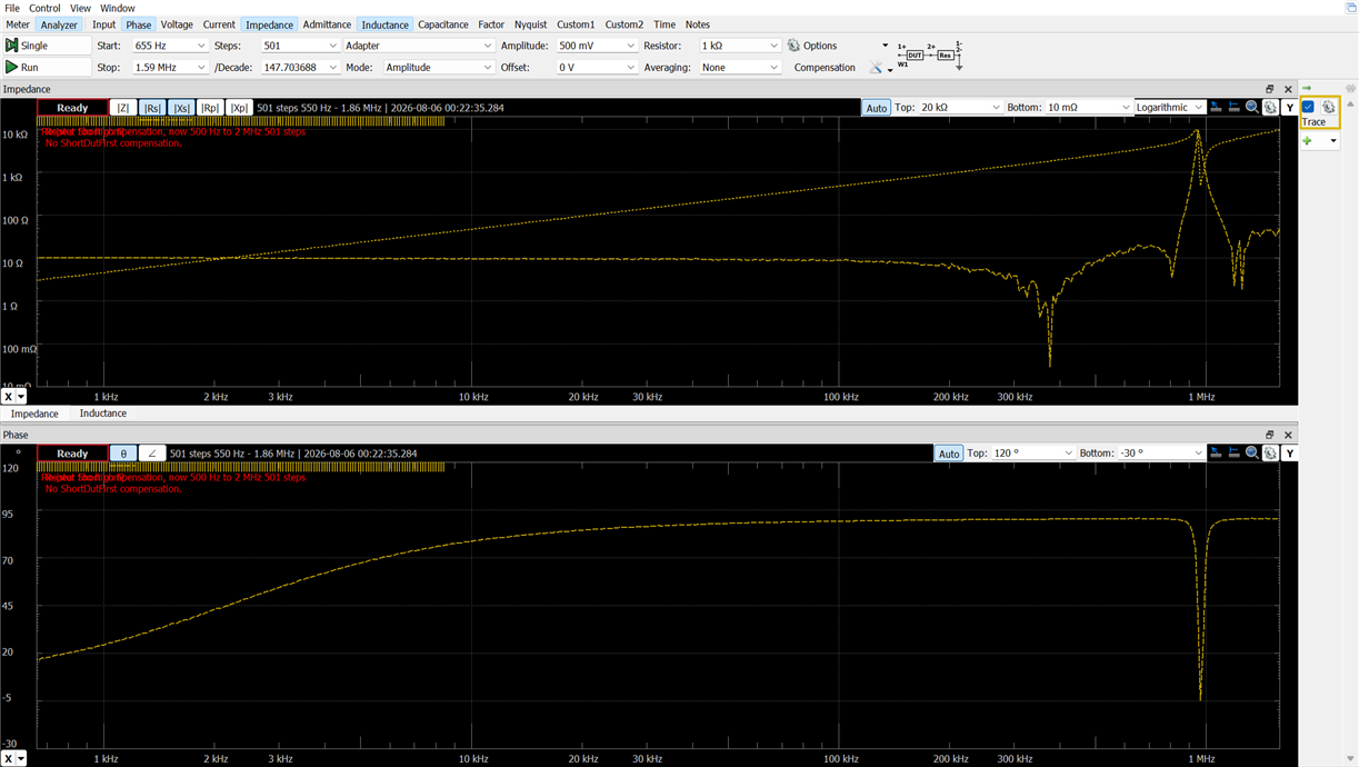
Several salvaged antennas were tested. Resistance measurements identified the windings and an Analog Discovery 2 was used for inductance measurements. |
| Impedance measurement of the 12 Ω winding. | ||||||||||
 |
|
Estimating the Tuning Capacitance
With ~730 µH and a target frequency near 600 kHz, the calculated resonant capacitance was about 96 pF, within the expected range of the salvaged polyvaricon.
| Parameter | Value |
|---|---|
| Inductance | ~730 µH |
| Carrier Frequency | ~600 kHz |
| Estimated Capacitance | ~96 pF |
Integration and Tuning
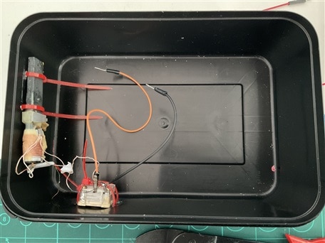
The antenna was mounted along one side of the enclosure, away from the loudspeaker and digital electronics, with the tuning capacitor accessible for adjustment. Small changes in capacitance produced clear changes in RF voltage and received signal strength.
 |
|
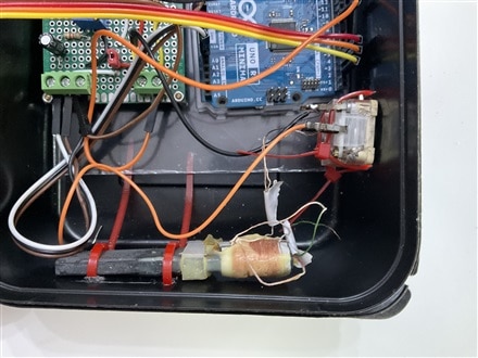
Ferrite antenna and polyvaricon capacitor installed in the completed system.
The tuned network increased the carrier amplitude and reduced harmonic content compared with the original wire-antenna setup.
Early resonant-network experiments.
The first ferrite antenna, tuning capacitor, Arduino transmitter, AM receiver, and oscilloscope assembled on the workbench during development.
5.6 Hardware Bill of Materials
| Qty | Component | Notes |
|---|---|---|
| 1 | Arduino UNO R4 Minima | Main controller, synthesizer, and AM transmitter |
| 1 | SSD1306 OLED Display | User interface and oscilloscope display |
| 1 | Rotary Encoder with Push Button | Navigation and control |
| 1 | PAM8403 Audio Amplifier | Local audio monitoring |
| 1 | Loudspeaker | Audio output |
| 1 | 2N3904 NPN Transistor | RF driver stage |
| 1 | Ferrite Antenna | Salvaged from a discarded radio |
| 1 | Polyvaricon Capacitor | Salvaged tuning capacitor |
| Assorted | Resistors and Capacitors | RF, audio, and interface circuitry |
| 1 | Prototype Board | Circuit assembly |
| 1 | USB Power Supply | System power |
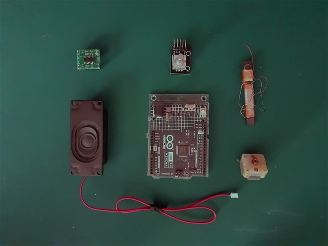
Major components required to build the Musical Emotions Emitter.
6. The Musical Emotions Engine
6.1 Emotional Profiles and AI-Assisted Creation
Each entry is a short composition, not a scientific model of emotion. Tempo, harmony, rhythm, timbre, instrumentation and effects are used to give each selection a distinct character.
| Emotion | Musical Characteristics |
|---|---|
| Joy | Bright harmonies, energetic rhythms |
| Calm | Slow tempos, sustained chords |
| Mystery | Sparse melodies and ambient textures |
| Confidence | Strong rhythmic patterns and brass-like timbres |
| Sadness | Minor tonalities and descending phrases |
| Wonder | Bell-like textures and ascending arpeggios |
| Excitement | Fast tempos and dynamic percussion |
Tune expressing Doubt:
LLMs were used as creative assistants when developing the compositions. For each emotion, they suggested possible tempo, harmony, instrumentation, rhythm, polyphony, effects and ending style. The suggestions were then reviewed, changed and converted into the synthesizer's song format; they were not used as finished songs.
From AI-prompt to musical composition:
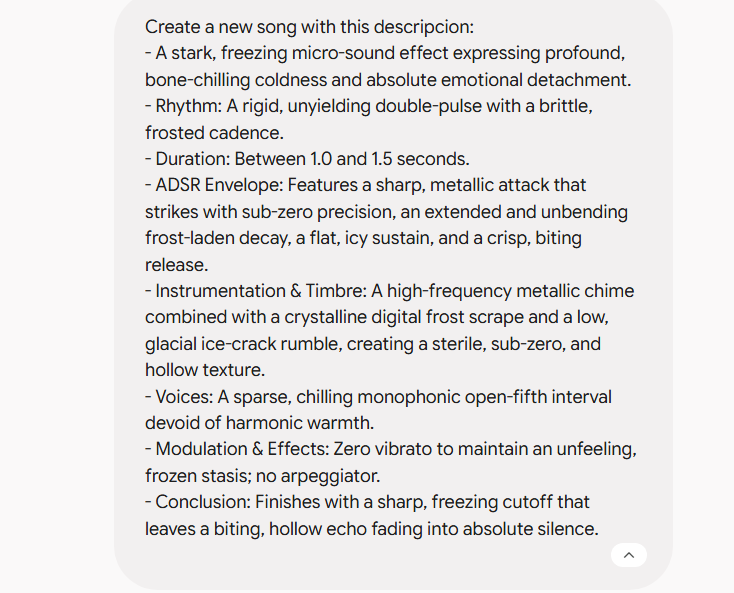 |
Example emotional prompt and resulting synthesized composition.
6.2 Representing Music in Memory
Music is stored as compact instructions rather than audio: each voice contains notes, rhythm and an instrument, which the synthesizer turns into sound during playback.
Internal song representation used by the synthesizer.
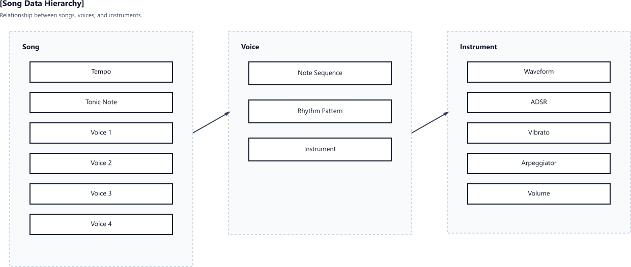
The current implementation supports up to four simultaneous melodic voices plus a dedicated percussion track. This keeps the musical data small while allowing reasonably rich arrangements.
| Tubular bells | Harpsicord |
|
|
|
6.3 Future Music Generation
The current system uses a fixed library. A future version could generate melodies, harmony, rhythms and arrangements dynamically while keeping the selected emotional profile. That would make each performance different without changing the synthesis engine.
7. Software Architecture
7.1 Synthesis, Sequencing and Audio Delivery
The sequencer reads the selected composition and schedules notes and percussion. The synthesis engine generates the voices and effects; the resulting audio stream feeds both the DAC and AM modulation stage.
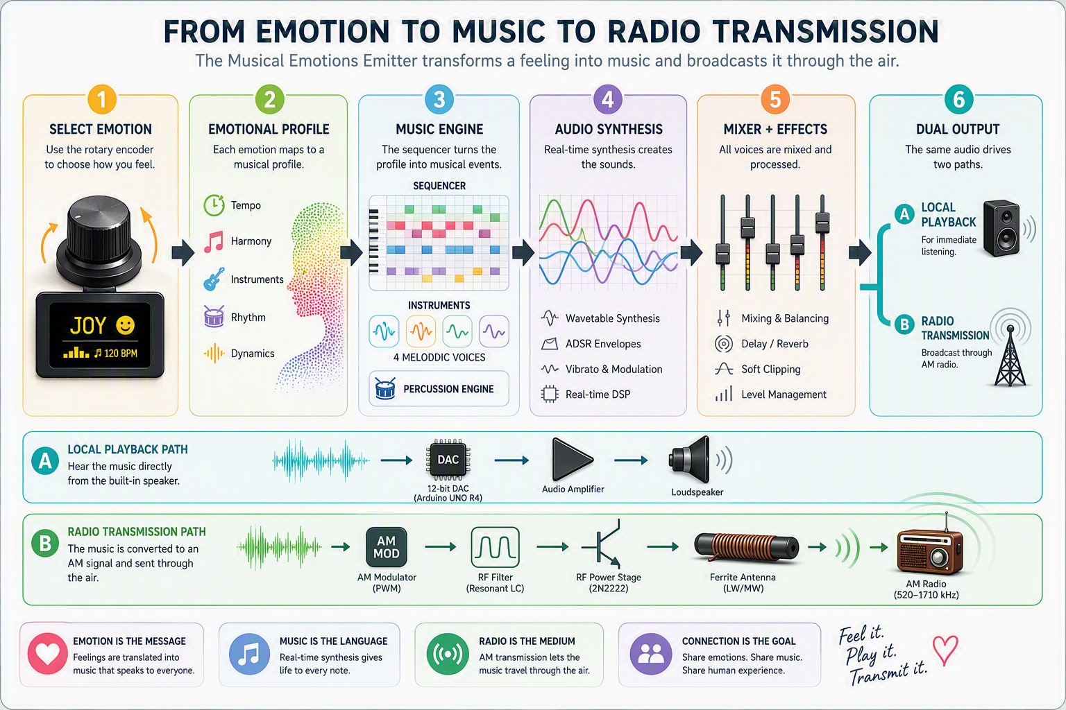
The synthesis engine runs at 16 kHz and supports up to four melodic voices plus percussion. Melodic sounds use wavetable synthesis; instruments define a waveform and parameters such as envelope, vibrato and level. Percussion is generated with oscillators, pitch sweeps, envelopes and noise rather than samples.
The sequencer schedules note and percussion events. The mixer combines the voices, balances levels and applies processing such as delay and normalisation. A circular audio buffer separates DSP generation from the time-critical output interrupt.
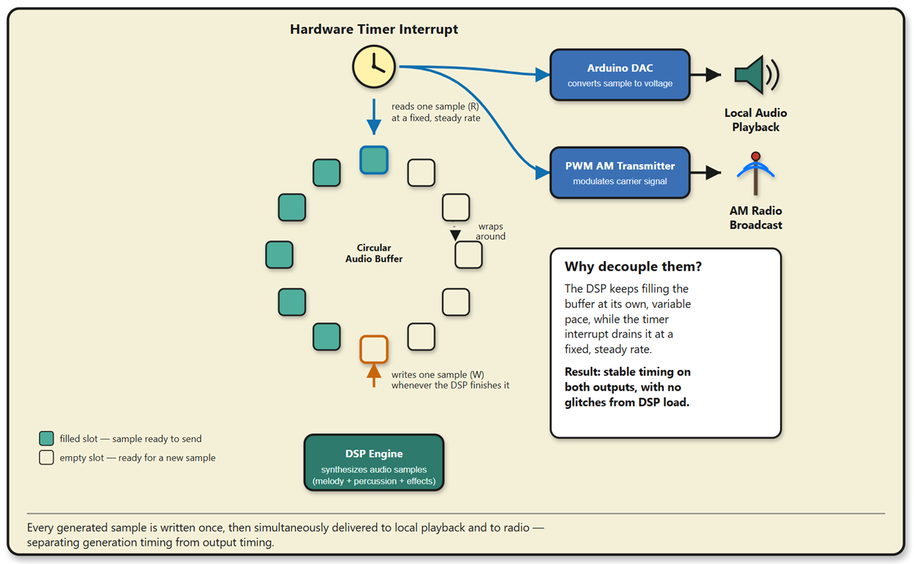
Circular buffer architecture used to decouple audio generation from audio output.
7.2 User Interface and Visualisation
The encoder controls emotion selection, playback, demo programs and settings. The OLED shows the selected emotion, playback state, transmission frequency and other information, and can display the generated waveform as a small oscilloscope.
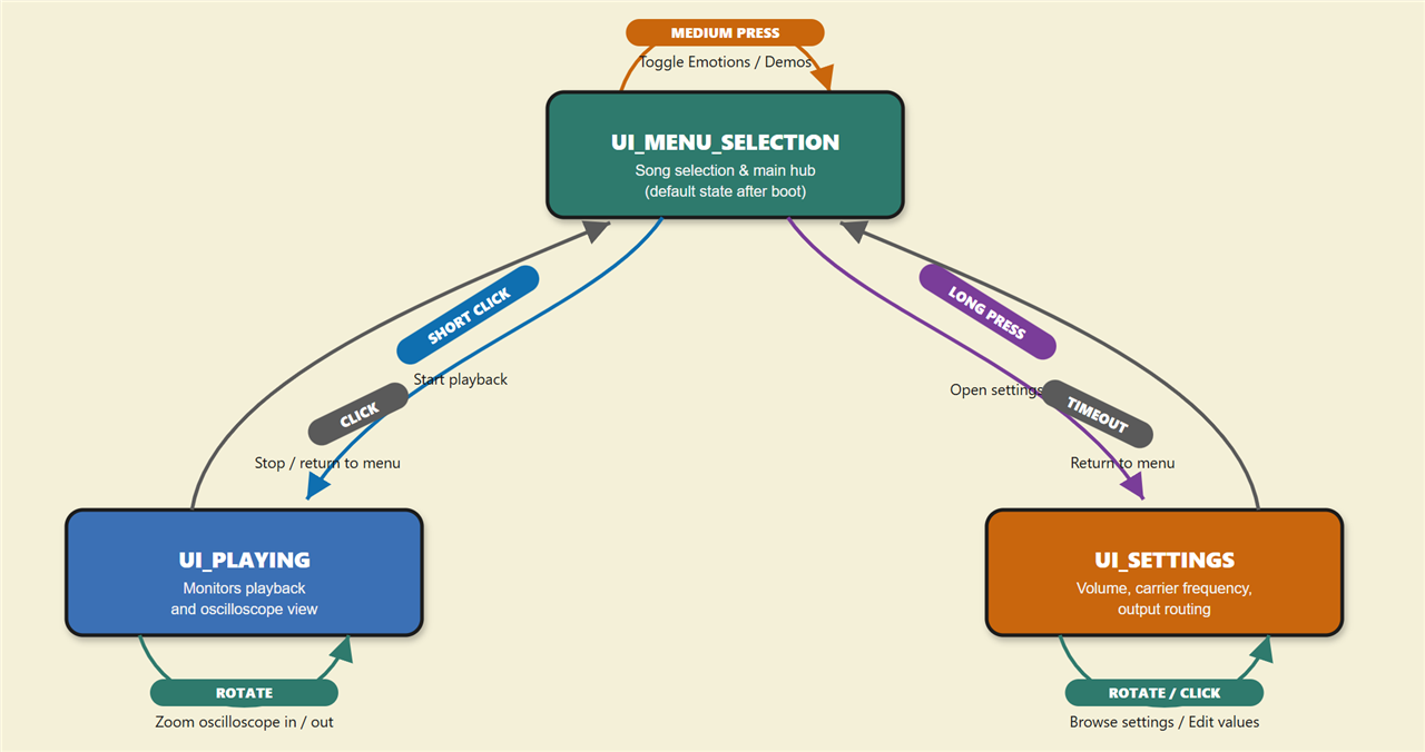
Navigation flow between Emotion Selection, Playback, Demo Mode, and Settings.
The available modes are Emotion Selection, Playback, Demo Mode and Settings. The oscilloscope is useful during development because it links the sound being heard with the signal being generated.
8. Web-Based Emulator
Musical Emotions Emitter AM Synth Emulator
The browser emulator was created to accelerate development and experimentation. Testing new instruments, DSP algorithms, interface concepts, and musical compositions directly on the Arduino often required repeated compilation and uploads. The emulator reproduces the main behavior of the hardware platform while providing a faster environment for exploration and learning.
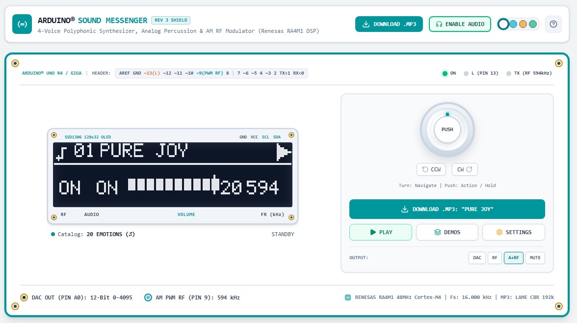
Web-based Musical Emotions Emitter emulator reproducing the behavior of the hardware platform.
The web emulator provides additional analysis and visualization tools beyond those available in the embedded system.
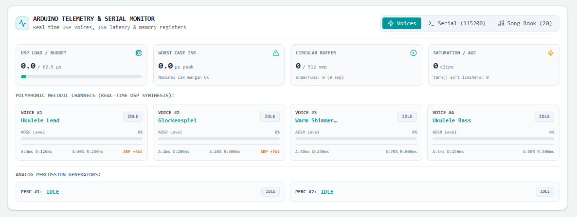
Telemetry & Serial Monitor Emulation. Real-time DSP voices, ISR latency & memory registers
8.1 Architecture and Development Platform
The emulator follows the same overall structure as the hardware implementation: composition library, sequencer, synthesis engine, audio processing chain, and AM transmission model. This architectural similarity allows ideas to be evaluated in the browser before being transferred to the Arduino firmware.
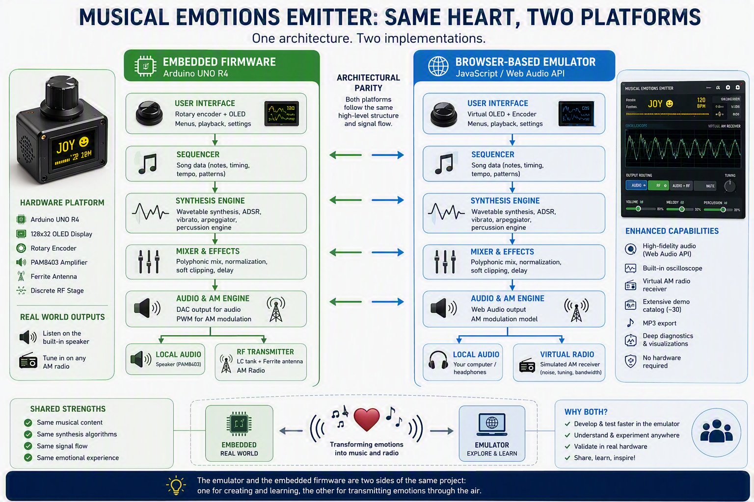
Relationship between the embedded firmware and the browser-based emulator.10.2 Virtual AM Receiver and AI-Assisted Development
The emulator includes a simplified AM receiver model with carrier tuning, attenuation, RF noise, bandwidth limits, envelope detection and interference. The recovered audio is intentionally different from the direct synthesizer output, making the effects of the radio path easier to hear.
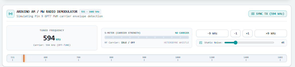
Simulated AM radio receiver used to explore the transmission process.
The emulator was also developed with an AI-assisted workflow. Engineering requirements and system behaviour were described through prompts, then the implementation was tested and refined. AI was used to explore UI ideas, DSP visualisations, educational demonstrations, audio processing and receiver simulation; engineering decisions and validation remained part of the development process.
9. Building the AM Transmitter With PWM
9.1 From Direct PWM to a Tuned Transmitter
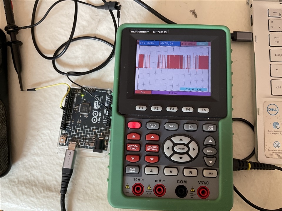
The first transmitter was deliberately simple: an UNO R4 timer generated a PWM carrier near 600 kHz and a short wire acted as the antenna.
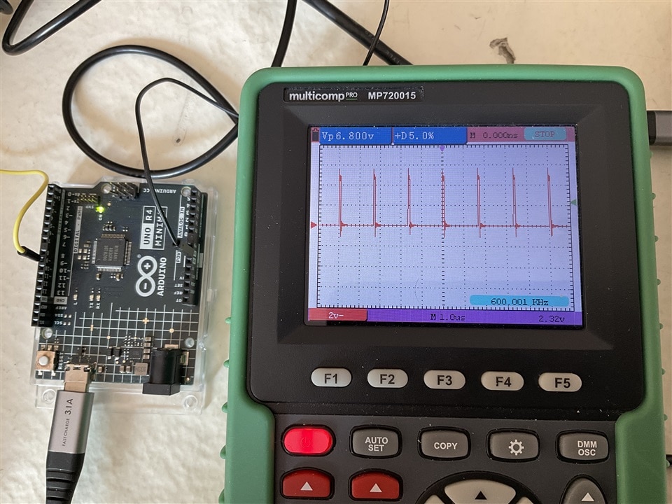
Two modulation tests were tried: switching between two duty cycles, and continuously varying duty cycle from a sine lookup table. Both produced an audible AM signal. The direct-PWM approach also showed its main limitation: the square-wave carrier produced significant harmonic energy away from the intended frequency.
| 1300 Hz tone | Duty cycle 5% | Duty Cycle 45% |
 |
 |
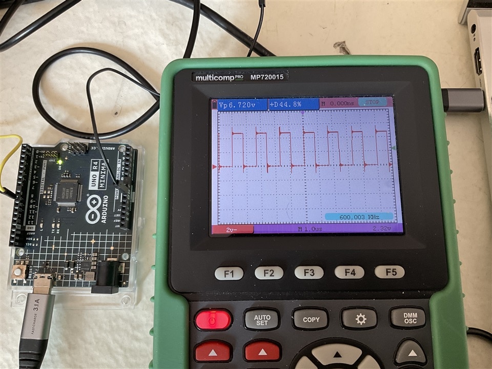 |
1300 Hz tone transmitted using PWM duty-cycle modulation.
9.2 Duty-Cycle Modulation and Harmonics
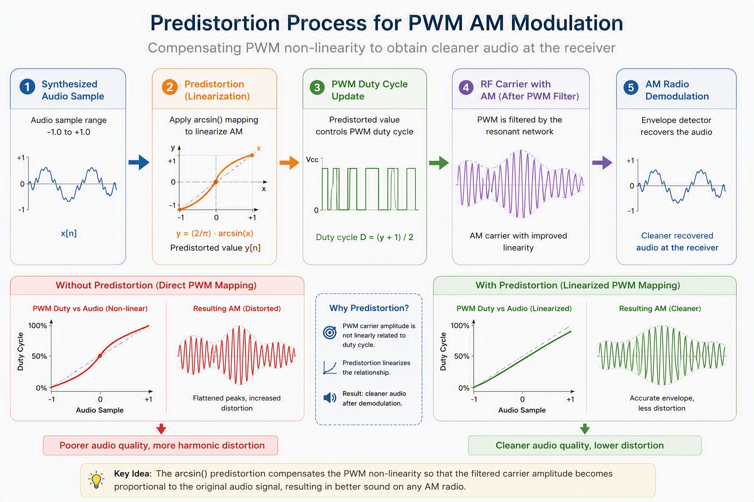
Audio samples are mapped to PWM duty cycle. A 32-bit phase accumulator steps through a sine lookup table in DDS fashion, producing a continuously varying modulation envelope. Because duty cycle and carrier amplitude are not perfectly linear, the firmware applies predistortion before updating the PWM hardware.
Audio samples control the PWM duty cycle, producing amplitude modulation of the carrier.
The raw PWM carrier also contains strong harmonics because it is a square wave.
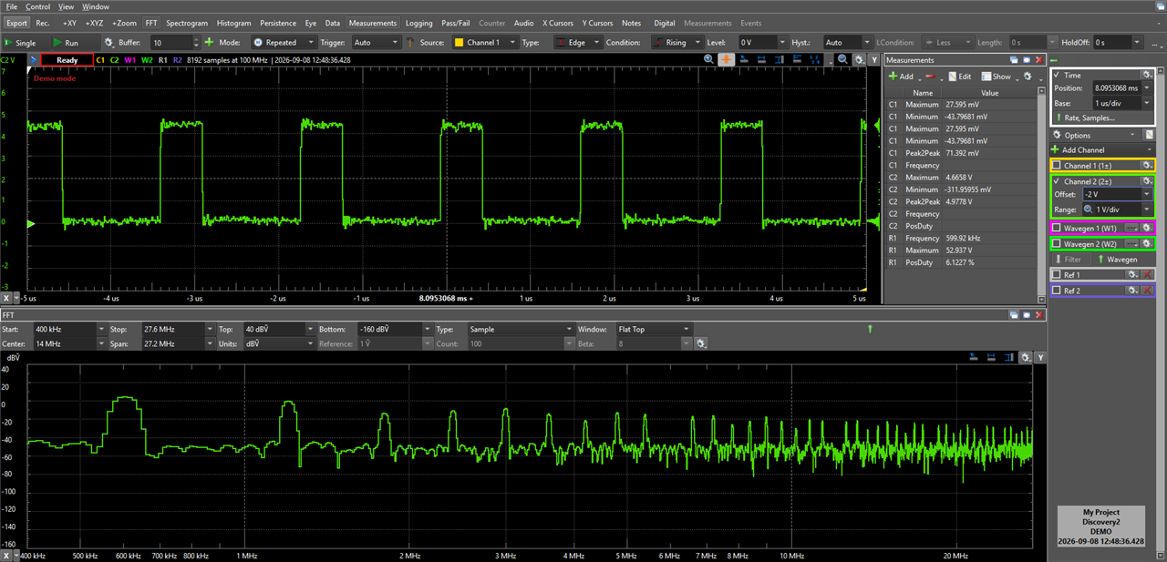
Spectrum of the unfiltered PWM carrier showing significant harmonic content.
9.3 RF Driver and Resonant Antenna
A microcontroller pin is not intended to drive a resonant antenna directly. For that reason, a 2N3904 driver stage was introduced between the Arduino and the tuned antenna network.
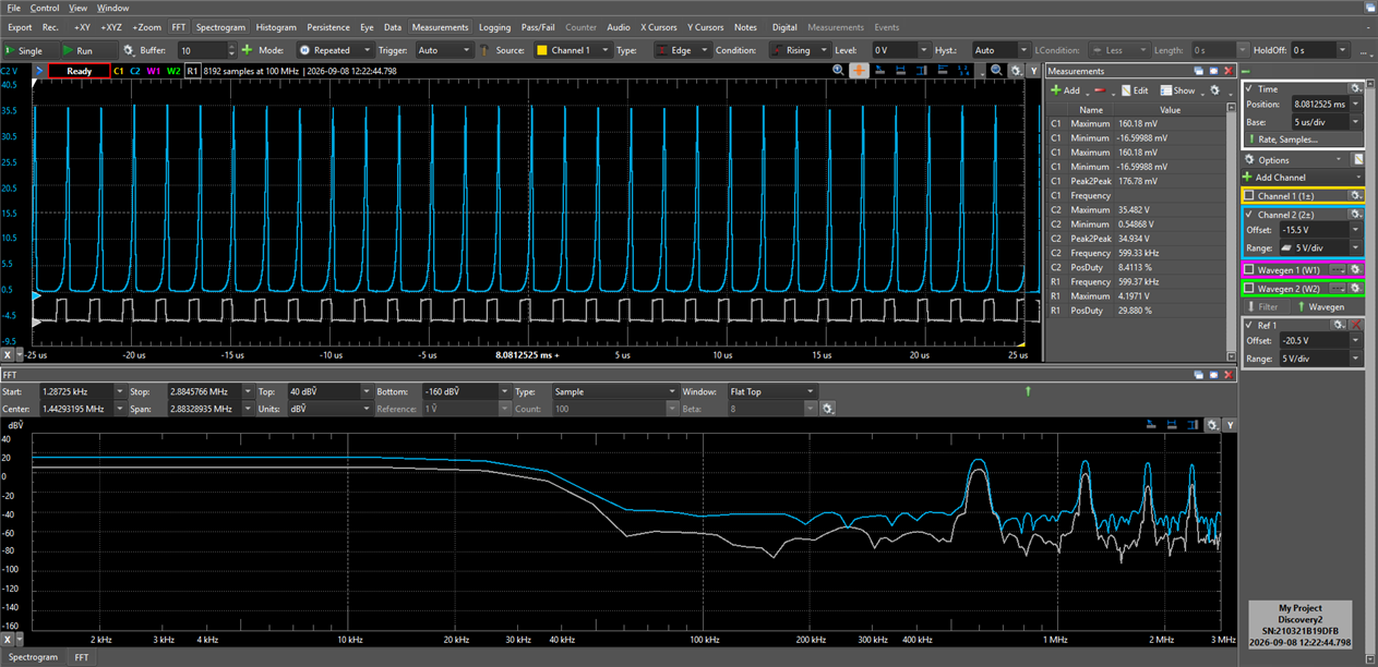
The resonant antenna described in Section 5.5 was then integrated into the transmitter and evaluated experimentally. The combination of the RF driver, ferrite antenna, and tuning capacitor provided better energy transfer, increased carrier amplitude, and significantly reduced harmonic content compared with the original wire-antenna experiments.
| Comparison between the Arduino PWM carrier and the signal measured at the transistor collector | Resonance measurements recorded while tuning the ferrite antenna. |
 |
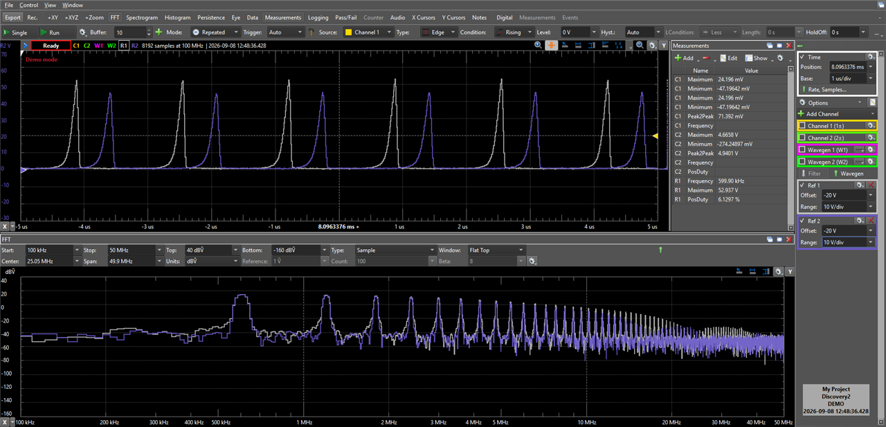 |
Measurements showed that tuning the LC network close to the carrier frequency increased RF voltage and improved reception quality on nearby AM receivers. Small changes in the tuning capacitor produced large changes in carrier amplitude. The maximum occurred when the LC resonant frequency was close to the transmission frequency.
The tuned network also attenuated many of the PWM harmonics. This was the main step from a detectable proof-of-concept signal to a cleaner medium-wave transmitter.
Compensating PWM non-linearity for AM Modulation
After filtering the PWM harmonics with the resonant RF stage, the relationship between duty cycle and carrier amplitude remains non-linear. The following predistortion process compensates for this effect, producing a cleaner AM envelope and more accurate audio reproduction.
10. Measurements and Results
Oscilloscope, inductance and spectrum measurements were used alongside listening tests to check the audio and RF chains.
10.1 Audio Validation and Clipping
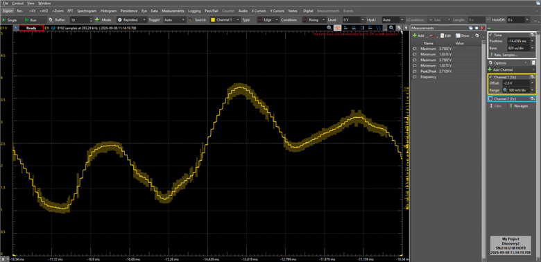
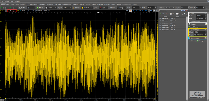
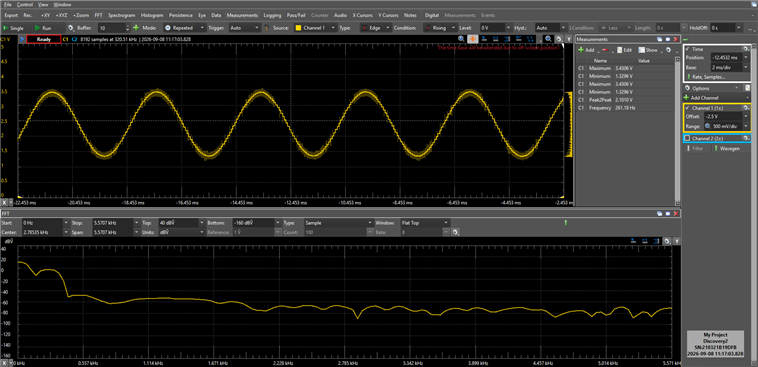
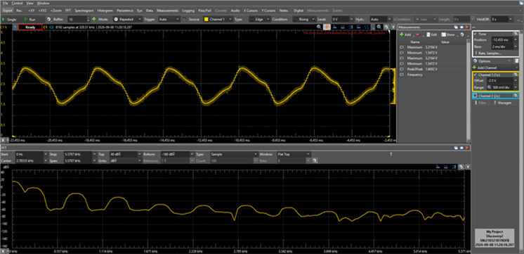
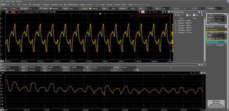
The DAC output was checked with an oscilloscope to verify the synthesizer waveforms and the complete DSP chain. Individual sine, triangle and square/other waveforms were measured, followed by actual musical playback.
| Synthesized audio measured during playback of an emotional composition. | Oscilloscope measurements performed at the Arduino DAC output |
|
|
 |
Synthesized sine, triangle & square waveforms measured at the DAC output after filter and effects processing.
| Sine | Triangle | Square |
 |
 |
 |
The browser-based emulator includes the same wavetable synthesis engine used by the hardware. The following demonstrations show three fundamental waveforms: sine, triangle, and sawtooth.
| Sine | Triangle | Sawtooth |
Detecting and preventing clipping
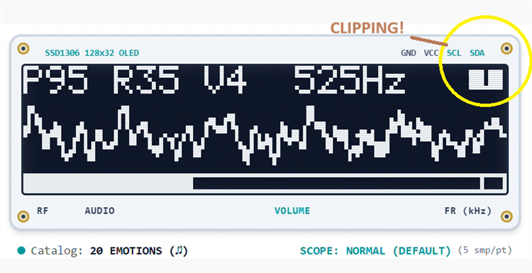
With several voices and percussion active, clipping can occur when the signal exceeds the available range. A soft-clipping stage reduces the harshness, and the OLED shows a clipping warning. Some test melodies deliberately retain clipping so the effect can be heard and identified.
| Video: Clipping demonstration |
Clipping warning indicator displayed during playback. |
 |
10.2 RF Validation
The Arduino output and the 2N3904 collector were compared. The Arduino produces the logic-level PWM carrier; the collector shows the larger voltage swings and ringing produced by the resonant network.
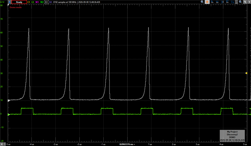
Comparison between the Arduino PWM carrier and the RF waveform measured at the transistor collector after the resonant network.
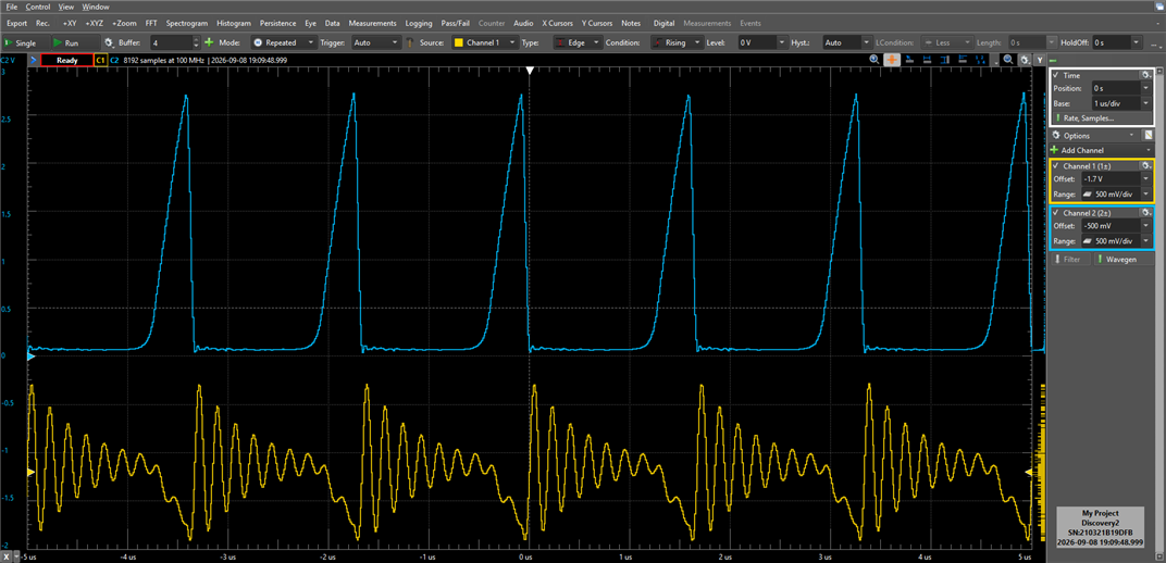
A secondary winding on the ferrite rod was used as a loosely coupled pickup coil, allowing the collector waveform and the magnetic signal at the antenna to be observed together.
Simultaneous observation of the collector waveform and the signal induced in a secondary ferrite winding.
Simultaneous measurement of the collector signal and the magnetically coupled pickup winding.
|
Comparison between the collector waveform and the magnetically coupled pickup signal. |
Frequency-domain comparison of the collector and pickup-coil signals. |
 |
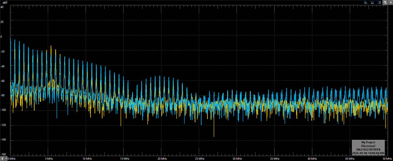 |
These measurements showed that energy from the switched carrier was being transferred into the resonant network and coupled into the ferrite antenna. With music playing, the duty-cycle changes were visible through the RF chain as AM variations.
10.3 Resonant Tuning and Reception
Adjusting the variable capacitor shifted the resonance of the LC tank and had a clear effect on the RF voltage developed across the circuit. As shown in the measurements and tuning graph, correct resonance produced a stronger and cleaner carrier.
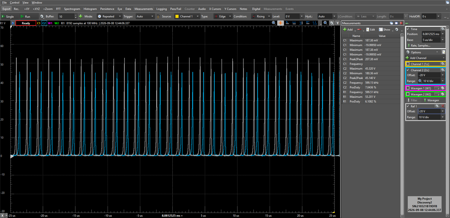
RF measurements performed while tuning the resonant LC network.
| Tuning Condition | Peak RF Voltage |
|---|---|
| Setting A | ~45 V |
| Setting B | ~55 V |
The best reception without any additional antenna was achieved by placing the transmitter and receiver ferrite rods parallel to each other. This configuration maximized magnetic coupling between both devices and provided the most reliable tuning results.
RF Range Measurements without additional antenna
| Distance | Reception |
|---|---|
| 0.5 m | Excellent |
| 1 m | Weak |
| 3 m | Not reliable |
Additional experiments used a loosely coupled four-turn secondary winding connected to several meters of insulated wire. Acting as a simple transformer and radiating element, this arrangement extended the reception range to approximately 5 m.
These tests confirmed that the synthesized audio could be successfully transmitted and recovered using a conventional AM radio receiver.
Regulatory Notice: This project generates a very low-power signal within the medium-wave AM band for educational and experimental purposes. Regulations governing unlicensed radio transmissions vary by country, so users should verify and comply with the applicable local requirements before operation.
11. Lessons Learned and Future Work
The main lesson from the RF work was that generating a carrier is easy compared with generating a clean and useful one. Resonance, filtering, antenna behaviour and measurements all mattered. Oscilloscope traces, inductance measurements and spectrum observations often showed problems that were not obvious from listening alone.
Limited hardware also shaped the design: storing musical data instead of audio kept memory use low, while salvaged radio components became part of the RF experiments.
Possible future work includes dynamic melody and harmony generation, adaptive rhythms, more instruments and effects, improved RF filtering and tuning, and further educational features in the emulator.
12. Conclusion and Further Exploration
The original question was simple: Could an Arduino generate a medium-wave radio signal directly? The resulting system combines a polyphonic synthesizer, PWM-based AM transmitter, tuned ferrite antenna, browser emulator and measured RF/audio behaviour.
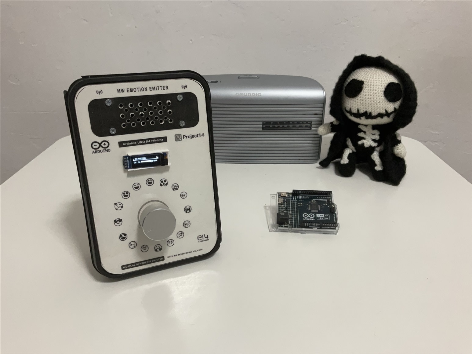
The completed Musical Emotions Emitter combining music synthesis, digital signal processing, and AM radio transmission.
The experiments also brought together modern digital hardware, salvaged radio components and a conventional AM receiver. Working on them with my son was part of how the project developed.
If you would like to explore more of our work, the following open-source projects cover music synthesis, DSP, FPGA audio generation, Direct Digital Frequency Synthesis (DDFS), and spectrum visualization.
- Building a Digital Synthesizer with FPGAs: The Minized Synth I Project - a digital synthesizer inspired by classic analogue instruments and implemented on FPGA hardware.
- Building Sounds with Hardware: An FPGA-Based Music Instrument Synthesizer - waveform generation, ADSR envelopes and hardware sound synthesis.
- DDFS: Direct Digital Frequency Synthesis for Sound - digital frequency generation techniques used in sound synthesis.
- FPGA ADSR Envelope Generator for Sound Synthesis - attack, decay, sustain and release for instrument synthesis.
- Sound Spectrum Visualizer with Arduino Nano 33 BLE - real-time spectrum analysis and audio visualisation.
element14 Project Archive: Five Years of Making & Sharing: My element14 Story - element14 Community
Hackster.io Project Portfolio: Enrique Albertos - Hackster.io
They cover Arduino and FPGA development, music synthesis, DSP, RF experimentation and educational electronics.
In this case, a simple radio experiment became a machine that turns musical data into a transmitted signal.


