

 Sensors Series - Part 11 - Current Sensing
Current sensing is an essential function in many power-management circuits. It gives designers a method to monitor the power consumption of their circuits and take action when needed. General applications utilizing current sensing include overcurrent detection, current control, and current management. Current sensing can largely be divided into two different categories, direct current sensing and indirect current sensing.
Related Components | Test Your Knowledge 
Indirect current sensing is generally used with motors and devices that consume a large amount of current. They operate on the principles of Faraday and Ampere’s Laws. Basically, a conductor carrying a current induces a voltage in a coil that is proportional to the current. Indirect current sensing does not interfere with the circuit operation and is completely isolated from the system. However, coils and sensors used for current sensing can be large and expensive.
Direct current sensing describes a method of monitoring current by placing a resistor between the power supply and the circuit (or load) consuming the current. Direct current sensing is based on Ohm’s Law and is a simple, low-cost solution. While this method does have drawbacks, such as a voltage drop across the resistor used, it is a very common and prevalent method for monitoring current on lower power PCBs.
Current sensing has also been a topic of renewed interest in recent times due to increased importance of green technologies. For instance, in electric vehicles, a precise discharge rate of batteries is important for reporting energy usage, energy storage, and maintaining the overall health of the battery. In addition, current sensing is critical in photovoltaic systems to improve efficiency and effectiveness of converting the DC voltages of solar panels into AC voltages that are eventually routed into the electric grid.
This learning module will cover some basic concepts around current sensing and introduce various techniques used for implementing current sensing in systems.
sponsored by 
2. Objectives
Upon completion of this module, you will be able to:
- Identify the common methods of current sensing
- Explain the different types of current sensing circuits
- Discuss various current sense ICs, their specifications, and what they are used for
- Talk about common applications for current sensing
3. Basic Concepts
There are three common methods used for direct current sensing: high side, low side, and full range (bidirectional) current sensing. In high side current sensing, a sense resistor is placed in series with the source of power and the load. Its advantages include the load being referenced directly to ground, and its ability to detect faults or shorts in the circuits. One of the downfalls of this method is high common mode voltage. On the other hand, low side current sensing places the sense resistor between the load and ground. This allows for a simple current sense circuit design, because it is ground referenced. Common mode voltage is also relatively low. However, the downsides of this method include the inability to detect a short in the load and the fact that the load circuits are no longer referenced to ground directly. Lastly, full range current sensing uses switches to combine high side and low side current sense techniques. This can offer advantages for specific use cases in which bidirectional sensing may be required; however, one potential problem that must be addressed in the design is the possibility of encountering large common mode voltage swings during operation. Simple schematics for all three of these methods are shown in Figure 1 to help the reader gain a better understanding of how these methods are used.
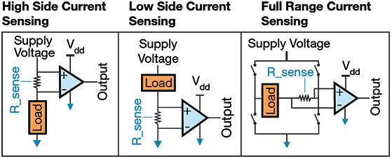
Figure 1. Direct Current Sensing Methodologies
A common element in all three of the above methods is the sense resistor. The sense resistor is an important piece of the current sensing solution and should not be overlooked. Since current will be passing through the sense resistor, there will be some amount of voltage drop across it. For this reason the resistor value chosen is generally small, somewhere between 10mΩ to 1Ω. It must also be capable of handling the power dissipated due to the maximum expected current. In addition, the tolerance and temperature coefficient of resistance (TCR) should also be considered when choosing a sense resistor, as both can introduce inaccuracies into the measurement circuit. TCR is generally specified in ppm per degrees, which should ideally be low. The higher the TCR, the more the resistance will change as a function of temperature. It is also worth noting that the copper that the device gets soldered onto will also have its own TCR, which can influence measurement accuracy.
Another common element in Figure 1 is the amplifying device. The amplifying device was traditionally implemented with op amps; however, various specialty devices are now available that support current sensing. Current sensing can be accomplished with op amps, difference amplifiers, instrumentation amplifiers, or devices known as current shunt monitors. Furthermore, depending on the device chosen, the output can be in the form of current, voltage, or a digital word.
Current shunt monitoring devices are generally the best performing devices for current sensing since they are specifically designed for the application. However, part availability, cost or additional constraints may make another amplifier better suited for the job. Regardless of the device to be implemented, there are some common performance characteristics that should always be considered. These include the following:
- Common mode voltage: The common mode voltage of the device must be capable of supporting the supply voltage of the application. For instance, if the supply voltage is 36V and high side current sensing is used, the amp’s input pins will have common mode voltages close to 36V present on them.
- Common mode rejection ratio (CMRR): Generally speaking, the job of the current sense amp is to amplify a small differential signal in the presence of a large common mode voltage. Ideally, any variation that is common to both inputs (noise) should not affect the amp performance. However, all devices have a finite amount of CMRR and errors can exist on the output due to common mode signals. For this reason, more common mode rejection is generally desirable.
- Input offset voltage: Since it is desirable to have the voltage drop across the sense resistor as small as possible, the input offset voltage of the amplifying device becomes more important. For example, if the voltage drop across the sense resistor is 100mV, then a 5mV input offset voltage (typical value for general purpose op amps) will introduce a 5% error in the result. This can lead to large inaccuracies and variations in systems.
- Slew rate and bandwidth: Slew rate and bandwidth are important to consider when changes in the output must be tracked quickly. Fast detection of overcurrent conditions would also require an amp with a larger slew rate and bandwidth. Slew rate refers to the maximum rate at which an op amp’s output can change due to internal compensation circuitry. Bandwidth refers to the op amp’s ability to settle to a specified output in some amount of time. Although closely related, one may dominate the other, so both should be considered in applications which require fast and precise measurement
The following section will cover some example circuits and techniques used for implementing current sensing circuits.
4. Analysis
- 4.1 Traditional Current Sensing
Although many specialty devices exist today specifically for current sensing, many times the traditional and simpler approach is more than adequate to fulfill your current sensing needs. The following will illustrate an example of this, as well as highlight some of the basic questions asked when designing a current sensing circuit.
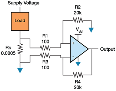
Figure 2. Low side current sensing circuit
Figure 2 illustrates the implementation of a low side current sensing circuit. The load current being monitored can be anywhere from 1A to 100A. In addition, it is constructed as a difference amplifier to counter any common mode effects due to ground leads. With a current sense resistor value of 0.0005Ω, the voltage drop across the sense resistor will be anywhere from 0 to 50mV. The gain of the configuration is determined by the ratio of R2 to R1. Thus, in the above example, the gain of the circuit is 200. As a result, the output voltage will vary between 0V and 10V depending upon the load current. For each application, the desired gain must be chosen to best fit the application’s needs. This is one of the design decisions an engineer will need to make.
We can also use the above circuit to analyze or better understand how an input offset voltage of an amplifier will affect the overall precision of the circuit. For example, at 10% of the maximum load current (10A), the voltage drop across the sense resistor will be 5mV. With the error due to the input offset voltage being the only consideration, achieving an accuracy of 1% would require an amplifier with a maximum specified input offset voltage of 50µV. That is a very low offset voltage for an amplifier to have. Typical general-purpose amplifiers may have offset voltages in the low millivolts range. However, there are precision op amps which provide offsets in the hundreds of microvolts, as well as an additional class of devices called chopper stabilized (Auto-Zero) op amps that feature input offsets in the low microvolt range.
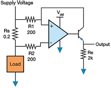
Figure 3. High side current sensing
The schematic in Figure 3 illustrates an alternative method of current sensing. For our quick analysis, we can assume the above components are all generic devices. The first thing to note is that this configuration is high side current sensing. We can begin analyzing this circuit by making the following assumptions: no current will flow into the op amp inputs, the op amp voltage inputs are equal (ideal op amp assumptions), and the base current into the NPN device can be ignored.
We can determine that the voltage at the negative op amp terminal is equal to the supply voltage minus the voltage drop across the sense resistor. Due to ideal op amp rules, this is also the voltage at the positive terminal. Thus, the current flowing through R1 is proportional to the current flowing through the sense resistor. Using Kirchoff’s current law, this current will flow into the collector of the NPN device and out the emitter, creating an output voltage that is equivalent to: Vout = (Re)*(Rs/R1)*(Iload). For the given resistor values in the example schematic, this equates to Vout = 2*(Iload).
The NPN device in Figure 3 acts as a means for the op amp to adjust the current flowing through R1. However, our assumption of no base current along with the finite current gain of the devices means a small error will be introduced into the circuit. For the op amp, a rail-to-rail input device must also be chosen since the inputs are close to the supply.
The LT1637 from Analog Devices is a good choice for this application. It is a rail-to-rail input and output op amp with input offset voltage of 350µV max, slew rate of 0.4V/µs, gain bandwidth product of 1.1MHz, and it can drive a large capacitive load. Furthermore, it is also capable of handling input common mode voltages as high as 44V. As a result, the aforementioned circuit can handle supply voltages in circuits up to 44V. Moreover, the device has a unique input stage that allows the same circuit to operate in what is called an “over-the-top” mode. Simply put, the op amp can be powered by a low voltage rail such as 3V, while its inputs can still accept input common mode and differential voltages as large as 44V.
- 4.2 Precision Current Sensing
Precision current sensing can be accomplished with more application specific devices and tighter tolerance components. In this section, we will cover a couple examples of precision current sensing circuits. The good device to mention first would be the LT6100 from Analog Devices. This device essentially combines all the components from the previous example into a single package and adds a couple more features. A block diagram showing some of the components inside the device is shown in Figure 4.
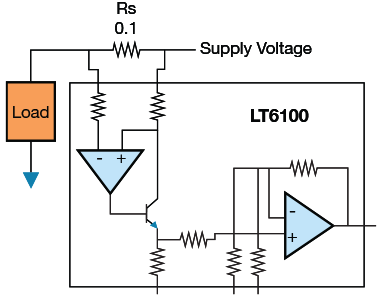
Figure 4. Precision current sensing circuit using the Analog Devices LT6100
This device is meant to be used in high side current sense application and is best suited for battery-powered applications with supply voltages from 4.1V to 48V. It features a maximum input offset voltage of 300µV (80µV typical) and can provide a gain accuracy of 0.5% due to integrated on-chip, gain-setting resistors. It also provides very high common mode rejection and supply rejection, with typical values being 120dB. The gain of the device can be set by connecting specific pins to ground or leaving them open. The overall gain of the device can be set to six different values ranging from 10 to 50.
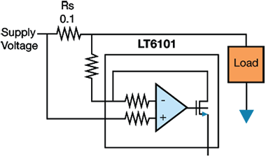
Figure 5. Precision sensing circuit using the Analog Devices LT6101
The LT6101 is a similar solution. The components are very similar, however, the LT6101 has a current output and does not include on-chip resistors for setting the gain. The LT6101 allows the user more flexibility in choosing the gain. With appropriate use of tight tolerance resistors, a high precision current sense solution can be implemented, similar to the LT6100. Both feature fast 1µs response times that make them well-suited for fast circuit protection applications. As can be seen in Figure 5, input matched resistors, the amplifying device, and an output transistor are all integrated into a single package.

Figure 6. Diagram showing the Analog Devices LTC6800 used in a current sense application
One final device we will cover which allows for precision current sensing is the LTC6800. This device integrates a zero-drift instrumentation amplifier and rail-to-rail inputs and outputs. The gain of the device is set by an external voltage divider, which also determines the gain accuracy. What makes this device unique is that it uses internal capacitors and sampling at its input to achieve very high common mode rejection, very low input offset voltage, and minimum offset voltage drift. This does place a major tradeoff on the device though. Since the input is sampled, the output is discontinuous, thus limiting the bandwidth. As a result, this part is only suitable for low frequency applications.
- 4.3 Advanced Current Sensing
There are advanced current sensing solutions that offer more complex functions for managing power. Like the precision devices previously discussed, these modern ICs integrate many of the components needed for functionality inside the chip, allowing high accuracy, better reliability, and improved performance. Some advanced current sensing applications include bidirectional sensing, fault protection, hot-swap controllers, fuel gauges, battery management circuits, and power amplifier controllers.
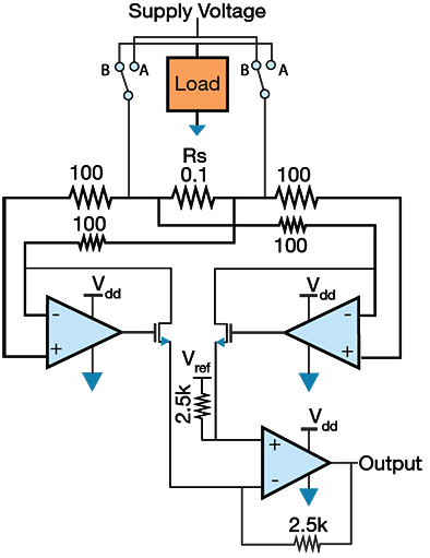
Figure 7. Bidirectional current sensing
Figure 7 illustrates a method of implementing bidirectional current sensing. This is similar to the full range current sensing previously mentioned in Basic Concepts. Switches are used to change between high side current sensing and low side current sensing. In addition, two single-ended amplifier devices feed a single amplifier to produce a single-ended output. The final amplifier device has a reference input voltage supplied to one input. As a result, when switched to high side current sensing, the output voltage will move between the reference voltage and the supply. On the other hand, when switched to low side current sensing, the output will be between 0V and the reference voltage. This technique basically combines two of the aforementioned “basic” current sensing circuits into a more complex solution to allow for bidirectional sensing.
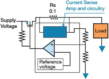
Figure 8. Basic circuit used to implement fault detection and current monitoring
Some products exist that integrate fault detection circuits into the device. One such example is the MAX4373. This device allows users to set a fault current using external resistors. Thus, when the device detects that the current through the sense resistor is larger than the current dictated by the external resistors, an internal comparator turns off a PMOS device that is in series with the supply. For this specific device the comparator can be reset by toggling a pin or by power cycling the circuit. This device allows for a standalone solution for cutting off power, protecting a load in the event of a fault.
Additionally, hot-swap controllers find use in many applications. These devices allow pieces of a system to be inserted or removed during operation without interrupting a system’s overall functionality. For example, if a daughter card is inserted into a motherboard during operation, it can create a momentary inrush current that can cause the supply voltage to drop. Additional unintended events such as short circuits and overall system malfunctions can also occur. To mitigate some of these challenges, devices known as hot swap controllers are used. These devices monitor different parts of the power system. When a sudden inrush current is detected, they can filter and bring the current to a safe level. In addition, if a fault or power error is detected, they can turn off parts of a system to isolate different areas from one another. Hot swap controllers integrate many complex features such as timers, FET driver circuits, digital IO, current control circuits, and, of course, current sense circuits.
The last area of devices that we will mention are fuel gauges and battery management systems. Like hot-swap controllers, these devices integrate several different circuits and can quickly become complex. Stated simply, they exist to optimize system performance and prolong battery life. Since many modern electronic devices are now battery-powered (even cars), fuel gauging devices have become more important than ever. They must also operate with very high precision in some systems, such as EVs, to let the driver know precisely how much energy is left and how much further they can drive.
Fuel gauges and battery management systems essentially combine all of the aforementioned technologies. Bidirectional current sensing is used to monitor and supervise battery charging and discharging. Additionally, an internal circuit known as a coulomb counter measures the current/net flow in a charging or discharging cycle. This allows it to calculate when a battery is fully charged or fully discharged and report the overall charge within the system. These devices also typically provide options for overload and short circuit protection, allowing a user to shut down parts of a system or isolate the battery completely from the system. Since these devices can perform so many functions, they generally have digital interfaces for programming and configuring. They may interface directly with a microcontroller, allowing system status, current draw, and charge information to be read directly without the need for any analog to digital conversion.
5. Conclusion
Overall, this document has covered the basic concepts of current sensing and its applications. In addition, we have covered various circuits that can be used for current sensing solutions that range from a simple op amp and a couple transistors to as complex as a complete system-on-chip. The end application will always dictate how complex a current sensing solution needs to be. The reader should now have a fundamental understanding of the concepts and circuits required to begin implementing power management systems.
*Trademark. Analog Devices is a trademark of Analog Devices, Inc. Other logos, product and/or company names may be trademarks of their respective owners.
Test Your Knowledge
Sensors XI

Are you ready to demonstrate your Current Sensing essentials knowledge? Then take a quick 10-question multiple choice quiz to see how much you've learned from this module.
To earn the Essentials Sensors 11 Badge, read through the learning module, attain 100% in the quiz at the bottom, and leave us some feedback in the comments section below.
Top Comments