

 Sensors Series - Part 5 - Flight Sense
Distance measurement and range detection methods are not new. They have been used for decades in almost every engineering field, including robotics, presence detection, optical navigation, medical tech, and automotive applications. Multiple detection techniques can determine in real-time the proximity of an object or objects. Distance sensors incorporate diverse technologies like infrared (IR) triangulation, laser, ultrasonic, and Time-of-Flight (ToF). A ToF sensor accurately detects objects in an instant and remains unaffected by humidity, air pressure, and temperature, making it suitable for both outdoor and indoor use. It offers precise, accurate distance measurements. The technology is immune to ambient illumination, optical path variations (glass or plastic covers, for example), and is independent of target object reflectance. In this learning module, we will discuss the basic concept of ToF sensors, methods to measure the time of flight, the different techniques in range sensing, the challenges and designs of ToF sensors, and a few use case applications.
Related Components | Test Your Knowledge 
sponsored by
2. Objectives
Upon completion of this module, you will be able to:
- Explain the technologies used in light-based range sensing
- Understand the working principle of ToF sensors, measurement methods, and their challenges
- Discuss ST's ToF proximity and range sensors and its patented FlightSense
 Technology
 - Discuss ToF sensor applications
3. Scope
Distance or range sensor devices determine the proximity of an object without any physical contact. Figure 1 shows human collaborative robots (HCRs), which partner with humans in the same workspace. Space-saving and workability are expected from such robots. This system consists of various proximity and range sensors for workability and safety in collaboration with humans. Range sensors are different from other proximity sensors that use simple IR (Infra-Red) technology, which only measure signal strength and can be affected by the object's reflectivity. The other technologies used for proximity and range sensing are capacitive and ultrasonic.
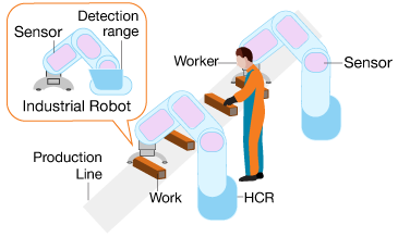
Figure 1: Human Collaborative Robot with proximity and range sensor
Three principal technologies are commonly used for range sensing dependent on laser light: Triangulation, Time of Flight, and Modulation. Based on the principle of stereo vision, triangulation range sensors make it possible to obtain range information from various sensors. Two or multiple input images are used to estimate the distance to points in any scene, making a triangle between the two camera points and the scene point. A significant flaw in triangulation technology is the correspondence problem: given a particular point in one image, it can be time consuming to locate the identical point in the other camera, and thus it is hard to ascertain the accurate depth.
Modulation range sensors are usually of two types, where a continuous laser signal is either frequency- or amplitude-modulated. The signal transit time is estimated by keeping a tab between the outgoing and the return signals, and by extension, the target distance.
Time-of-Flight (ToF) range sensors calculate distance by measuring the time that a pulse of light spends to travel from the source to the observed target and then to the detector. Laser-based ToF range sensors are also known as light detection and ranging (LiDAR) or laser radar (LADAR) sensors. This technology revolutionized the machine vision industry, as it provided 3D imaging through an inexpensive CMOS pixel array together with an active modulated light source. The ease of use and compact construction, together with high frame-rate and accuracy, make ToF cameras a preferred solution for a broad range of applications. The scope of this learning module is limited to ToF-based proximity and range sensors designed by STMicroelectronics, its patented FlightSense (ToF) technology, design considerations, applications, and the development ecosystem to evaluate these sensors.
4. Basic Concepts
ToF technology is based on the distance measurement method between a sensor and an object. This method uses the time difference of the sensor emitting the signal, and its return after an object reflects the signal. Light is the standard signal used.
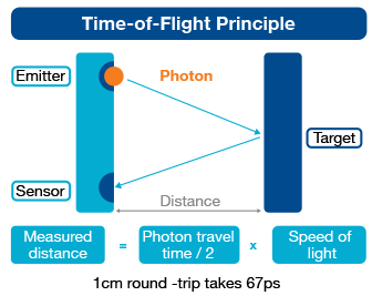
Figure 2: ToF Principle
The procedure is described in Figure 2, where a laser focuses light or photons towards a target. A few quanta of light, after their collision with the target, are reflected into the sensor. The flight time is consequently calculated by the following formula:
Distance Value = Photon travel time/2 x the speed of light
- 4.1 Direct and Indirect Measurement of ToF
ToF sensors measure distances using the time it takes for photons to travel between two points. Two methods can be used to measure this time: direct or indirect. ToF sensors based on both techniques offer particular advantages in specific contexts. Both simultaneously measure distance and intensity for each object pixel.
Direct ToF sensors transmit short light pulses that last just a few nanoseconds and, subsequently, measure the time it takes for the emitted light to return. Time is measured directly through an accurate time base. LiDAR is an example of a direct ToF sensor. Unfortunately, direct ToF is harder to design and, therefore, does not scale well to high resolutions.
Indirect ToF sensors transmit continuous, modulated light. The reflected light's phase difference is measured to calculate how far an object is. A phase in the light wave is a specific point in time on the waveform cycle and is measured as an angle in degrees. A complete cycle comes to 360°. Figure 3 illustrates a phase difference between the emitted light (indicated in green) and the received light (shown in blue).
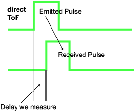
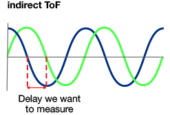
Figure 3: Direct and Indirect Time of Flight Measurement
Indirect ToF sensors emit set frequency-modulated light and are in phase. The wave frequency decides the distance it takes for the emitted wave to achieve a full cycle. To give an example, a 100 MHz wave takes about 3 m to complete an entire cycle and come back to its initial phase. The formula to be employed is:
distance = speed x time
Where speed refers to light speed = 3x10⁸ m/s, and time (T) equals 1/f = 1/100 MHz = 10-8 s
Thus distance = 3x108 x 10-8 = 3 meter
So if the wave completes one full cycle for a round trip from emitter to object and then from the object to the receiver, the object distance comes to 3/2 = 1.5 meter.
Indirect ToF offers significant advantages, such as higher resolution when compared with direct ToF, low-frequency light use, and 'slow' illumination. The ToF can also be effortlessly scaled up to multi-pixel 3D cameras.
- 4.2 The Effect of Detecting-Object on ToF Measurement
Dissimilar surfaces reflect light in different ways, and the object hit by the photons inevitably has unique characteristics. Light may be absorbed, reflected, or transmitted when it reaches a surface. The fraction of light reflected by that surface is called reflectance. However, reflectance also depends on the type of reflected light, with surface reflectivity being different for near-infrared and visible light. ToF measurements can run into significant complications for irregular surfaces, as the sensor finds it difficult to find the origin of individual photons. Photons can bounce off walls in confined spaces and from other objects, leading to further confusion of measured distance.
- 4.3 The Effect of the Environment on ToF Measurements
Indirect ToF has its advantages and limitations. The light may reflect off diverse objects with different reflectivity and at different distances; this means that the sensor receives light with different phases and intensities but is unable to figure out that the light has come from two objects. The waves join due to the 'superposition principle.' The sensor will compute a distance that comes to the average of all distances in its field-of-view.
- 4.4 ToF Sensor Challenges
Challenges associated with ToF sensors are illustrated in Figure 4. The complete system consists of a transmitter, a reference, and a receiver. A cover glass is placed over the sensor. Two cones are observed: a sensor field of view cone and a VCSEL cone. The actual return path should be similar to the green path, but the light shining directly (as light green shown in the figure) on the reference array creates a false reference.
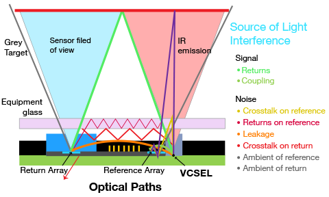
Figure 4: Challenges with ToF measurement
Other problems include optical noise like crosstalk (the undesirable coupling among optical signals). During crosstalk, a small portion of power from one optical signal is directed to another optical signal, thus creating noise.
The photon bounces from cover glass to reference. This creates crosstalk on the reference. A chance exists that the photon may reflect on referencing from the object, and returns may be created on the reference. Leakage problems may come to the fore when the photon internally travels from the VCSEL to the receiver. Crosstalk may occur if the photon bounces from both surfaces of the glass cover and to the receiver. The receiver and reference sense the ambient light, which also creates a challenge for proper measurement. A ToF sensor with a crosstalk problem always scans two targets: (1) the fixed distance giving product-level cover (glass/plastic) with comparatively fixed optical characteristics, and (2) the actual target that offers varying distance and optical characteristics.
5. Analysis
ST Microelectronics offers a wide array of proximity and range sensors, including the VL6180, VL53L0X, VL53L3CX, VL53L1X, and VL53L1CB series sensors. All are based on ST's patented FlightSense Technology. ST also provides the ecosystem of the STM32 Open Development Environment and development boards to evaluate these sensors. Here, we will discuss these sensors with their structure, features, and use case applications, along with their expansion and development boards.
The ST FlightSense time of flight sensors use a Vertical-Cavity, Surface Emitting Laser (VCSEL) as a transmitter and a Single Photon Avalanche Diode (SPAD) as a receiver. The VCSEL emits photons that propagate towards the target and return to the SPAD after reflection. The SPAD array generates a small pulse on each detected photon. The time between initial and received pulse is converted into distance.
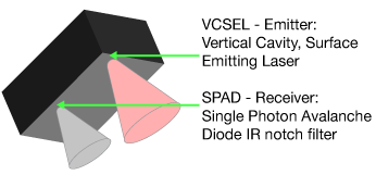
Figure 5: Components of ST's FlightSense Time of Flight Sensor
- 5.1 Vertical Cavity Surface Emitting Diode (VCSEL)
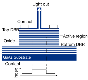
Figure 6: VCSEL Structure
A VCSEL is a semiconductor laser diode with a monolithic laser resonator that emits light in a direction perpendicular to the chip surface. The cavity (resonator) is engineered with two semiconductors. These are Bragg mirrors (distributed Bragg reflector lasers). The mirrors contain a gain structure (active region) with multiple quantum wells and a total thickness of only micrometers. A small amount of power (few tens of milliwatts) is electrically pumped into the active region generating an output power in the higher power (0.5-5 mW) range for multimode devices. The application of current is through a ring electrode, through which an output beam can be extracted, and the current is confined to the resonator mode region using electrically conductive (doped) mirror layers with the isolating material encasing them. Figure 6 illustrates the VCSEL's internal structure.
VCSELs have high beam quality primarily for small mode areas, and consequently suffer from output power limitations. Excitation of the higher-order transverse modes is unavoidable for larger mode areas. Their standard emission wavelengths are in the 850nm–940nm range (ST), as obtained with the GaAs/AlGaAs material system.. However, longer wavelengths like 1.3 µm, or 1.55 µm, can be obtained with dilute nitrides and from indium phosphide based devices.
VCSEL arrays generate considerably more power. A 2-D VCSEL array having many thousands of emitters with a small spacing can emit tens or hundreds of watts continuous-wave. VCSEL arrays, in comparison with conventional edge-emitting laser diodes, typically suffer from lower power conversion efficiency. However, there can be substantial application advantages, such as simplification of beam shaping optics.
- 5.2 Single Photon Avalanche Diode (SPAD)
SPADs are CMOS semiconductor devices. They are based on a p-n junction reversed biased at a voltage higher than the breakdown voltage. The electric field at this bias is so high that a single charge carrier injected into the depletion layer may initiate a self-sustaining avalanche. This current rises quickly to a steady macroscopic level, in the milliampere range. If it is a photo-generated primary carrier, the leading edge of the avalanche pulse marks the detected photon arrival time. The flow of current continues until the avalanche is satisfied by lowering the bias voltage down to or below the breakdown voltage. The lower electric field is now unable to accelerate the carriers to impact-ionize with the lattice atoms resulting in the current being switched off. The bias voltage should be raised again above the breakdown if it is needed to detect another photon.
- 5.3 FlightSense Technology
ST's proprietary FlightSense technology is a ToF-based direct distance measurement technique, independent of target size, color, and reflectance. It provides a fully integrated ToF module with superfast processing and minuscule power consumption. The third-generation FlightSense sensor is equipped with new patented silicon- and module-level architectures, as well as optical lenses in the module. This synthesis boosts core performance, while introducing multiple new features, including multi-target detection and cover-glass crosstalk immunity at long distances. Such advances deliver better sensor performance for robotics, user detection, drones, IoT, and wearable applications. The following table compares ST's FlightSense sensor with other range sensing technologies.
| Capacitive | Ultra-Sonic | Conventional IR | ST FlightSense |
|
|---|---|---|---|---|
| Size/Weight | Small/light | 2xToF/Heavy | Small/Light | Small/Light |
| Mechanical Integration | Complex (antenna) | Complex (large module) | Easy (if all-in-one) | Easy (all in one, reflowable) |
| Signal Amplitude | No | Yes | Yes | Yes |
| Real distance output | No, very imprecise | No (computed) | No (computed) | Real distance in mm (readeable thru I2C) |
| Minimum distance | 0cm | 10cm | 0cm | 0cm |
| Maximum distance | Few cms | Up to 1.5m | 20cm | up to 4 meters (1) |
| Reliable (Vs objects color and reflectance) | No. May detect target in all directions around antenna | No, impacted | No, impacted | Yes, even black (3%), gloves, etc. |
| Reliable (Vs material finish / roughness) | No. Sensitive to body or object charge | No. Isotropic, impacted by wide sound | No. Angular dependency | Yes, with angular dependency |
| Gesture control - Tap vs. Swipe | Yes | No | Yes |
Table 1: Comparison of Range Sensing Technologies
We will now discuss some example sensors based on this technology, with some use cases.
- 5.4 VL6180 Series Sensors
The VL6180 series sensors are ST's 1st generation ToF proximity sensors based on FlightSense technology. They can be interfaced with a microcontroller via the industry-standard I2C bus. They combine an IR emitter, a range sensor, and an ambient light sensor in a three-in-one ready-to-use reflowable package, making them easy to integrate. They save the end-product maker long and costly optical and mechanical design optimizations. These modules are designed for low power operation. Ranging is automatically performed at user-defined intervals. Multiple thresholds and interrupt schemes are supported to minimize host operations. These sensors are used in smartphones, portable touch screen devices, tablets/laptops, and gaming devices. Figure 7 shows the internal structure and a recommended application circuit.
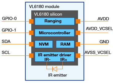
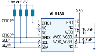
Figure 7: VL6180 internal block and application circuit
- 5.5 VL53L0X Series Sensors
The VL53L0X is a 2nd generation ToF laser-ranging module that integrates a leading-edge SPAD array and offers accurate distance measurement independent of target reflectances. It measures absolute distances up to 2m and includes the I2C interface for device control and data transfer, Xshutdown (reset), interrupts GPIO, and Programmable I2C address. The VL53L0X's 940 nm VCSEL emitter is invisible to the human eye, coupled with internal physical infrared filters. It enables longer ranging distances, higher immunity to ambient light, and better robustness to cover glass optical crosstalk. Figure 8 shows the internal structure and recommended application circuit for this module. STM32 Nucleo boards, the X-NUCLEO-53L0A1 expansion board, and the 53L0-SATEL-I1 breakout board create an evaluation ecosystem for this module.
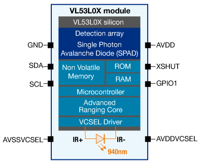
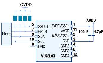
Figure 8: Internal block diagram and application circuit of the VL53L0X module
- 5.6 VL53L1X Series Sensors
The VL53L1X series is the 3rd generation ST ToF sensor with an in-built lens. This sensor module incorporates a new lens system, a 940nm VCSEL invisible-light source, a processing core, and an SPAD photon detector. The addition of the optical lens system improves the photon detection rate, which boosts the module's ranging performance. The in-built microcontroller accomplishes the complete ranging function. The microcontroller runs digital algorithms to minimize host-processing overhead and system power consumption, maximizing battery life for mobile applications.
A good use case of this sensor is to count people crossing a predefined area, such as a meeting room entrance or a particular location in a corridor. The sensor is set on the top of the area to be tracked, as shown in figure 9.
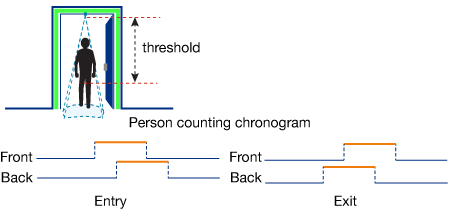
Figure 9: People Counting System
This system uses the multiple zones of the sensor receiving the SPAD area, and configures it with two discrete fields of view (FoVs) to alternatively obtain a ranging distance and, by consequence, recognize a person's movements. This method allows us to know the population of a meeting room at all times by detection of attendees' entrances and exits.
A simple algorithm can be made by measuring and analyzing the distances of targets within the FoV’s front and back zone, which detects a person's direction when that individual crosses the area below the two FoVs. This algorithm understands that someone is below one of the FoVs as long as the distance measured is between 0 and a specified threshold value. The sensor, from a timing perspective, alternatively ranges on each of the two zones, for a minute measured in milliseconds. It is possible to determine in which direction a person crossed the area, depending on which order this person was detected in the two zones, as shown in Figure 9.
The ecosystem is built using a development board, expansion board, and a breakout board, as shown in figure 10. The software code example runs proof of concept. This software runs on a NUCLEO F401RE board and is accompanied by one X-NUCLEO 53L1A1 expansion board. The VL53L1X "left" satellite is the one enabled by the software example.
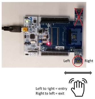
Figure 10: NUCLEO F401RE, X-NUCLEO-53L1A1, and VL53L1X break-out boards (Source: UM2600)
- 5.7 VL53L1CB Series Sensors
The VL53L1 is a state-of-the-art, Time-of-Flight (ToF), laser-ranging, miniature sensor with with advanced multi-zone and multi-object detection, enhancing STMicroelectronics' FlightSenseShop Now product family. Housed in a miniature and reflowable package, it integrates a SPAD (single photon avalanche diode) array, physical infrared filters and optics to achieve the best ranging performance in various ambient lighting conditions, with a wide range of cover windows.
Unlike conventional IR sensors, the VL53L1 uses ST's latest generation direct ToF technology which allows absolute distance measurement whatever the target color and reflectance. It provides accurate ranging above 4 m and can work at fast speeds (60 Hz), which makes it the fastest miniature ToF sensor on the market. With patented algorithms and ingenious module construction, the VL53L1 is also able to detect different objects within the field of view with depth understanding at 60 Hz. Scene browsing and multi-zone detection is now possible with the VL53L1, thanks to software customizable detection array for quicker "touch-to-focus" or mini depth-map use cases.
Now we will discuss some applications based on the ToF sensors.
- 5.8 Smart Parking Using the VL53L3CX ToF Proximity Sensor
The VL53L3CX is a Time-of-Flight (ToF) sensor with multi target detection and embeds ST's third generation FlightSense patented technology. It combines a high performance proximity and ranging sensor, with multi target distance measurements and automatic smudge correction. The miniature reflowable package integrates a single photon avalanche diode (SPAD) array and physical infrared filters to achieve the best ranging performance in various ambient lighting conditions, with a wide range of cover glass windows.
The VL53L3CX combines the benefits of a high-performance proximity sensor, with excellent short distance linearity, together with ranging capability up to 5m. With patented algorithms and ingenious module construction, the VL53L3CX is also able to detect different objects within the field-of-view (FoV) with depth understanding. The ST histogram algorithms allow cover glass crosstalk immunity beyond 80 cm, and dynamic smudge compensation.
This smart parking application helps users find a suitable parking area, make reservations, and also extend them if needed. Parking administrators can define parking spaces, manage them, and even authenticate users against reservations when they access the parking area. The users take advantage of location-based information and also request system services through mobile applications. Parking operators use mobile applications to verify reservations. In contrast, parking admins use a web application to manage the parking area. Figure 11 shows a system block diagram using the VL53L3CX proximity sensor for vehicle detection. The VL53L3CX is the latest sensor built on ST's patented FlightSense technology. This is a dual purpose IR emitter and range sensor module.

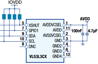
Figure 11: Smart parking with the VL53L3CX
- 5.9 Presence Sensing System Using the VL53L0X ToF Ranging Sensor
Human presence detection is a vital need in a growing number of applications, ranging from computer peripherals, domestic appliances, and personal electronics to building access management, security, and healthcare systems. New applications must ensure the seamless interactions of users with associated systems and services.
This system is based on the VL53L0X FlightSense ToF ranging sensor, which enables actual distance measurements to the nearest millimeter, independent of surface reflectivity. Human sensing also comprises TMOS thermal sensing technologies. The two technologies match and enable accurate presence detection in the immediate neighborhood. Figure 12 illustrates a system block diagram using the VL53L0X.
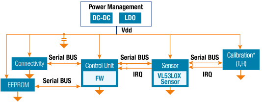
Figure 12: Human Presence Sensing with the VL53L0X sensor
- 5.10 2D LIDAR Using Multiple ST VL53L1X Time-of-Flight Sensors
This 2D LiDAR is an application example based on nine VL53L1X long-distance ranging ToF sensors. It allows a simple depth map of the environment to be created with a 180° FoV. This system can be made using the VL53L1X ULD API (ultra-lite driver application programming interface), as well as a set of C functions controlling one or multiple VL53L1X sensors. (Existing software has been created by ST Microelectronics and available on st.com) This 2D LIDAR application is an example of how to manage numerous sensors.
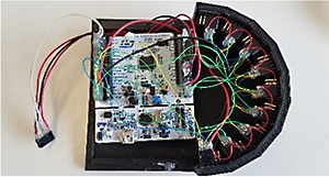
Figure 13: 2D LIDAR with Multiple VL53L1X Sensors (Source: STSW-IMG017)
The complete system is made using the P-NUCLEO-53L1A1 combined with the STM32F401RE NUCLEO board and the X-NUCLEO-53L1A1 expansion board, as shown in figure 13. The nine sensors are built on VL53L1X breakout boards and share identical I2C interface, power, and ground. The reset pin of each sensor connects to an allocated GPIO pin on the host.
Each sensor among the nine covers an FoV of 20° to cover the 180° FoV of the LIDAR. The program written into each sensor makes it range sequentially through 13 overlapping ROIs. This balances the 20° FoV of nine sensors with better resolution, and even the position of thin objects is reported.
6. Glossary
- Ambient light: The light already present in a scene before any additional lighting is added
- CMOS: Complementary Metal Oxide Semiconductor
- Density: The Angular step size between sample points and can differ horizontally and vertically
- Depth Accuracy: The difference between the measured range and the actual range
- Field-of-View (FoV): The angular area of the perceivable field of a sensor
- GPIO: General Purpose Input-Output
- GUI: Graphical User Interface
- I2C bus: Communication lines based on the Inter-Integrated Circuit protocol
- Minimum and Maximum Range of ToF sensor: this defines distances perceivable to the sensor, and can vary by object material, reflectivity, brightness, etc.
- Photon: the lowest discrete amount of electromagnetic radiation, and the basic unit of all light
- Region of Interest (ROI): The sensing array is called the Region of Interest
- Resolution: This is generally expressed as the multiplication of FoV and Density
*Trademark. STMicroelectronics is a trademark of STMicroelectronics Inc. Other logos, product and/or company names may be trademarks of their respective owners.
Test Your Knowledge
Sensors V
Are you ready to demonstrate your Time of Flight Sensors knowledge? Then take this 15-question quiz to see how much you've learned.
To earn the Sensors V Badge, read through the learning module, attain 100% on the Quiz, leave us some feedback in the comments section, and give the learning module a star rating.
Top Comments