Electric motors, and their associated drive controllers, are an integral part of our lives today. They come in different sizes, capacities, and are found in applications such as home ceiling fans, kitchen appliances, clocks, vehicles, and a wide variety of innovative IoT, smart, and industrial devices. This learning module will take you through the fundamentals of electric motors, various types of DC motors, and the electronic circuits required to drive them.
Related Components & Dev Boards | Test Your Knowledge
2. Objectives
Upon completion of this module, you will be able to:
- Explain the basic operation of an electric motor
- Describe the differences between a Brushed DC motor, Brushless DC motor, Stepper motor, and Servomotor
- Discuss the components and operation of a DC Drive Control System
- Analyze motor driver circuits
- List some practical tips for working with motors
3. DC Motor Basics
An electric motor is a machine that converts electrical energy into mechanical energy using electromagnetic principles. Electric motors produce linear (push-pull) or rotational (torque) force. Linear motors are commonly used in traction or material handling applications, while rotary motors are used in common applications such as fans, blowers, and pumps.
The two broad categories of electric motors are AC motors and DC motors, based upon their input power (electrical energy). This module will focus on DC motors. The main types of DC motors that will be covered in this module include brushed, brushless, stepper, and servomotors.
The main components of a basic brushed DC motor include:
Stator: The stator is the stationary part of an electric motor. It is made up of an electromagnetic circuit constructed by either windings or permanent magnets, as shown in Figure 1. The stator core is constructed using many thin laminated metal sheets. Lamination is used to reduce energy losses and eddy currents.
Rotor: In an electric motor the moving part is called a rotor. It turns the shaft to deliver the mechanical power. The rotor usually has conductors laid into it (armature) that carry current, but some motor types use permanent magnets (See Brushless DC Motors, Section 4.2) The rotor’s magnetic field interacts with the magnetic field of the stator to generate the torque that turns the shaft.
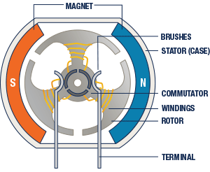
Figure 1: Cross-section of a Brushed DC Motor
Bearings: The rotor is supported by bearings, which allow the rotor to turn on its axis. The bearings are in turn supported by the motor housing (sometimes called end bells). The motor shaft extends through the bearings to outside of the motor, where the load can be connected directly or via some type of transmission or linkage.
Brushes: Brushes are employed to connect electric current from the voltage source to armature through the commutator. They are held by brush holders in a fixed position. An adjustable spring inside the brush holder exerts a constant pressure on the brushes in order to maintain a proper contact between the brush and the commutator. The brushes are connected to the armature terminals of the motor. The material used in the brush is normally carbon or carbon-graphite.
Commutator: Unique to a DC motor, the commutator is a bridge between the armature winding and a voltage source. It consists of contact bars with gaps between them, fixed on the rotating shaft of the motor and connected to the end coils of the armature winding. As the shaft rotates, the brushes pass over the gaps in the commutator, so the supplied electrical voltage switches commutator segments, which in turn switches the electrical polarity of the armature coils thereby reversing the flow of current in the armature winding so that the motor continuously rotates in one direction only.
4. Types of DC Motors
DC motors are broadly classified into four different categories:
- Brushed DC motors
- Brushless DC Motors (BLDC)
- Servomotors
- Stepper motors
4.1 Brushed DC Motors
Brushed DC motors utilize a current carrying armature which is connected to the DC supply through the commutator segments and brushes. Another set of windings or permanent magnets, outside of the rotor, are mounted on the motor’s stationary part, called the stator. The rotor and stator are assembled such that there is an air gap between them. The stator magnets develop alternate North and South poles. When electric power is applied to the armature coil, the rotor’s magnetic field starts to interact with stator’s magnetic field and produces torque to make the motor rotate.
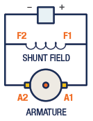
Figure 2: Shunt-Wound DC Motor
There are four types of brushed DC motors:
Shunt Wound DC Motor: Shunt-wound DC motors have a separate field winding and armature winding. With constant armature voltage and constant field excitation, the shunt-wound motor offers relatively flat speed-torque characteristics. DC shunt motors have the ability to self-regulate their speed, and are also known as constant speed motors.
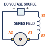
Figure 3: Series-Wound DC Motor
Series Wound DC Motor: The series-wound DC motor has the field connected in series with the armature. Series motors offer high starting torque yet have poor speed regulation. Due to their high starting or breakaway torque, they are used for starting motors for large mechanical loads in industrial applications.
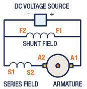
Figure 4: Compound Wound Series DC Motor
Compound Wound DC Motor: The compound-wound DC motor is a combination of both series and shunt wound DC motors. The compound-wound motor offers a combination of good starting torque and speed stability.

Figure 5: Compound Wound Series DC Motor
Permanent Magnet DC Motor: The permanent magnet motor has an armature with commutator and brushes. Permanent magnets replace the stator field windings. This type of motor has excellent starting torque, with good speed regulation. PMDC motors offer a compact size, wide operating speed range, and high torque at low speed. They are often used in battery powered devices, power tools, and medical equipment.
Operating Modes
DC motors can be operated in one or more nodes:
- Motoring
- Regenerative braking
- Four quadrants
Motoring Mode: A chopper circuit can be used to control the armature voltage of a DC motor. A MOSFET is used to drive armature current and it operates in one quadrant if the back EMF is less than the supply voltage. When the armature and field current are both positive, the motor develops torque to meet the load demand.
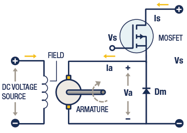
Figure 6: Motoring Mode
Armature voltage depends on the source voltage and ON / OFF time period of the MOSFET. The relationship between the armature voltage and source voltage is given below:
Va = K Vs
Where Va is the Average Armature Voltage, K is the duty cycle of the MOSFET gate pulse (Ton/[Ton+Toff]), and Vs is the DC source voltage.
Regenerative Braking Mode: In the regenerative braking mode of operation, energy is returned to the source when the motor is driven by the stored mechanical energy. It is operated as a one quadrant drive, and the motor acts as a generator. The armature of a separately excited motor is rotating due to the inertia of the motor, and if the MOSFET is switched on, the armature current rises due to the short-circuiting of the motor terminals. If the MOSFET is turned off, diode Dm would be turned on and the energy stored in the armature circuit would be transferred to the voltage source. The generated voltage across the MOSFET is:
Vch = (1-K) Vs

Figure 7: Regenerative Braking Mode
The voltage generated by the motor is given below as:
Where Rm is the Average Armature Voltage, K is the duty cycle of the MOSFET gate pulse (Ton/[Ton+Toff]), and Vs is the DC source voltage.
Four Quadrant Mode: The figure 8 shows the all quadrant operation of a DC motor.
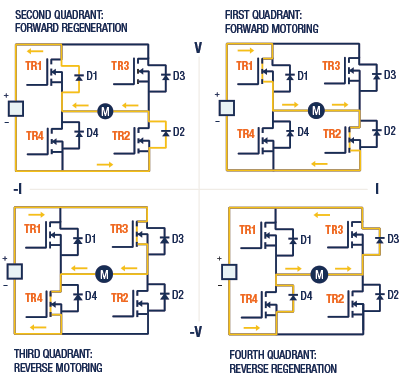
Figure 8: Four Quadrant chopper connection diagram
- First quadrant: During the first quadrant, the armature voltage and armature current are positive and the motor rotates in the forward direction. When MOSFET’s Tr1 and Tr2 are turned on together, the supply voltage appears across the motor terminals and the armature current rises. When Tr1 is turned off and Tr2 is still turned on, the armature current decays through Tr2 and D4. Alternatively, both Tr1 and Tr2 can be turned off, while the armature current is forced to decay through D3 and D4.
- Second quadrant: In the second quadrant, the motor acts as a generator and the armature voltage is positive and the armature current is negative. MOSFET’s Tr1, Tr2, and Tr3 are turned off. When Tr4 is turned on, the armature current, which rises, flows through Tr4 and D2. When Tr4 is off, the motor is acting as a generator, the motor kinetic energy is converted to a voltage and that voltage returns to the supply through D1 and D2.
- Third quadrant: During the third quadrant, the armature voltage and armature current are negative and the motor rotates in reverse direction. When Tr3 and Tr4 are turned on together, the armature current rises and flows in the reverse direction. When Tr3 is turned off and tr4 is turned on, the armature current falls through Tr4 and D2. Alternatively, both Tr3 and Tr4 can be turned off, while forcing the armature current to decay through D1 and D2.
- Fourth quadrant: In the fourth quadrant, the motor acts as a generator. In this quadrant, the armature voltage is negative and the armature current is positive. The MOSFET’s Tr1, Tr3, and Tr4 are off. Only Tr2 is turned on; the armature current rises through Tr2 and D4. If MOSFET Tr2 is turned off the armature current falls, and the motor returns energy to the supply through D3 and D4.
Torque-Speed Characteristics
A motor must develop enough torque to start a load and to keep it rotating under normal conditions. The equation for torque developed in a DC motor can be derived as follows:
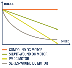
Figure 9: Torque-speed characteristics of brushed DC motors.
Where Torque T is a function of force and the distance, K is a constant depending on coil geometry (length, area, and distance), φ is the total flux produced by the field/pole measured in Webers, and Ia is the current flowing in the armature winding.
4.2 Brushless DC Motors
Brushless DC motors (BLDC) are a type of synchronous motor where the magnetic field generated by the stator and the magnetic field generated by the rotor are at the same frequency. They are also known as electrically commutated motors. The commutation relies on the feedback of the rotor position to decide when to energize the corresponding switches in the controller to generate a large amount of torque. The easiest way to accurately detect the rotor position is to use a position sensor. Most BLDC motors have Hall sensors embedded into the stator on the non-driving end of the motor.
Compared to brushed DC motors, BLDC motors have many advantages, including:
- Higher efficiency
- Lower acoustic noise
- Smaller and lighter
- Greater dynamic response
- Motoring
- Improved speed versus torque characteristics
- Higher speed range
- Longer expected usable life
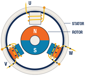
Figure 10: Cross section of a three-phase BLDC motor
A BLDC motor is built with a permanent magnet rotor, a stator winding, and position sensing system. There are two types of stator windings, Trapezoidal and Sinusoidal, which indicate the shape of the back-emf signal. The shape of the back-emf is determined by the type of coil connection and the distance of the air gap. A sinusoidal motor produces smoother electromagnetic torque than a trapezoidal motor. The position sensor is made up of a Hall Effect sensor or in some cases an optical encoder to sense the absolute position of the rotor.
The three main types of BLDC motors are: single phase, two-phase, and three-phase. The three-phase BLDC motors are commonly utilized in appliances, automotive, consumer, and industrial applications.

Figure 11: Three-phase BLDC motor circuit diagram. Visit the Related Components and Dev Boards to learn more about MOSFET BTN8982.)
Theory of Operation: BLDC Motor operation is based on the attraction or repulsion between magnetic poles. A controller acquires information from the position sensor and processes it through the programmed commands in order to drive the motor. The control circuits handle very low current to turn on the power semiconductor devices (MOSFET or IGBT), which switch on the right stator winding at the correct time and in the right sequence, based on the information received from the controller and the position sensors.
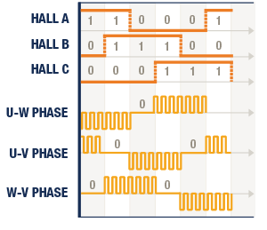
Figure 12: BLDC motor working in 6 steps
A standard 3-phase inverter power circuit is used to drive a 3-phase BLDC motor, as shown in figure 11. Inside the stator, three hall ICs are arranged as magnetic elements so that the phase difference of the output signal from each hall IC will be 120 degrees for every rotation of the rotor. The stator coil has a star configuration with three-phase U, V, and W. These end terminals are connected to the three-phase inverter, which generates a three-phase AC voltage from fixed DC voltage by turning ON/OFF in the sequence shown in Figure 12. The process starts when current flows through one of the three stator windings and generates a magnetic pole that attracts the closest permanent magnet of the opposite pole. The rotor will rotate if the current shifts to an adjacent winding. By sequentially charging each winding, the rotor will follow the rotating magnetic field.
Instead of using a mechanical commutator and brush assembly for commutation on brushed DC motors, BLDC motors use electronic commutation via a controller that repeatedly turns on the appropriate phase windings in order to maintain the motor's rotation. Table 1 shows the commutation switching sequence of the Hall Sensors and each of the phase windings of a BLDC motor. In each commutation cycle, two of the three phase windings will be energized in order to rotate the motor's rotor, with each step causing a 60 degree rotation. Six steps complete one 360 degree cycle. As mentioned previously, to accomplish the commutation, Hall sensors are used in each phase winding for determining the rotor's angular position.
| Sequence | Hall A | Hall B | Hall C | Tr1 | Tr2 | Tr3 | Tr4 | Tr5 | Tr6 |
| 1 | 0 | 0 | 1 | ON | OFF | OFF | ON | OFF | OFF |
| 2 | 1 | 0 | 1 | ON | OFF | OFF | OFF | OFF | ON |
| 3 | 1 | 0 | 0 | OFF | OFF | ON | OFF | OFF | ON |
| 4 | 1 | 1 | 0 | OFF | ON | ON | OFF | OFF | OFF |
| 5 | 0 | 1 | 0 | OFF | ON | OFF | OFF | ON | OFF |
| 6 | 0 | 1 | 1 | OFF | OFF | OFF | ON | ON | OFF |
Table 1: Commutation switching sequence for a three-phase BLDC motor
4.3 DC Servo Motor
A servo motor is a linear or rotary actuator that provides fast precision position control for closed-loop control applications. It is made up of an electric motor which runs through a servo mechanism.
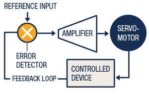
Figure 13: Basic Block diagram of a Servo motor controller
Servo Mechanism: Servo motors consist of three parts: controller, servo amplifier, and feedback system. It’s a closed-loop system to control motion and the final position of the shaft. This system is controlled by a feedback signal and reference input. The reference input signal is compared with the feedback signal and produces an error signal, which is available at the output of the error detector. This is followed by a compensator circuit and servo amplifier that produces enough drive output to turn the shaft of the motor to the desired position.
DC Servo Motor System: A DC servo motor system consists of a DC motor, driver circuit, gearbox, and feedback system. The motor which is used as a DC servo motor generally has a separate DC source to the field winding & armature winding. The control can be achieved either by controlling the armature current or field current.
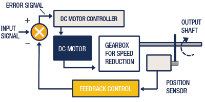
Figure 14: DC servo motor controller block diagram
The DC motor gets power from an external source or a motor drive and runs at high speed with low torque. The gearbox and shaft assembly are connected to the DC motor shaft. The reference input signal is set to the value corresponding to the desired output. The feedback (position) sensor senses the output position of the shaft and feeds the measured values to the feedback control. The feedback control circuit accordingly decodes the signals from the position sensor. The comparator compares actual input signal for the motor with the desired position of the motor shaft and produces an error signal used by the DC motor controller to drive the motor to the required position.
4.4 Stepper Motors
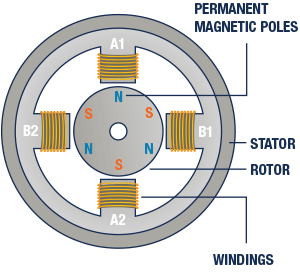
Figure 15: Cross section of a Stepper Motor
Depending upon the application, stepper motors are a good replacement for servo motors. They have greater torque at low speeds, good holding torque and are relatively low cost. Steppers consist of a stator and rotor. Their rotors rotate in discrete step increments. The stator is made up of soft iron wrapped with multiple windings, called electromagnets, and the rotor is made of a permanent magnet without coils. The arrangement of the stator electromagnets and the rotor permanent magnets in a simple stepper motor is shown in Figure15.
The two main types of stepper motors are:
- Permanent magnet: In a permanent magnet type, the rotor is a permanent magnet with a number of poles; the excitation windings are in the stator.
- Variable reluctance type: The rotor of a variable reluctance type motor is a cylindrical structure with a number of projected teeth; the excitation windings are in the stator.

Figure 16: Stepper motor rotor direction
The stepper motor control allows the flow of current through the stator windings. As the current starts flowing through the selected winding, an electromagnet pair is created and attracts the rotor’s permanent magnet and aligns with it. This results in rotation of the permanent magnet. When the windings are excited in the sequence A1-B1-A2-B2 the rotor will be driven in a clockwise direction. If we reverse the sequence A1-B2-A2-B1, the rotor will be driven in a counterclockwise direction.
A Stepper motor driver is needed to drive the stator current. The main function of the driver circuit is to change the current and flux direction in the phase windings by driving a controllable amount of current through the windings. The direction change is done by changing the current direction, and this may be done in two different ways:
- Unipolar Drive: A stator winding has three leads each at the end and one in the middle. Only half of the winding is used in motor operation at any instant of time. To change the direction of rotation, end leads are switched and the current flows in the chosen direction.
- Bipolar Drive: In a bipolar drive, winding current flows in both directions. To change stator coil polarity, all four switches are needed in the form of an H-bridge. The bipolar drive method requires one winding per phase. The motor winding is fully energized by turning on one set of the switching transistors.
Stepping Modes
The stepper motor can be operated in three different stepping modes:
- Full-step
- Half-step
- Micro-step
Full-Step
The unipolar full step excitation mode is achieved by energizing both windings while reversing the current alternately. Essentially one digital input from the driver is equivalent to one step. Full step sequence is shown in Table 2.
| Steps | A1 | B1 | A2 | B2 |
| 1 | ON | OFF | OFF | ON |
| 2 | ON | ON | OFF | OFF |
| 3 | OFF | ON | ON | OFF |
| 4 | OFF | OFF | ON | ON |
Table 2: Unipolar Stepper motor Full step sequence
The bipolar stepper motor driver turns on the switches one after another in the switching sequence, shown in Table 3.
| Steps | A1 | B1 | A2 | B2 |
| 1 | ON | OFF | OFF | OFF |
| 2 | OFF | ON | OFF | OFF |
| 3 | OFF | OFF | ON | OFF |
| 4 | OFF | OFF | OFF | ON |
Table 3: Bipolar Stepper motor step sequence
Half-Step
Another switching sequence for the stepper motor is called an eight-step or half-step sequence. In the half step mode, the drive alternates between two phases ON and a single phase ON. The Half step sequence is shown in table 4.
| Steps | A1 | B1 | A2 | B2 |
| 1 | ON | OFF | OFF | OFF |
| 2 | ON | ON | OFF | OFF |
| 3 | OFF | ON | OFF | OFF |
| 4 | OFF | ON | ON | OFF |
| 5 | OFF | OFF | ON | OFF |
| 6 | OFF | OFF | ON | ON |
| 7 | OFF | OFF | OFF | ON |
| 8 | ON | OFF | OFF | ON |
Table 4: Stepper motor half step sequence
In this mode, the resolution of the motor is doubled because the rotor moves in half steps. This means that a 200-step motor, which has a resolution of 1.8°, will have a resolution of 400 steps and 0.9°. The half-step switching sequence requires a special stepper motor.
Micro-Step
The full step length of a stepper motor can be divided into smaller increments of rotor motion, known as micro steps, by partially exciting several phase windings and micro-step sequence. The micro stepper controller is a driver that sends pulses to the motor in an ideal waveform for smooth rotation. The micro step driver sends sinusoidal current to the motor. Two sinewaves that are 90 degrees out of phase is the ideal driver for smooth motor rotation.
The step length and angle through which the rotor moves for each step pulse is calculated by:
Step length = 90 °/Nr
The step angle is calculated using the formula:
θ = 360*(Ns-Nr)/ (Ns*Nr)
Where θ is Step angle in degrees, Ns represents number of stator teeth, and Nr represents the number of rotor teeth.
The micro step is typically used in applications that require accurate positioning and a fine resolution over a wide range of speed. The major disadvantage of the micro step drive is the cost of implementation, due to the need for partial excitation of the motor windings at different current levels.
Speed Torque Characteristics
The torque produced by a stepper motor depends on several factors such as step rate, drive current in the stator windings, and drive design or type. The torque versus speed relationship of a stepper motor is shown in Figure 17. The two curves are the pull-in torque and the pull-out torque curve. The pull-out region is called the slewing range.
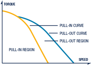
Figure 17. Torque-speed characteristics of stepper motor
The pull-out torque versus speed curve represents the maximum torque that the stepper motor can supply to a load, beyond which the motor will lose synchronism. The pull-in torque versus speed curve represents the maximum frictional load at which the stepper motor can start without failure of motion when a pulse train of the corresponding frequency is applied. The pull-in torque depends on the inertia of the load connected to the motor. The pull-in region is defined as the maximum control frequency at which the unloaded motor can start and stop without losing steps. The pull-out region is defined as the maximum frequency at which the unloaded motor can run without losing steps.
5. Motor Control Components
The essential components required to drive a motor are described in this section. Figure 18 shows a block diagram of motor controller components, including:
- Power management unit
- Protection Circuit
- Controller
- Gate driver circuit
- Motor drive
- Feedback circuit
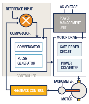
Figure 18: Motor Drive Control Block Diagram
5.1 Power Management Unit
The power management system is connected to the main voltage source and motor control unit. This AC input is converted to DC voltage by using a stepdown transformer and rectifier. This DC voltage is filtered and regulated to eliminate from the system any electrical spikes and noise.
5.2 Protection Circuits
Protection circuits, such as fuses or circuit breakers, protect the controller and driver from excessive current caused by motor overloads, ground faults, or short circuits. Short-circuit and ground-fault protection must be capable of carrying the starting current of the motor. Due to the reverse recovery process of the power devices and switching actions in the presence of circuit inductances, voltage transients occurs in the converter circuit that may cause system failure. The overcurrent device is either a fuse or a circuit breaker placed at the beginning of the circuit.
5.3 Controller
The controller consists of a user interface unit, error detector, amplifier, and pulse generator circuit.
- User interface unit: This is the input port of motor control. The user can communicate with the controller by using input devices such as a keyboard, input potentiometer, and switches to provide instructions to the controller in order to generate gate pulses for a particular application.
- Comparator: Also known as an error detector, the main function of the comparator is to produce an error signal (error voltage) by using user instruction (desired speed) and feedback signals.
- Compensator: The compensator unit is the main portion of a control circuit used to reduce the difference between the user’s expected output and the actual output. There are many types of compensator circuits, of which the PID circuit is the most popular error compensator. It consists of Proportional, Integral, and Derivative circuits to produce the voltage PID gain to reduce the error signal.
- Pulse generator circuit: The pulse generator circuit logically organizes the signal to produce gate pulses. This circuit acquires information from the compensator and compares it with an internal reference signal and produces logical HIGH and LOW signals. This circuit is also responsible for maintaining the width of the gate pulse and frequency.
Advanced controller: Microcontroller-based drives can achieve accurate speed control. The microcontroller consists of analog-to-digital (A/D) and digital-to-analog (D/A) converters, as well as a CPU that implements the control algorithm. A system clock controls the operation of the controller, synchronizing the A/D, D/A, and computing processes. The feedback signal and operator input also feed to the controller as an external input. The microcontroller monitors input signals to detect changes from connected sources such as the user interface block, the feedback circuit, and temperature sensors. Based on the status of input signals, it evaluates and organizes the control activity, and performs logical decisions according to the direction of the program flow. It produces proper PWM output signals to driver switches to run the motor at desired speed.
5.4 Protection Circuits
The gate driver circuit connects between the controller and semiconductor switches (e.g., SCR, MOSFET, IGBT). The gate driver circuit supplies the gate pulses with the necessary voltage and current to accurately and efficiently drive the MOSFETs or IGBTs so that they turn ON and OFF for particular periods. Optocoupler isolation is also provided in the gate drive circuit.
Heat is generated within the power device due to on-state and switching losses. So, the devices are usually mounted on heat sinks to transfer the heat from the device for maintaining the operating junction temperature within the specified range.
5.5 Protection Circuits
The power converter unit of the DC motor drive consists of phase controlled converters and/or dc-dc converters.

Figure 19: Single-pulse, SCR-controlled rectifier with a resistive load and firing angle delay
Phase controlled converter:
The phase controlled converter provides a variable DC output voltage from a fixed AC voltage. The output voltage can be varied by varying the delay angle ‘α’ (firing angle) of the semiconductor switches used in the converter. There are two common types of phase controller converters: single-phase converter and three-phase converters. These drives are constructed by using silicon controlled rectifier (SCR) and diodes.
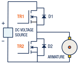
Figure 20: DC motor control circuit
DC-DC converter drives:
The DC-DC converter drive converts a fixed DC voltage to variable DC voltage. Figure 20 shows the DC motor control circuit that can be operated in two modes, power control and regenerative control.
Power control: The MOSFET Tr1 and diode D2 operate in this mode. When Tr1 is turned on, the source voltage is connected to the motor terminals. When MOSFET Tr1 is turned off, the armature current that flows through the freewheeling diode D2 decays.
Regenerative Control: MOSFET Tr2 and diode D1 operate when Tr2 is turned on; the motor acts as a generator and the armature current rises. When TR2 is turned off the motor acts as a generator, and returns energy to the supply through the regenerative diode D1.
5.6 Feedback Circuit
The feedback circuit is essential in closed-loop systems to obtain the output reference to the controller. Analog or DC tachometers are often used to provide speed feedback information for stabilization purposes, as well as for visual metering indication.
- Analog tachometers: The tachometer is mechanically connected to the motor shaft. As the shaft is turned, the sensor develops a voltage proportional to the angular velocity of the motor shaft. The output voltage shows a polarity (+ or -) which is dependent on the direction of rotation.
- Digital tachometers: A digital tachometer consists of an encoder. As the encoder's shaft is rotated, an output signal results which is proportional to the distance (i.e. angle) the shaft is rotated through. The output signal may be square waves, sinusoidal waves, or provide an absolute position.
- Feedback control circuit: The tachometer gives speed or position reference signals to the feedback circuit, which decodes the signal and converts it to a voltage or frequency for use by the controller.
6. Motor Control Tips For Makers
In this section, we want to cover some tips regarding motor control and the use of motors in projects. These are by no means a comprehensive list, but they cover some of the common ones.
Before you begin connecting a motor to a shield or development board, take a look at the specifications on the datasheet. Be mindful of voltage ranges and current capacities of the dev board/shield and the motor. Some development boards can't drive a motor directly, so you will need to use a shield, or, if you are breadboarding a design from scratch, a motor controller IC. You should make sure they are compatible.
Wiring up your project leads one to address the issue of cabling. For breadboarding your project, hook up wire is adequate. But once you are ready to build the real thing, depending on this size of the motor and the current draw, you need to make sure you select the proper wire gauge. The wrong gauge of wire can also cause problems in some cases, such as voltage drops due to the higher resistance of the wire.
Protection circuitry is an important part of building a motor control system. If you are powering your project via a battery pack, it's always a good idea to have reverse battery protection if it isn't otherwise included on a shield or development board. It can be done by putting a diode in series to the positive supply with the cathode connected to the load side. Refer to schematics of the development board and shields you are working with.
Motor overloads occur when a motor experiences excessive load on the motor shaft. The primary symptoms of motor overloads are excessive current draw, insufficient torque, and overheating. If you are driving a heavy load, rated torque is a very important parameter to keep in mind. In DC motors, operating current is proportional to torque, so exceeding rated torque is likely to lead to overheating or damage to the motor itself.
Brushed DC motors tend to require more frequent inspection than BLDC motors. Brushes should be inspected for wear, chipping and cracking. BLDC motors are very low maintenance, but from time to time it's good to take them apart and clean them. Like a brushed motor, dirt and grime can build up inside the can of a brushless DC motor.
7. Glossary
- Air gap: The spacing between the rotor and the stator meant to transmit magnetic flux for power conversion.
- Armature: A winding on the rotor shaft in a synchronous DC motor.
- Axial thrust: The unbalanced force acting parallel or along the axis of the rotor.
- Braking torque: The force applied to the brake wheel to stop the motion of the moving equipment.
- Breakaway torque: The torque needed to start moving a stationary load. It's usually higher than the torque required once a load is rotating.
- Commutation: The process of switching electric current in the phases (armature coil ends) in order to generate motion in one direction.
- Counter-electromotive force (CEMF): The voltage, or electromotive force, that pushes against the current which induces it.
- Electromotive force (EMF): The electrical intensity or pressure developed by a source of electrical energy.
- Eddy current: Loops of electrical current induced within conductors by a changing magnetic field in the conductor due to Faraday's law of induction.
- Electric Field: The space in which a charge experiences a force.
- Electric flux: The total electric line of force which flows outward from a positive charge.
- Friction torque: The torque caused by the frictional force that opposes the motion of an object.
- Full load current: The maximum current consumed by a motor when the rated load is placed on the rotor shaft.
- Full load torque: The torque required to produce the rated power of an electrical motor at full-load speed.
- Horsepower: A unit of power. Horsepower = Force x Distance/Time x 33,000. (1HP =550 foot-pounds/second.)
- Lamination: The thin, steel sheets that make up the stator and rotor. Laminated sheets are used to reduce eddy current losses.
- Locked rotor current: The current drawn by the motor when the motor rotor is locked (stopped) but the full voltage is applied to the motor terminals.
- Locked rotor torque or Starting Torque: The torque developed in an electrical motor when it starts from rest or zero speed.
- Magnetic flux: The amount of magnetic field produced by a magnetic source.
- Magnetic Hysteresis: The phenomenon of lagging of flux density behind the magnetizing force in a magnetic material subjected to cycles of magnetization.
- Ramp: The acceleration (soft start) and deceleration (soft stop) time of an electric motor. The acceleration ramp is the time taken by a motor to reach set speed from its initial speed. The deceleration ramp is the time taken by a motor to stop from its current speed.
*Trademark. Infineon is a trademark of Infineon Tech. Other logos, product and/or company names may be trademarks of their respective owners.
Shop our wide range of motor control products, including Power MOSFETS, Half & Full Bridge Drivers, Motor Controller ICs, and associated development boards. Shop Now
Test Your Knowledge
Motor Control I
Are you ready to demonstrate your Motor Drive Control Essentials knowledge? Then take a quick 15-question, multiple-choice quiz to see how much you've learned from this Essentials of Motor Drive Control.
To earn the Essentials Motor Drive Control 1 Badge, read through the Motor Drive Control for Makers module, attain 100% in the quiz, and leave a feedback in the comments section below.



Top Comments