

.jpg)

 Imagine a six‑axis industrial robot arm mid‑cycle on a factory floor. The power goes off, and production grinds to a halt. Once power is restored, the controller faces a critical challenge that must be resolved before production can resume: Where exactly is each joint right now?
With a conventional rotary encoder, the answer can be found only after a full rehoming routine is completed. The controller executes a predetermined sequence in which each axis is first moved sequentially to a reference limit before production resumes. However, such downtime costs money. In surgical robots or flight‑surface actuators, unplanned shutdowns carry even more serious consequences. Analog Devices has solved this problem at the silicon level with the ADMT4000, a pioneer single-chip True Power-On (TPO) multiturn absolute position sensor.
Why Every Existing Solution Is a Workaround
Prior to the ADMT4000, designers solving the multiturn TPO problem faced three well-known but imperfect paths.
Battery-Backed FRAM Systems: Maintain turn counts during power loss but depend on batteries or capacitors that age and require maintenance, especially in regulated or explosion-risk environments.
Wiegand Wire Energy Harvesters: Remove the battery but require additional magnetic assemblies, PCB space, and qualification effort.
Gear Reduction Mechanisms: Translate multiturn motion into single-turn sensing, but add backlash, wear, alignment sensitivity, and mechanical bulk, making them unsuitable for compact or high-cycle designs.
The ADMT4000 Approach
A 24-pin TSSOP IC runs from a single 3.3 V supply. There is no need for any battery, energy harvester, or any external magnetic assembly. Even a gearbox is superfluous. Turn counting happens passively in the physics of a nanowire spiral — drawing 0 nA at VDD = 0 V.
The Physics Behind Zero-Power Turn Counting
The ADMT4000 is built around a GMR spiral, a ferromagnetic nanowire coil that records rotations through stable magnetic domain walls. As the external magnet rotates, domain walls move through the spiral and retain their position without power. Even when VDD and VDRIVE are 0 V, drawing 0 nA, the magnetic pattern continues tracking rotations. On power-up, ADCs read the GMR resistance pattern, and the decoder instantly converts it into a turn count without movement, calibration, or host intervention. This is a physical readout of passive magnetic memory in silicon, supporting 0 to 46 turns.
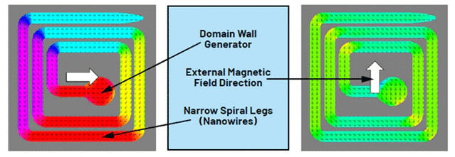
Figure 1. GMR multiturn operating principle — domain wall propagation through the ferromagnetic nanowire spiral (Source: analog.com)
Triple Sensor Architecture: From Domain Walls to 16,560° Absolute Position
Turn count alone is insufficient. To resolve where the shaft sits on a given turn, the ADMT4000 integrates two additional sensor types on the same die — forming a three-sensor architecture that requires no external components beyond the application magnet.
- GMR Turn Count Sensor: The nanowire spiral described above tracks 0–46 whole turns in a resistance-encoded domain wall pattern. It functions without power.
- AMR Angle Sensor: Two sets of anisotropic magnetoresistance (AMR) elements arranged in Wheatstone bridges, offset by 45° from each other. Output voltages are proportional to the sine and cosine of the incident magnetic field direction, delivering a resolved angle over 0°–180° of rotation with ±0.25° accuracy (typical, at 25 mT, 25°C).
- GMR Quadrant Sensor: Extends the AMR sensor's 0°–180° range to a full 360° by detecting the magnetic quadrant, removing the inherent AMR 180° ambiguity.
The digital signal processor on-chip fuses all three sensor outputs into a single value stored in the ABSANGLE register. Upper 6 bits encode whole turns in straight binary; lower 10 bits encode within-turn angle at 0.351° resolution. Result: a continuous absolute position range of more than 16,560°, delivered over SPI on every conversion cycle.
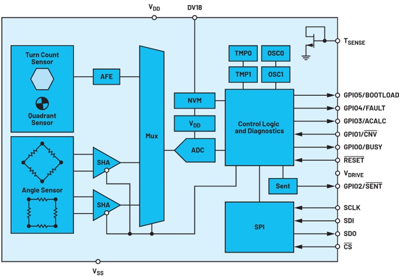
Figure 2. ADMT4000 Functional Block Diagram showing GMR turn count, AMR angle, and GMR quadrant sensor integration (Source: analog.com)
That silicon-level integration becomes especially valuable at the mechanical interface, where the only external requirement is a correctly positioned dipole magnet.
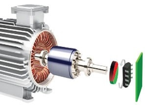
Figure 3. Typical end-of-shaft application assembly — NdFeB/SmCo dipole magnet above ADMT4000 in TSSOP package (Source: analog.com)
Electrical Specifications at a Glance
|
Parameter |
Value |
Design Significance |
|
Turn Count Range |
0 to 46 turns |
Covers most industrial and automotive multi-turn ranges |
|
Absolute Position Output |
>16,560° |
Single ABSANGLE register read — no host-side computation needed |
|
Angle Accuracy |
±0.25° (typ., 25 mT, 25°C) |
Sub-degree precision for servo and actuator closed-loop control |
|
Angle Noise (IIR filter off) |
0.25° RMS (25°C, 25 mT) |
Baseline for medium-precision applications |
|
Angle Noise (IIR filter on) |
0.03° RMS (25°C, 25 mT) |
>8× noise reduction for precision motion control |
|
Measurement Update Rate |
100 kSPS |
Sufficient for high-speed servo control loops |
|
Magnetic Field Window |
16 mT – 31 mT |
Compatible with NdFeB and SmCo end-of-shaft magnets |
|
Zero-Power Mode Current |
0 nA (VDD = 0 V, VDRIVE = 0 V) |
True battery-free passive turn counting |
|
Active Mode Current |
18–22 mA (one-shot, typ.) |
Standard 3.3 V CMOS power envelope |
|
VDD Supply |
3.0 V – 3.6 V (nom. 3.3 V) |
Single supply; compatible with standard MCU rails |
|
VDRIVE (SPI Logic) |
1.7 V – 5.5 V |
Direct interface to 1.8 V, 3.3 V, or 5 V microcontrollers |
|
Junction Temperature |
−40°C to +150°C |
Full industrial and automotive grade qualification |
|
SPI Interface |
Mode 0, up to 10 MHz SCLK |
5-bit CRC per frame (polynomial x⁵ + x² + 1, seed 0x1F) |
|
Package |
24-pin TSSOP |
Compact footprint; θJA = 73.25°C/W, θJC = 17.56°C/W |
Table 1. ADMT4000 technical specifications (Source: analog.com)
On-Chip Intelligence: Calibration, ECC, and Fault Management
Harmonic Calibration Engine: The ADMT4000 corrects 1st, 2nd, 3rd, and 8th harmonic errors caused by misalignment, magnet offset, tolerances, and shaft tilt using dedicated SPI calibration registers.
Redundant Turn Count Decoding: Primary and redundant turn count decoders run in parallel and trigger a fault if outputs differ by more than 0.5 turns.
NVM Integrity — ECC: Factory calibration and configuration data are ECC-protected with single-bit correction and double-bit detection.
SPI Data Integrity — 5-bit CRC: Each SPI frame uses 5-bit CRC to detect single and double bit errors.
Fault Register Coverage: The FAULT register monitors magnetic, decoder, NVM, ECC, voltage, and interface errors.
Magnetic Reset: A Critical Production Step
The GMR turn count sensor must be reset once. This is to be done at the point of final assembly with the installed application magnet. This injects a known domain wall pattern into the nanowire spiral, establishing a calibrated zero reference. Reset is also required if the sensor is exposed to a field exceeding BMAX, or if FAULT bits D9 or D13 are set.
Two methods are available for resetting the GMR turn count sensor. The mechanical method rotates the system magnet a minimum of 46 turns clockwise. The preferred production method applies an external field exceeding 60 mT at the 315° orientation for at least 10 µs.
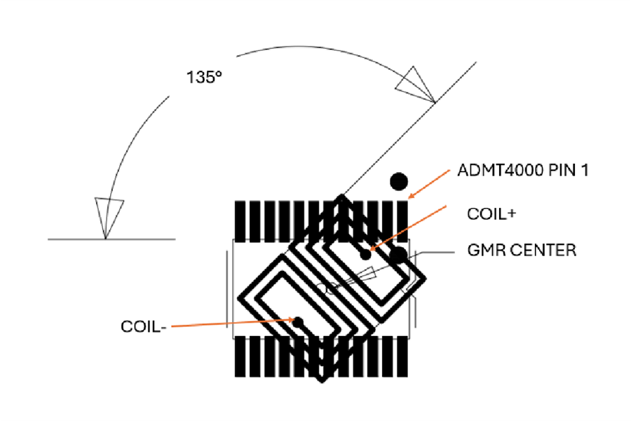
Figure 4. Embedded reset coil position and alignment relative to ADMT4000; reset pulse voltage and current waveforms (Source: analog.com)
Once the reset geometry is fixed, the production challenge shifts to delivering a clean, repeatable magnetic pulse.
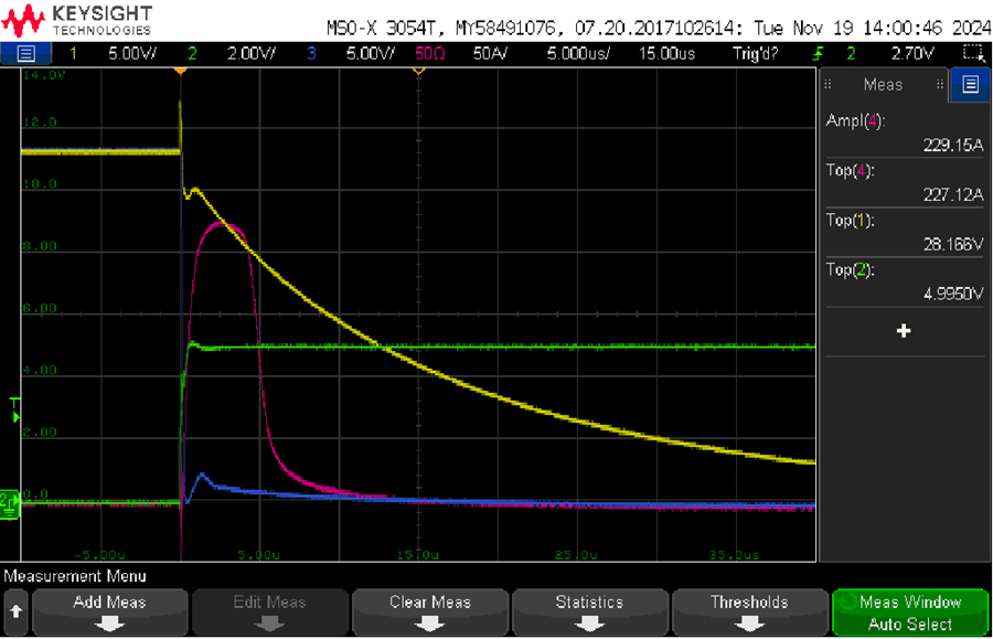
Figure 5. Reset pulse voltage and current waveforms. Yellow: voltage at drain terminal of Q1; green: voltage at gate of Q1; blue: voltage at source terminal of Q1; magenta: current pulse through coil L2. (Source: analog.com)
Application Landscape
The ADMT4000 surfaces up in a plethora of applications:
INDUSTRIAL AUTOMATION
Robotics and Cobots: Joint position tracking across power cycles eliminates rehoming after power interruption.
Wire Draw Encoders: Turn counting supports cable drums, hoists, winches, spools, and reels, including powered-off movement.
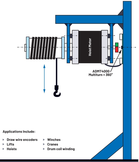
Figure 6. Wire draw encoder rotary-to-linear configuration (Source: analog.com)
AUTOMOTIVE
Steer-by-Wire / EPS: Absolute steering angle is available at ignition-on without calibration or wheel sweep.
Transmission & Parking Actuators: Position confirmation works without battery drain during key-off cycles.
MEDICAL & INDUSTRIAL
x-y Tables & Machine Tools: Power-on absolute tracking avoids startup initialization movement.
MOTOR CONTROL
Brushless DC Motors: Startup rotor position enables immediate commutation without homing. Figure 7 shows how the ADMT4000 combines zero-power turn counting with absolute angle sensing to report true multiturn position immediately after power-up—without batteries, gears, or rehoming.
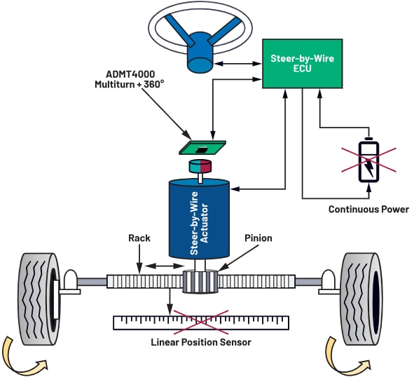
Figure 7. Steer-by-wire absolute angle application (Source: analog.com)
Conclusion - Enabling the Next Generation of Position Sensing
The ADMT4000 does not incrementally improve on existing multiturn position sensing solutions — it replaces the entire subsystem architecture. What previously required a battery or energy harvester, an FRAM chip, supporting circuitry, a maintenance schedule, and ongoing service costs now fits inside a single 24-pin TSSOP IC running from 3.3 V.
The BOM, PCB footprint, and system qualification scope shrink. The field maintenance contract disappears. Most importantly, the time-to-position after any power event collapses from a multi-axis rehoming sequence to a single SPI register read.
For any design where shaft position must be known the instant power returns, the ADMT4000 makes zero-power absolute positioning the design default rather than the engineering achievement.
For more innovative products from ADI Shop Now
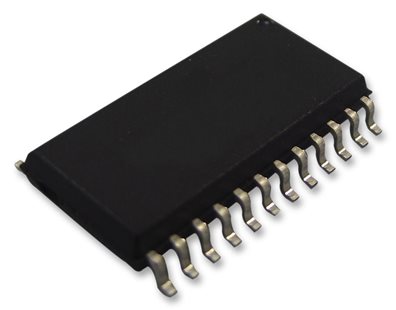
ADMT4000BRUZAB
About the Sponsor
 Every day, electronic devices are becoming smarter with greater integration. Body sensors can monitor our health. Cars can drive themselves. Networked homes can power up when needed. Analog Devices are solving engineering problems and empowering design innovation, enabling our customers to create products that shape our world. They invent highly integrated solutions that make technology seamless. Their innovative and high-performance analog and mixed-signal products and technologies make systems smaller and smarter, with enhanced security and increased energy efficiency. They channel their collective expertise to stretch the limits of technology, understand your needs, and help you get to market faster. For more information, click here.