

Table of contents

Abstract
LED show on holiday nights
Project
Hello makers and happy holidays!
Intro
I'm signing up for this activity with a project on no other theme than that of light decoration, namely a 4x4x4 cube with LEDs. So I don't think I need to explain what this project does, stay tuned because at the end you'll also find a video. 
Purpose
I know that these days there are many variations of LEDs, for example SMDs are smaller and brighter, there are addressable LEDs, i.e. individually controllable using a microcontroller, but I can't part with TH LEDs so easily so I'm trying to put them in a more favorable light through a different project-design.
Components used:
Mostly the necessary things used are:
• 64x LEDs, either 3mm or 5mm, the color is your choice;
• 16x 220Ω resistors [TH];
• 2x 2N2222 transistors;
• 4x 10kΩ resistors;
• microcontroller board (e.g. ATMega);
• PCB of course;
• some male/female pin headers;
• 1mm copper rod;
• quite a bit of manual work...and patience. 

I used both new and salvaged components that I reuse without any problems.
Design
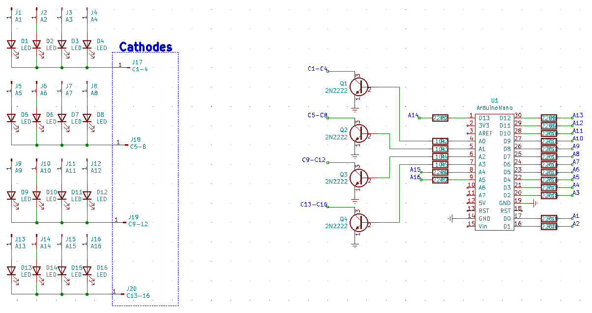
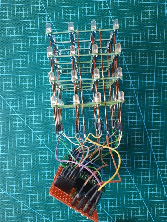
For all these LEDs to be more delightful we need an intelligent control (and the human eye which is easy to fool ), the microcontroller I use is an ATMega328P mounted on a minimal PCB that I atached to test board. I had to solder some more components and the conclusion I came to was to use pin headers. Maybe I could have used only the minimal PCB but it only resulted in an unwanted crowding of wires and solders.
I used almost all available GPIOs, as you can see in the pictures. I placed a 220Ω resistor on each GPIO that is connected to the LEDs anodes and the BJT transistors have their collectors connected to the cathodes, one for each layer.
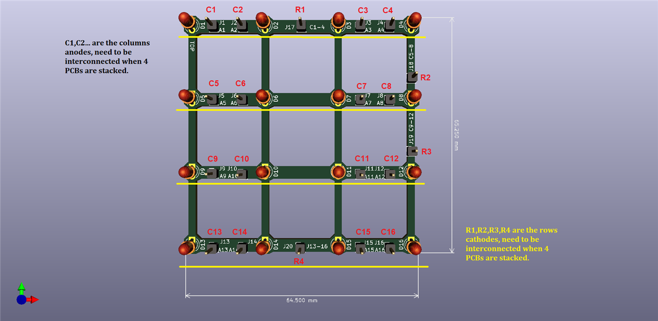
I thought I'd build a PCB for this cube to be more stable, rather than soldering LEDs on a wire, and maybe even positioning them crookedly. So, a simple PCB just for LEDs, precisely cut, dimensions ~65x65mm. We have 16 LEDs on each layer, grouped in 4. The cathodes are interconnected vertically, 4 on each layer.
| {gallery}LEDs PCB |
|---|
|
Circuit |
|
PCB with rows and columns |
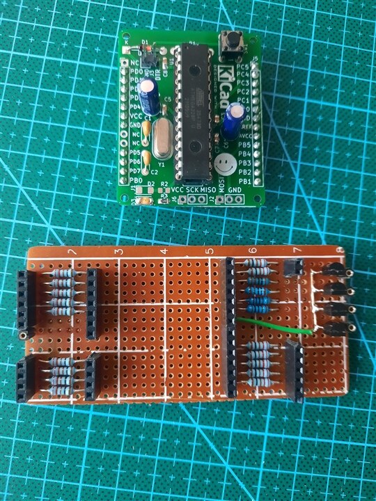
Since I made a PCB for the LEDs, another minimal one for the microcontroller, the rest of the resistors and transistors components can be assembled on a test PCB. So I proceeded to a "low cost" PCB, let's say. 
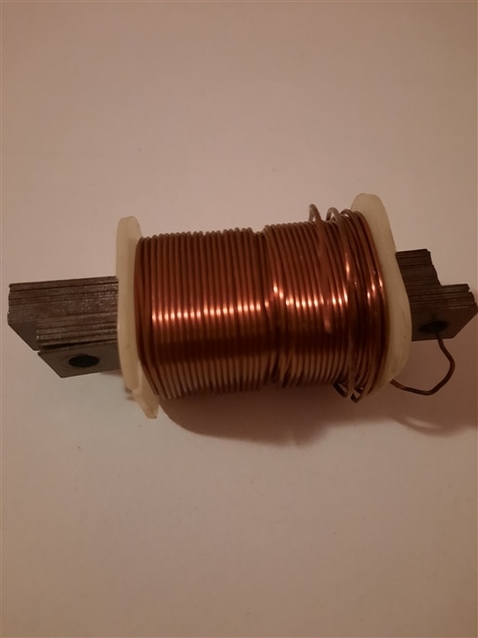
This is where the headache starts. Unfortunately, I didn't analyze this project in detail and I missed some aspects. The first would be that the copper wire I use is 1mm in diameter. The holes drilled in the PCB are about the same size, but in the end they fit. Another thing was that the copper wire has a protective outer layer of enamel (or something like that) that is quite difficult to remove but I handled it somwhow. Even so, at some point it was difficult to make correct soldering. I found a coil and cut a few segments with pliers, then removed the outer enamel little by little. One thing I try to apply as often as I can, modular assembly, I first thought about the PCB with LEDs because it is a little difficult to troubleshoot if problems arise, but at least I managed with the 20 wires soldered to the rods, I used female headers.
The layers are spaced ~20mm apart, which is enough for 5mm LEDs.
Tips for anyone who wants to do such a project: use a wire or rod that can be soldered along its entire length (without protective outer layer), it saves you a lot of manual work; position the 4 layers (PCBs) then insert all the wires through the interconnection holes. Later, you can easily space them out as you wish.
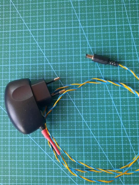
I used a single power supply, 5V, for which I had to solder the wires and the DC jack.
| {gallery}Start assembling the cube |
|---|
|
Microcontroller board + test board [top] |
|
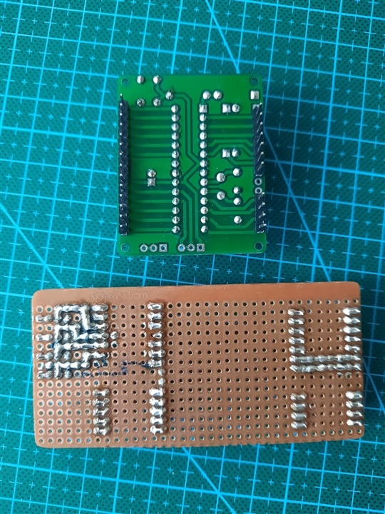
Microcontroller board + test board [bottom] |
|
Assembly 1 |
|
Assembly 2 |
|
The box 1 |
|
The box 2 |
|
The box 3 |
|
|
 Copper rods |
|
5V power supply |


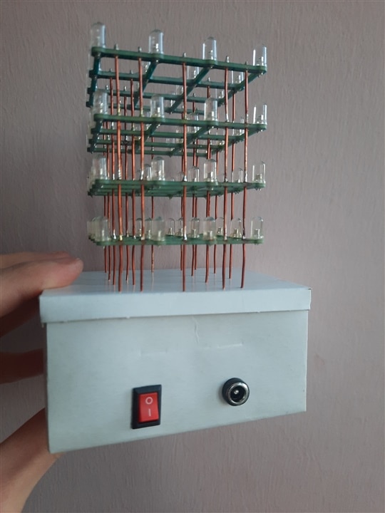

Emergency solution, the box is made of cardboard, I definitely won't keep this case, but my friend is on vacation at the moment and I can't call on him to build a proper case on the 3D printer, but he will be available next year (a long time until then ). It will be useful for me both for the layout and for proper mounting of the boards.
The program takes up almost all available memory, it is not created by me, it is open source, I took it from the internet some time ago. I can't tell you much about this it. Thanks to the author for that. 
2843.Complete program.txt
And a short video:
What do you say, is it a proper light decoration?
