

Table of contents

Abstract
The “Smart RGB Snowflake Ornament” is a custom-designed PCB shaped like a snowflake and finished with a colored silkscreen. The front side is populated with RGB LEDs to create dynamic lighting effects, while the back side houses the core electronics.
Project
Smart RGB Snowflake Ornament
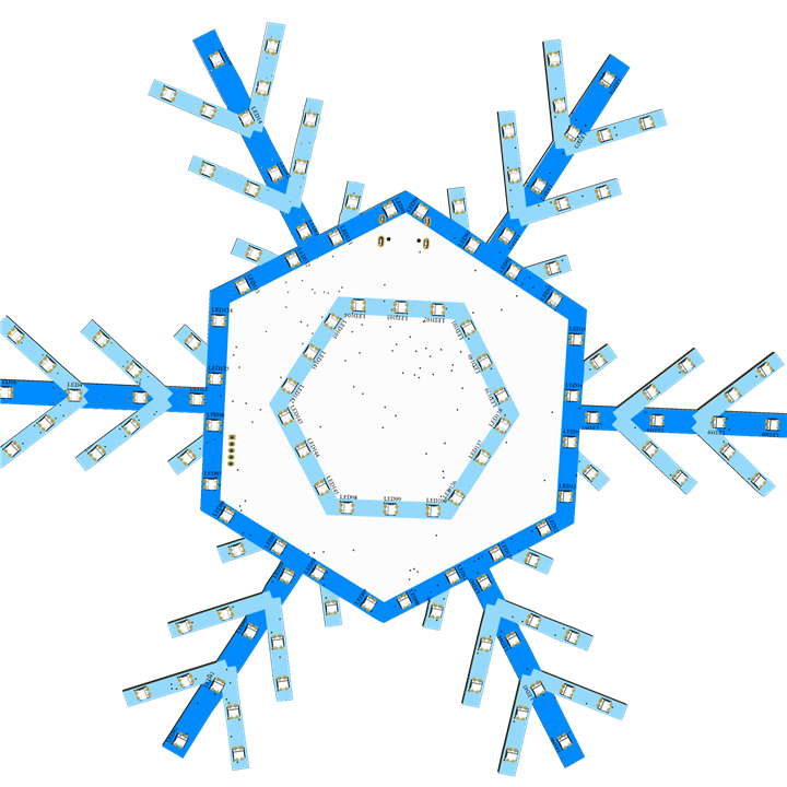
Table of Contents
Introduction
For this holiday season, I plan to build an interactive project that goes beyond a traditional decorative ornament. Instead of functioning solely as a static lighting display, the project is designed to actively engage with people around it. When human presence is detected, the ornament responds by illuminating with dynamic RGB lighting effects while simultaneously playing festive music, creating a lively and immersive experience.
The interaction is driven by a human detection mechanism, allowing the system to sense nearby movement or presence and react instantly. This transforms the ornament into a responsive element that feels alive, drawing attention and encouraging interaction rather than simply being observed. The combination of synchronized lighting and audio enhances the festive atmosphere, making the decoration more memorable and emotionally engaging.
By blending electronics, embedded control, lighting, audio playback, and sensing technology, this project showcases how modern interactive design can elevate a simple holiday ornament into a smart, experience-driven display. The goal is not only to decorate but to create moments of surprise and joy, where light and sound work together to celebrate the spirit of the season in an interactive and meaningful way.
Objective
To develop an interactive holiday ornament that combines smart RGB lighting, music playback, and human detection for an immersive festive experience.
Hardware
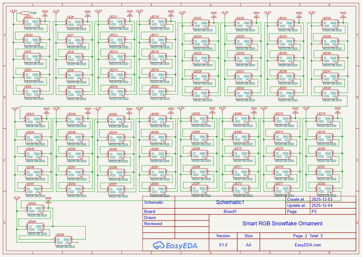
For building this project i have decided to create a PCB in a snowflake shape. The circuit is build around XIAO ESP32S#, mmWave sensor, Mp3 circuit and lots of neopixel. The design of the schematic as shown in the figure below.
The Design


The PCB view of the circuit is as shown below. The TOP view and the BOTTOM view
The Top View

The Bottom View

The Layout

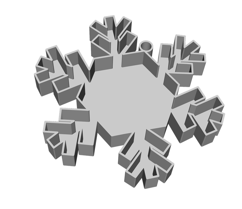
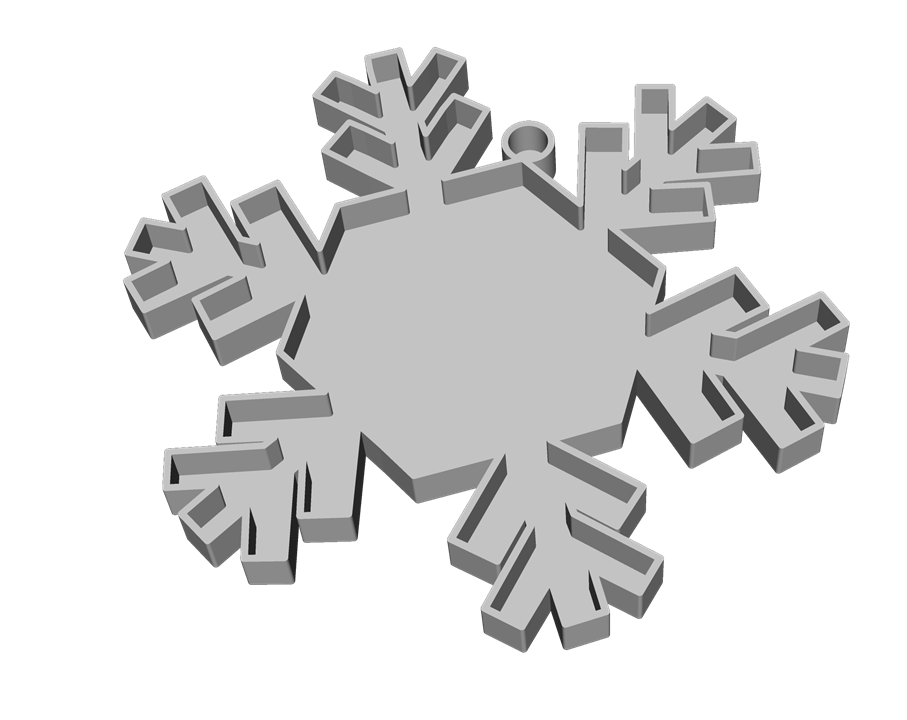
And below is the 3D view of the design


And finally, with colour silkscreen

3D Design
I have designed an enclosure for the PCB file as well. Below are the design file. The enclosure is enclosed the PCB and battery inside the


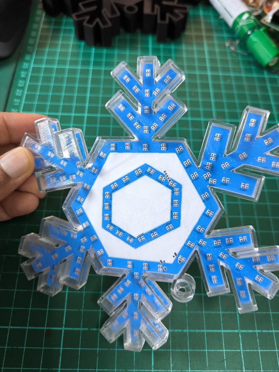
The image below shows the fabricated PCB and also the 3D printed enclosure
Top View Bottom View


The 3D printed enclosure


Software
Prior to assembling all the components to the PCB board and also waiting for some components to arrive. I have tested each of them separately. Below are the details for each of the test.
WS2812B LED
The RGB LED which i have decided to use in this project is the WS2812B 2020. Since the component which i have ordered yet to arrive. I have used the LED strip to test the code. I have used the sample code provided to test the code. The figure below shows the 2020 WS2812B LED.
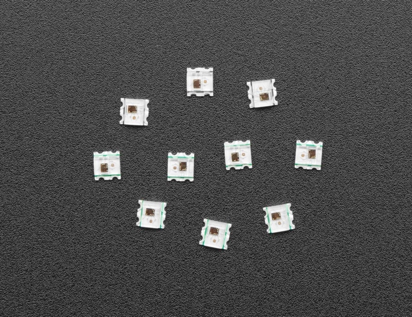
And the LED strip which i have used
And the example code which I have used is shown below
/// @file    Cylon.ino
/// @brief   An animation that moves a single LED back and forth as the entire strip changes.
///          (Larson Scanner effect)
/// @example Cylon.ino

#include <FastLED.h>

using namespace fl;

// How many leds in your strip?
#define NUM_LEDS 80

// For led chips like Neopixels, which have a data line, ground, and power, you just
// need to define DATA_PIN.  For led chipsets that are SPI based (four wires - data, clock,
// ground, and power), like the LPD8806, define both DATA_PIN and CLOCK_PIN
#define DATA_PIN 10
#define CLOCK_PIN 13

// Define the array of leds
CRGB leds[NUM_LEDS];

void setup() {
	Serial.begin(57600);
	Serial.println("resetting");
	FastLED.addLeds<WS2812,DATA_PIN,RGB>(leds,NUM_LEDS);
	FastLED.setBrightness(84);
}

void fadeall() { for(int i = 0; i < NUM_LEDS; i++) { leds[i].nscale8(250); } }

void loop() {
	static uint8_t hue = 0;
	Serial.print("x");
	// First slide the led in one direction
	for(int i = 0; i < NUM_LEDS; i++) {
		// Set the i'th led to red
		leds[i] = CHSV(hue++, 255, 255);
		// Show the leds
		FastLED.show();
		// now that we've shown the leds, reset the i'th led to black
		// leds[i] = CRGB::Black;
		fadeall();
		// Wait a little bit before we loop around and do it again
		delay(10);
	}
	Serial.print("x");

	// Now go in the other direction.
	for(int i = (NUM_LEDS)-1; i >= 0; i--) {
		// Set the i'th led to red
		leds[i] = CHSV(hue++, 255, 255);
		// Show the leds
		FastLED.show();
		// now that we've shown the leds, reset the i'th led to black
		// leds[i] = CRGB::Black;
		fadeall();
		// Wait a little bit before we loop around and do it again
		delay(10);
	}
}
The output of the LED will be as shown in the pic and video below

Interfacing
For the interfacing part i am not able to integrate or assemble them on the PCB board due to the delayed in the shipping of the components which i have ordered. I will complete the full circuit once i have received all the components.
Result & Discussion
I believe this is an interesting project to build and work on. But sadly i was unable to complete the project due to delay in the shipping of the component.