


1. Overview
This is the second instalment of my blog series following my Vacuum Pick and Place Assistant project. If you haven't seen the first part and want to get an overview of what this project is all about then I recommend you go take a look at that first. You can find Part 1 of this series here: https://www.element14.com/community/people/rachaelp/blog/2016/12/20/lab-equipment-projects-vacuum-pick-and-place-assistant-part-1
I'll be honest, I have been struggling a little with writing this as I am used to writing projects up in technical design documents or project reports and the audience for these is very different to that of a blog. I'm still fairly new to blogging and trying to find out what works and what doesn't so let me know what you think. If something was not fun to read I want to know. If something was confusing I want to know. If you really loved something I want to know that too. Basically feel free to give me your honest opinion on my blogging style as well as on the project, and if you have any questions about anything in the project please ask.
The aim of this blog is to cover the requirements capture and high level design required for building the first prototype. Now, I should point out that I have taken a fairly loose approach to design on this one. I have lots of ideas in my head and I could go about it with a formal design process to take my requirements into a detailed design, but that's not nearly as much fun as sketching out a very rough design and building and hacking a prototype until it works! 
Once I have a working prototype, I will then look at doing a more tidy design and wrap everything up into a custom PCB to be incorporated into the final unit and I'll go through some of the actual process in more detail at that point. For now lets just get on with sketching out a prototype!
2. Requirements
This instalment will cover in more detail than was covered in the overview, the requirements of the project. These will be functional requirements (i.e. what are the specific functions this project is required to perform?), physical requirements (e.g. form factor, weight, etc), electrical requirements (e.g. how is it powered, what are its external electrical interfaces, etc), and software requirements (e.g. what is required to be implemented in software that isn't already stated in other requirements). These will all be kept at a fairly high level and any detail needed for implementing the prototype will be covered within the design.

Unfortunately a typical requirements spec isn't an exciting read so instead of listing all the requirements here I am simply including a PDF file for you to read if you wish to which contains all the uniquely numbered requirements. I've numbered the requirements so I can refer back easily the each one in the design if needed and it makes it easier to ensure all requirements have been covered.
3. Design
I'm going to keep all the design detail quite high level at this point. Once I get into building and testing the prototype I will give more details on specific parts of the design that may be of interest but for now, to keep my options open for how to implement things and also to keep this blog from getting longer than necessary I will omit some of the finer details.
3.1. Vacuum Generation and Control
A simple micro-piston vacuum pump should be adequate to provide the required suction for pickup. This will cause quite a lot of vibration within the unit though so it is essential to provide adequate damping to absorb the vibration and prevent it transmitting through the chassis. It may also be necessary to add sound dampening material to the inside surfaces of the chassis to absorb motor noise.
The motor for the vacuum pump shall be normally continuously running but will be software controlled via a relay to enable the motor to be switched on / off from the software for power / noise reduction.
The control of the vacuum to the pen will be via a solenoid valve which will be controlled by the microcontroller. In addition there will be an in line pressure regulator so that the optimal vacuum pressure can be set during development. I'm also planning to add a small inline filter in case small parts like 0402 resistors accidentally get sucked up as I don't really want them going all the way through the pump and potentially damaging the piston and then firing shards of smashed up component out the other side with the potential to end up in the electronics!
For the actual vacuum pen I purchased a really cheap manual vacuum pen from eBay and removed it's manual vacuum core. It's not very well built and doesn't seal well so I will sort out these issues with it when I come to put everything together. It's nothing a hot glue gun can't solve I'm sure!  For the tip lighting I plan to run some very fine wires inside the vacuum tube to connect to an LED mounted near the tip.

As an optional add on, it may be possible to add a secondary vacuum port and allow the solenoid to switch the vacuum between ports. This may allow, with the inclusion of a suitable in-line filter, for the unit to provide vacuum fume extraction directly from the tip of a soldering iron.
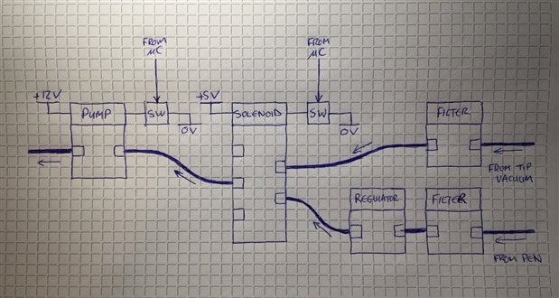
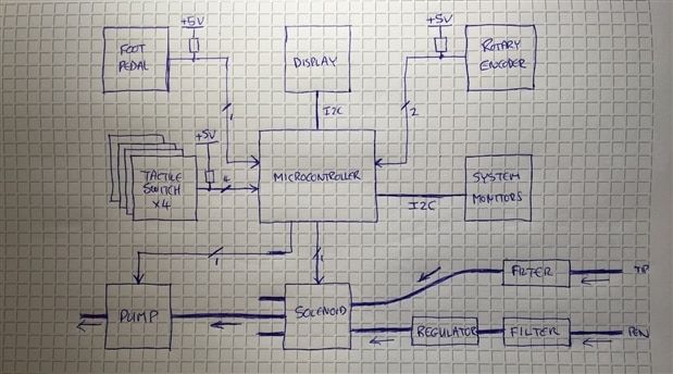
The following is a sketch of how I see the pneumatic system fitting together and interfacing with the microcontroller. You can see there are two signals from the microcontroller to control the power to the pump and the solenoid. I've omitted the actual circuits for switching the pump and the solenoid on and off for this post.
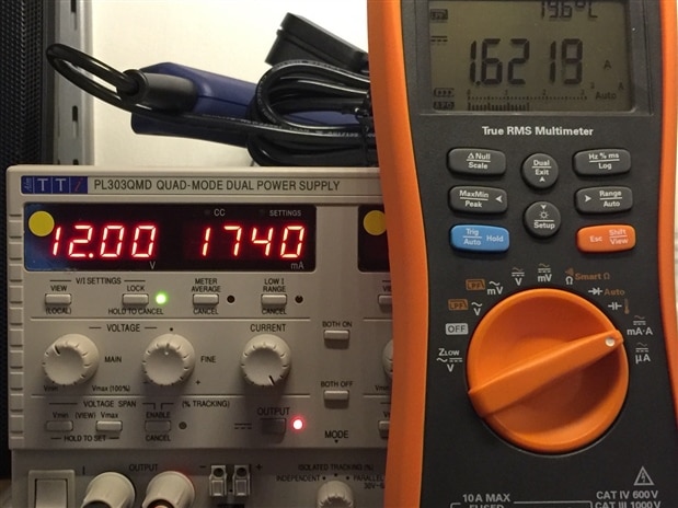
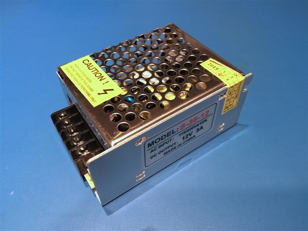
Now to an interesting update on something I discovered whilst doing a little testing on my bench earlier! The micro-piston vacuum pump I have chosen and which is pictured above is from Amazon here https://www.amazon.co.uk/gp/product/B00VQ6C72G/, and is advertised as having a rating of 12V @ <630mA. I hooked this up to my TTi PL303QMD bench power supply, set the voltage to 12V and the current limit to 1A and then powered on.


To my surprise it went into current limit and the voltage dropped sharply. So I decided to gradually up the current limit to see what happened and found that when it's running it actually takes over 1.6A. I have my Agilent U1272A in the circuit to measure the current as the ammeter built into the power supply jumps around wildly with this motor attached to it and it's impossible to get a valid reading.
I then decided to see what would happen if I dropped the voltage and it carried on working at 5V and at this voltage the current was just 850mA.
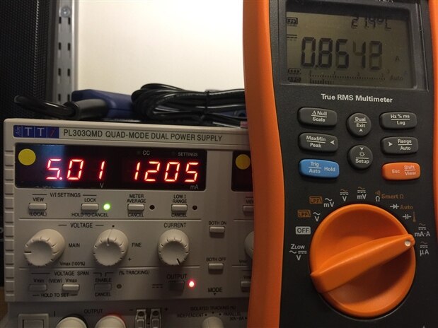
So what is going on? Is it a 12V motor and they specced the current rating incorrectly, or is it a 5V motor and they specced the voltage requirement incorrectly? Unfortunately there is absolutely no information on the motor whatsoever so I can't go and look for a spec sheet for it online. One thing to note is that when running from 12V it is very noisy and at 5V it's much more tolerable. It's easier to stall but so long as the PSU has enough current capability that its voltage output doesn't start to drop it's ok. I think I need to run some tests to see what suction levels I get and whether 5V gives adequate suction for this project. If it does it will make it so much quieter and it'll be happy days in my lab!
3.2. External Electrical Interfaces
The unit compromises the following electrical interfaces:
- External power shall be provided via AC mains.
- An RS232 interface to connect to the smart component holder / feeder. This will be used to indicate in which channel of the feeder the next component is located. Additionally this could provide an “advance” signal to a powered feeder to automatically advance a feed to the next component once the current component has been placed.
- An RS232 interface to connect to the smart laser placement position unit. This will give information to the unit to specify the exact location of the component to be placed so that the laser cross hairs can be targeted at that location. It will also allow for calibration of the initial position and board extents using the buttons on the main unit in a special setup mode prior to commencing placement.
- Power to the vacuum pen to power the tip light. This can be thin wires fed through the vacuum tube and up to the tip as they are only required to carry a few tens of mA of current to power the LED.
- The system will be programmable (i.e. Firmware running on the microcontroller) via a USB port.
- The system will have a single Ethernet adapter to connect to a network which is required for normal operation.
- The system will have provision for connecting up an external foot switch which will be used for controlling the vacuum to the pen.
3.3. Microcontroller Core
The microcontroller for this project doesn’t need a lot of processing power but it does need to provide a number of external interfaces:
- 2 x I2C interfaces (for display and internal monitors).
- 2 x Serial interfaces (for the external add-ons).
- 6 x GPIO configured as inputs for push button switches and the foot pedal.
- 2 x GPIO configured as inputs for the rotary encoder.
- 2 x GPIO configured as outputs to control the motor relay and vacuum solenoid.
- 1 x Ethernet port for operating data.
- 1 x USB port for firmware upload.
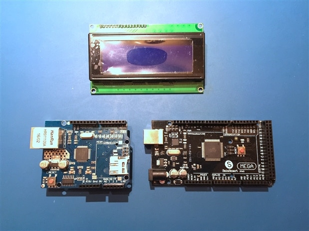
To simplify the initial prototype development the microcontroller core shall be implemented using an Arduino Mega 2560. To provide the Ethernet connection I plan to use an Ethernet shield with the Arduino. All the other IO will be connected up to GPIO pins on the Arduino that aren't used by the Ethernet shield. One interesting thing about the Ethernet shield is it also contains a microSD card slot. I could possibly utilise this to enable data files for the Pick and Place to be hosted locally so the unit can be used without a network available which would make it more portable. Obviously in the prototype configuration the microSD card slot is going to be a little inaccessible inside the chassis but for the final version I can locate an SD card slot so it's accessible from the front.
Once the design has been proven and is working a custom controller board incorporating all the electronics within the unit shall be produced. This will be based on the same ATMega2560 used on the Arduino so it will be able to be configured using the same firmware. Details of moving the design from prototype to a fully custom implementation will be covered in a follow up blog post.
3.4. Power Supplies
The power input is an AC mains supply. In the UK this is 220V-240V 50Hz but if this were to be used elsewhere then other countries have 110V-120V 60Hz supplies. It would therefore make sense to use a power supply with a universal input. These tend to have a range of approximately 90V-250V 50/60Hz.
The vacuum pump uses a 12V DC supply and can draw up to 1.6A. The LCD display, microcontroller and other logic are powered from 5V or 3.3V. These rails can be derived from the 12V rail using simple DC-DC converters. For the prototype, the Arduino will take a 12V input. 5V and 3.3V rails will still be required but the current requirements will be reduced and these will be created using off the shelf DC-DC converter boards.
It therefore makes sense for the input AC-DC power supply to provide 12V at >= 3A to supply enough power for the entire system with some headroom. Note that in light of the uncertainty about the 12V motor in the vacuum pump outlined above there may be some changes to this once I actually start putting things together and do some testing.
3.5. Front Panel
The front panel provides the display to give the user information and various knobs and buttons which, when combined with the display, will form the user interface (UI) for the project. The design of the UI will come in the software section of the project in a subsequent post. At this point I want to cover all the main topics needed to be able to put together the hardware of the project so will leave the software part of the design to another day. Given the requirements for the unit and the chassis which I have chosen which is shown in part 1 of this series, the front panel may look something like the following:
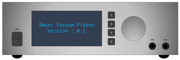
You can also see the attachments on the front at the bottom right for the vacuum tubes. The one marked PRI is the one intended for the pick up pen. The AUX attachment is to allow for a fume hose to be attached to a soldering iron to take the fumes close to the tip. This is listed as one of my add-on goals to potentially be covered in a future blog but I have added it now to I can provision for it in the front panel so I don't need to get anything remade in future.
3.6. Rear Panel
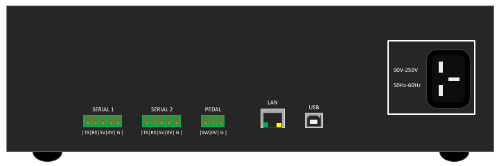
The rear panel will have a standard 3-pin IEC inlet connector for the mains power input. It will have two 5-way connectors for serial connections to external equipment. The connectors shall have to following pins: Tx, Rx, +5V, 0V, GND (for a cable shield). Standard 5-way 3.81mm or 5.08mm terminal block style connectors would be ideal for this. Finally it will have a 3-way connector to connect the foot pedal. The connector shall have the following pins: SW(NO), 0V, GND (for a cable shield). A standard 3-way 3.81mm or 5.08mm terminal block style connector would be ideal for this. Given the requirements for the unit and the chassis which I have chosen which is shown in part 1 of this series, the rear panel may look something like the following:
4. Summary
4.1. System Block Diagram
The following is a rough sketch of the major components of the system and how they will all connect together. Please excuse the rough hand sketches, I had tried to draw this in Microsoft PowerPoint 2016 and realised that somewhere between the 2007 and 2016 versions they have completely ruined it and made it pretty much utterly useless for anything other than cheesy presentations so I gave up and drew it by hand!
4.2. Thoughts
Now we have an idea of how things are going to work out from an electrical design perspective and we can see how the pneumatic side should work. We will only know when I have the prototype built whether this is going to work as planned. When shabaz wrote his blog for his version of this he reported that he needed a chamber to pressurise when sucking to give a quick puff of air when released to push the component off (aka. Mr Sneeze!!). Other projects I have seen online haven't needed this so I am wondering why this was needed? I am going to build up my prototype without this additional chamber for now and see how it operates and will then decide if I need to incorporate a similar scheme into this build.
How it will all hang together mechanically is all still to be decided too. There are various issues to consider, not only how it all physically mounts within the chassis, but vibration and noise from the pump, electrical connectivity, heat, etc. It'll be fun work out what all the issues are and getting it all to work.
Again, thanks for reading and let me know your thoughts in the comments!
| Smart Vacuum PnP Tool - Requirements.pdf |

Top Comments