element14 Community
element14 Community
    Register Log In
  • Site
  • Search
  • Log In Register
  • Community Hub
    Community Hub
    • What's New on element14
    • Feedback and Support
    • Benefits of Membership
    • Personal Blogs
    • Members Area
    • Achievement Levels
  • Learn
    Learn
    • Ask an Expert
    • eBooks
    • element14 presents
    • Learning Center
    • Tech Spotlight
    • STEM Academy
    • Webinars, Training and Events
    • Learning Groups
  • Technologies
    Technologies
    • 3D Printing
    • FPGA
    • Industrial Automation
    • Internet of Things
    • Power & Energy
    • Sensors
    • Technology Groups
  • Challenges & Projects
    Challenges & Projects
    • Design Challenges
    • element14 presents Projects
    • Project14
    • Arduino Projects
    • Raspberry Pi Projects
    • Project Groups
  • Products
    Products
    • Arduino
    • Avnet & Tria Boards Community
    • Dev Tools
    • Manufacturers
    • Multicomp Pro
    • Product Groups
    • Raspberry Pi
    • RoadTests & Reviews
  • About Us
    About the element14 Community
  • Store
    Store
    • Visit Your Store
    • Choose another store...
      • Europe
      •  Austria (German)
      •  Belgium (Dutch, French)
      •  Bulgaria (Bulgarian)
      •  Czech Republic (Czech)
      •  Denmark (Danish)
      •  Estonia (Estonian)
      •  Finland (Finnish)
      •  France (French)
      •  Germany (German)
      •  Hungary (Hungarian)
      •  Ireland
      •  Israel
      •  Italy (Italian)
      •  Latvia (Latvian)
      •  
      •  Lithuania (Lithuanian)
      •  Netherlands (Dutch)
      •  Norway (Norwegian)
      •  Poland (Polish)
      •  Portugal (Portuguese)
      •  Romania (Romanian)
      •  Russia (Russian)
      •  Slovakia (Slovak)
      •  Slovenia (Slovenian)
      •  Spain (Spanish)
      •  Sweden (Swedish)
      •  Switzerland(German, French)
      •  Turkey (Turkish)
      •  United Kingdom
      • Asia Pacific
      •  Australia
      •  China
      •  Hong Kong
      •  India
      •  Japan
      •  Korea (Korean)
      •  Malaysia
      •  New Zealand
      •  Philippines
      •  Singapore
      •  Taiwan
      •  Thailand (Thai)
      •  Vietnam
      • Americas
      •  Brazil (Portuguese)
      •  Canada
      •  Mexico (Spanish)
      •  United States
      Can't find the country/region you're looking for? Visit our export site or find a local distributor.
  • Translate
  • Profile
  • Settings
Arduino
  • Products
  • More
Arduino
Arduino Forum How do I add a Liquid Crystal Display to my current project
  • Blog
  • Forum
  • Documents
  • Quiz
  • Events
  • Polls
  • Files
  • Members
  • Mentions
  • Sub-Groups
  • Tags
  • More
  • Cancel
  • New
Join Arduino to participate - click to join for free!
Actions
  • Share
  • More
  • Cancel
Forum Thread Details
  • State Verified Answer
  • Replies 37 replies
  • Answers 2 answers
  • Subscribers 410 subscribers
  • Views 4120 views
  • Users 0 members are here
  • x
  • 1
  • lcd_display
  • arduino
  • 16
Related

How do I add a Liquid Crystal Display to my current project

Former Member
Former Member over 12 years ago

Hello,


I recently completed, with some assistance from Coder27, Bill Abbot, Tony, and Mark Beckett the first part of my project ( http://www.element14.com/community/thread/23967?start=0&tstart=0 )

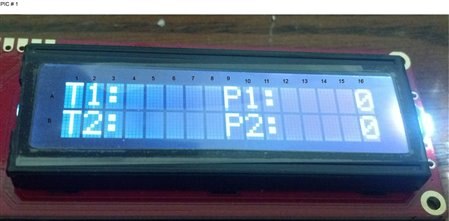
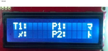
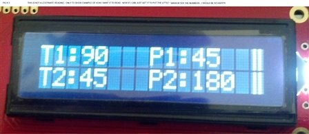
Now the second part - I am wanting to add a small 16 x 1 LCD to finish up my project (see coding below that I will be using)

I would like the LCD to simply show which direction a servo is pointing (as in degrees, such as 0°, 90°, 180°, 270°, or 360° or anywhere in between 0° to 360°)

Please be advised: I do know that arduino 1.0.4 has the LCD Scroll example, but I am sure I dont need the entire code they have.  Also, my LCD is only 16 x 1, not x 2.

Thanks,

~Anna


******** BEGINNING OF CODE *************

#include <Servo.h>


const int pan1 = 3;     // first servo

const int tilt1 = 5;    // second servo

const int pan2 = 9;     // third servo

const int tilt2 = 11;    // fourth servo


const int potpan1 = A0; // Joystick 1 Vertical signal

int val0;

const int pottilt1 = A1;   // Joystick 1 Horizontal signal

int val1;

const int potpan2 = A5;   // Joystick 1 Select signal

int val2;

const int pottilt2= A3;   // Joystick 2 Vertical signal

int val3;


int servoVal[4];        // variable to read the value from the analog pin


Servo mypan1;                                  // create servo object to control a servo

Servo mytilt1;    // create servo object to control a servo

Servo mypan2;                                  // create servo object to control a servo

Servo mytilt2;    // create servo object to control a servo


void setup()

{


  // Servo 

  mypan1.attach(pan1);  // attaches the servo

  mytilt1.attach(tilt1);  // attaches the servo

  mypan2.attach(pan2);  // attaches the servo

  mytilt2.attach(tilt2);  // attaches the servo


  // Inizialize Serial

  Serial.begin(57600);

}


void loop()

{


  outputPotentiometers();           // Read and output joystick values


  val0 = analogRead(potpan1);            // reads the value of the potentiometer (value between 0 and 1023)

  val0 = map(val0, 0, 1023, 0, 179);     // scale it to use it with the servo (value between 0 and 180)

  mypan1.write(val0);                  // sets the servo position according to the scaled value


  //Serial.print("Value of PWM 3:   ");

  //Serial.println(val0);

  //Serial.print("\t");


  val1 = analogRead(pottilt1);            // i added

  val1 = map(val1, 0, 1023, 0, 179);     // i added

  mytilt1.write(val1);                  // i added 


  //Serial.print("Value of PWM 5:   ");

  //Serial.println(val1);

  //Serial.print("\t");


  val2 = analogRead(potpan2);            // i added

  val2 = map(val2, 0, 1023, 0, 179);     // i added

  mypan2.write(val2);                  // i added


  //Serial.print("Value of PWM 6:   ");

  //Serial.println(val2);

  //Serial.print("\t");


  val3 = analogRead(pottilt2);            // i added

  val3 = map(val3, 0, 1023, 0, 179);     // i added

  mytilt2.write(val3);                  // i added


  delay(20);                                      

}


void outputPotentiometers()     // Display Joystick Values

{

  Serial.print("Pot Pan 1 on ~3:     ");

  Serial.print(analogRead(potpan1));

  Serial.print("\t");

  Serial.print("     Pot Tilt 1 on ~5:     ");

  Serial.print(analogRead(pottilt1));

  Serial.print("\t");

  Serial.print("     Pot Pan 2 on ~9:     ");

  Serial.print(analogRead(potpan2));

  Serial.print("\t");

  Serial.print("     Pot Tilt 2 on ~11:     ");

  Serial.println(analogRead(pottilt2));

  Serial.print("\t");


}


********** END OF CODE *************

  • Sign in to reply
  • Cancel

Top Replies

  • ntewinkel
    ntewinkel over 12 years ago +1 suggested
    Here's a good example to start with: http://arduino.cc/en/Tutorial/LiquidCrystal You'd have to change the setup line to be lcd.begin(16,1) for your smaller display (and assuming the lcd lib supports it…
  • mcb1
    mcb1 over 12 years ago in reply to billabott +1 verified
    Annasta Your explanation does give us some clues where your learnng lies, and how you have come to be involved, so thanks. You may have noticed that there are many people asking for help, and a lot are…
  • Former Member
    Former Member over 12 years ago in reply to billabott +1
    If I might add a bit to WATB's reply, we get all sorts of questions here, and the kind of answer you want to give differs based on the motivation for the question. If someone is asking for help with what…
  • mcb1
    0 mcb1 over 12 years ago in reply to Former Member

    Annasta


    Your comments are correct.

    The Arduino IDE comes with a set of libraries already built in.


    Adding #include <Servo.h> tells the 'sketch' to use this and the servo.cpp file (and any others it calls itself.)

    The library is just code and if you open this file, you'll probably be able to read and understand it, and the servo.cpp file.


    You can add them in any order, as long as they are above the setup.


    You will need to change

    // set the cursor to (16,1):

      lcd.setCursor(16,1);


    to 16,0 as the first line is 0 (not 1).


    Your pin change should work. The order is important, so just swap the Arduino pin, ie


    • LCD RS pin to digital pin 12
    • LCD Enable pin to digital pin 11
    • LCD D4 pin to digital pin 8
    • LCD D5 pin to digital pin 7
    • LCD D6 pin to digital pin 4
    • LCD D7 pin to digital pin 2


    You may need to adjust the scroll speed, depending on the LCD. I found the white on blue needed to be slower as you got 'ghosting' compared to the others.


    One small word of caution.

    The LCD has a controller onboard, and needs the setup from the Arduino to operate correctly.

    So if you depower the display or corrupt it, then restart the sketch to ensure it gets initialised correctly.


    Otherwise you are off to a flying start.


    mark

    • Cancel
    • Vote Up +1 Vote Down
    • Sign in to reply
    • Verify Answer
    • Cancel
  • Former Member
    0 Former Member over 12 years ago in reply to mcb1

    @ Mark -

    Thank you...going to hit the bed now...will go further tomorrow, today, later this afternoon image


    ~Anna

    • Cancel
    • Vote Up 0 Vote Down
    • Sign in to reply
    • Verify Answer
    • Cancel
  • billabott
    0 billabott over 12 years ago in reply to mcb1

    @Mark

    What is the best way to provide clean power to the LCD?  My guess is with its own BB power supply.  My concern is the EM noise the motors will be creating when moving.

    • Cancel
    • Vote Up 0 Vote Down
    • Sign in to reply
    • Verify Answer
    • Cancel
  • mcb1
    0 mcb1 over 12 years ago in reply to billabott

    William


    I haven't experienced this, mainly because I have't tried the combination of motors and LCD ...yet.


    The LCD is powered from the same 5v line as the Arduino, and the LCD's I have played with are all 5v.

    I did receive an oddball once with an extra chip and it turns out it was a 3v3 version...the chip generated the extra 1.7v to drive the crystal bits.


    Since they work using a full 5v (or 3v3) signalling, any noise is unlikely to be a major issue.


    Having said that, any time you have motors, you will get noise, and the 1000uF cap is easy, cheap insurance.

    Actually its worth adding anytime you have a wallwart type power supply.

    This will tend to stop the dip in voltage as the motor starts, which if bad enough could cause the controller chip on the LCD to reset.


    It would be nice to think that the manufacturer has also added a 0.1uF cap from each brush to the motors metal body, thereby either grounding it, or at least bypassing the higher frequency noise.


    For this project, Annasta has added the extra power supply, and made the gound go directly to the supply.

    Rerouting the ground also stops any motor current from travelling on the same path as the voltage from the pots.

    (Think of a highway for pushbikes, and a seperate highway for trucks, if at some point they made one lane common, there would be problems for the bikes).


    As an extra precaution, I would be adding a 0.1 (or even a 1-10uF) across the pot centre pin to earth.

    The pots are there to move the lights, so speed/lag isn't an issue, and it helps to ensure noise spikes are reduced, which in turn limits the motor movement causing the noise.


    For the other readers.

    The pins that the centre of the pots feed are detecting the voltage in 1024 steps or levels, which range from 0v = 0 and 5v = 1023.

    If you do the math, that means it can detect a voltage of 0.00488v (or 4.9mV) so if the voltage increases by 4.9mV the ADC reading will increase by 1.

    Any ripple/noise on these lines may affect the input reading.


    You can add hardware filtering (capacitor) or take 10 samples and average them, to help eliminate the false reading, but removing the problem at its source is always the most useful way  ... first.


    Hope this helps

    mark

    • Cancel
    • Vote Up 0 Vote Down
    • Sign in to reply
    • Verify Answer
    • Cancel
  • billabott
    0 billabott over 12 years ago

    @everyone

    An opinion poll: 

    Should one use a stripboard ($2.00) or do-it-yourself custom arduino shield ($20.00) for the finished project?

    • Cancel
    • Vote Up 0 Vote Down
    • Sign in to reply
    • Verify Answer
    • Cancel
  • billabott
    0 billabott over 12 years ago in reply to mcb1

    @mark

    Does using LCD D7 pin to digital pin 2 (TX) preclude the use of the serial monitor?

    • Cancel
    • Vote Up 0 Vote Down
    • Sign in to reply
    • Verify Answer
    • Cancel
  • mcb1
    0 mcb1 over 12 years ago in reply to billabott

    William

    Serial uses pins 0 an 1.


    Reference http://www.element14.com/community/thread/21999


    Mark

    • Cancel
    • Vote Up 0 Vote Down
    • Sign in to reply
    • Verify Answer
    • Cancel
  • mcb1
    0 mcb1 over 12 years ago in reply to billabott

    William

    In NZ we are fortunate to have Freetronics (Australia) make a much cheaper version at NZ$5.

    It is available in several outlets, and are very handy (along with one of their offerings that includes prototype area)

    http://www.freetronics.com/collections/arduino/products/eleven


    Perhaps we should be asking E14 for some cheaper alternatives ......


    These are AUS$ (but fortunately they are the same as the USD ...at the moment)

    http://www.freetronics.com/collections/protoshields


    Distributors

    http://www.freetronics.com/pages/freetronics-resellers


    Terry King (big Arduino supporter) has this

    http://yourduino.com/sunshop2/index.php?l=product_detail&p=96

    with headers

    http://yourduino.com/sunshop2/index.php?l=product_detail&p=220


    You could even get them from Hadley in NZ, as a pack of 5 for approx US$20 + postage (you probably get the 15% gst off that as well).

    https://nicegear.co.nz/arduino-shields/freetronics-protoshield-basic-5-pack/


    So really there are no reasons why you should have to pay $20 as an alternative to a $2 breadboard.

    Please Mr E14 lets see some better pricing on the protoshields.......your other prices are good.


    Mark

    • Cancel
    • Vote Up 0 Vote Down
    • Sign in to reply
    • Verify Answer
    • Cancel
  • Former Member
    0 Former Member over 12 years ago

    ******* CODING LOCATED AFTER MY "~Anna" *********


    So I purchased a Serial LCD (sparkfun PN RTL-09877)

    I hacked some code from Sparkfun’s website and so far so good..well to a point.

    I have attached 2 pics and will need to be used to reference information I am speaking about.

    each column and  row are assigned coordinates by me

    Here are my questions:

    1. 1. What is the opposite of random as seen in lines 43 through 46?
    2. 2. Why am I getting the zeros in PIC # 1: A16 & B16?
    3. 3. Would these same lines cause B1 & B2 to also randomize as seen in pic # 2?
    4. 4. Right now just looking for an answer to this one, its regarding PIC # 3, writing the location to the lcd in degrees.


    Note regarding pics.  PIC # 3 are NOT legitimate readings, I added them for the purpose of this question.


    To explain further:


    As you will see in PIC # 1

    I have programmed the Arduino to write T1: (across A1, A2,& A3)

    I have programmed the Arduion to write T2: (across A9, A10, & A11)

    The information in row B, is the same for the exceptions, B row will be for T2: and P2: respectively.

    So info in these rows and listed columns are to be static.


    Now if you would please, focus on A16, and B16 (STILL ON PIC # 1)

    Those 2 zeros, is actually random information (a random generation of info is NOT needed for the project)

    I am pretty sure that the location for this small little glitch will be found in the following lines.


    1. Lines 43 through 46 -  I have the RANDOM(1000) listed ß what is the opposite of random?


    Now to use PIC # 2

    In this pic we see that the following locations are changing (A16 & B16)

    But notice locations: B1 & B2.  These 2 locations have changed from T2 do randomization.  This one I don’t have a firm grip on but believe its somewhere around the following lines:

    Lines 60 up to 70


    Finally PIC # 3

    This is what I need to have showing up.  As in previous postings, I am looking to get the °’s of each pot, when I turn the servo.  My thought process tells me that I need to actually figure out where each given servo is at a certain point of the potentiometer, therefore I would need to have the coding reference the location of the pots. 


    1. WOW…ok guys, we are doing so well…I hope you see that I am trying and really attempting things before I post questions…  J


    ~Anna


    ******CODING*********

    LINEPROGRAMMING
    1// SparkFun Serial LCD example 2
    2// Format and display fake RPM and temperature data
    3
    4// This sketch is for Arduino versions 1.0 and later
    5// If you're using an Arduino version older than 1.0, use
    6// the other example code available on the tutorial page.
    7
    8// Use the softwareserial library to create a new "soft" serial port
    9// for the display. This prevents display corruption when uploading code.
    10#include <SoftwareSerial.h>
    11
    12// Attach the serial display's RX line to digital pin 2
    13SoftwareSerial mySerial(3,2); // pin 2 = TX, pin 3 = RX (unused)
    14
    15void setup()
    16{
    17  mySerial.begin(9600); // set up serial port for 9600 baud
    18  delay(500); // wait for display to boot up
    19
    20  mySerial.write(254); // cursor to beginning of first line
    21  mySerial.write(128);
    22
    23  //mySerial.write("RPM:            "); // clear display + legends
    24  //mySerial.write("TEMP:           ");
    25  mySerial.write("T1:     P1:     "); // clear display + legends
    26  mySerial.write("T2:     P2:     ");
    27}
    28
    29//int temp, rpm;
    30//char tempstring[10], rpmstring[10]; // create string arrays
    31int t1, p1, t2, p2;
    32//char t1[8], p1[8], t2[8], p2[8]; // create string arrays
    33char t1string[8];
    34char p1string[8];
    35char t2string[8];
    36char p2string[8];
    37;
    38
    39void loop()
    40{
    41  //temp = random(1000); // make some fake data
    42  //rpm = random(10000);
    43  t1 = random(1000); // make some fake data
    44  p1 = random(1000);
    45  t2 = random(1000); // make some fake data
    46  p2 = random(10000);
    47
    48  //sprintf(tempstring,"%4d",rpm); // create strings from the numbers
    49  //sprintf(rpmstring,"%4d",temp); // right-justify to 4 spaces
    50  sprintf(t1string,"%4d",t1); // create strings from the numbers
    51  sprintf(p1string,"%4d",p1); // right-justify to 4 spaces
    52  sprintf(t2string,"%4d",t2); // create strings from the numbers
    53  sprintf(p2string,"%4d",p2); // right-justify to 4 spaces
    54
    55  //mySerial.write(254); // cursor to 7th position on first line
    56  //mySerial.write(134);
    57  mySerial.write(254); // cursor to 7th position on first line
    58  mySerial.write(143);
    59
    60  //mySerial.write(rpmstring); // write out the RPM value
    61  mySerial.write(t1); // write out the RPM value
    62
    63  //mySerial.write(254); // cursor to 7th position on second line
    64  //mySerial.write(198);
    65  mySerial.write(254); // cursor to 7th position on second line
    66  mySerial.write(207);
    67
    68  //mySerial.write(tempstring); // write out the TEMP value
    69  mySerial.write(t1); // write out the TEMP value
    70  delay(1000); // short delay
    71}

    imageimageimage

    • Cancel
    • Vote Up +1 Vote Down
    • Sign in to reply
    • Verify Answer
    • Cancel
  • mcb1
    0 mcb1 over 12 years ago in reply to Former Member

    Annasta


    The opposite of random is a known value (ie something that isn't random).


    I don't have time to look too hard at this today, but you seem to be sending an integer value to the display at line 61 and again at line 69.

    Shouldn't you be sending t1string and t2string from lines 50, 52 ??


    PLUS you are setting the cursor at the 16th postion (they count from 1) and then giving it a 4 digit number.

    You should be setting it at position 4 for the t1, t2 values and position 12 for the p1, p2 values


    Unless you have some form of encoder on the servo, the best you can do is send a representation of the 0-179 value you use to control the servo.

    You could use 'if' statements to roughly seperate and then map the value into -90 to +90, or compass bearing (you'll need to add the - or + outside of map)

    These would become your t1, t2, p1, p2 values.


    Mark

    • Cancel
    • Vote Up 0 Vote Down
    • Sign in to reply
    • Verify Answer
    • Cancel
<>
element14 Community

element14 is the first online community specifically for engineers. Connect with your peers and get expert answers to your questions.

  • Members
  • Learn
  • Technologies
  • Challenges & Projects
  • Products
  • Store
  • About Us
  • Feedback & Support
  • FAQs
  • Terms of Use
  • Privacy Policy
  • Legal and Copyright Notices
  • Sitemap
  • Cookies

An Avnet Company © 2026 Premier Farnell Limited. All Rights Reserved.

Premier Farnell Ltd, registered in England and Wales (no 00876412), registered office: Farnell House, Forge Lane, Leeds LS12 2NE.

ICP 备案号 10220084.

Follow element14

  • X
  • Facebook
  • linkedin
  • YouTube