RoadTest: Become a Tester of the Vishay microBRICK® Synchronous Buck Regulator EVB
Author: JWx
Creation date:
Evaluation Type: Evaluation Boards
Did you receive all parts the manufacturer stated would be included in the package?: True
What other parts do you consider comparable to this product?: SIC438BEVB-B
What were the biggest problems encountered?: uncommon jumper size, not enough jumpers to set all possible configuration options, design software limitations
Detailed Review:
Vishay's microBRICK was awarded "Most Innovative Product" China Artificial Intelligence Innovation Excellence Award in year 2020 for being "compact, easy-to-use and price competitive" solution, offering efficiency up to 95% for point of load (POL) DC/DC conversion. Like the similar microBUCK family, it contains an regulator and two integrated MOSFETs but (unlike the microBUCK) it also contains an integrated inductor.
Marketing materials (from passive-components.eu portal) contain drawing of it's internal structure

Vishay microBRICK family is advertised as their most integrated solution so far, bringing better efficiency, reliability and decreased size compared to the discrete solutions.
Marketing materials highlight improvements like:
As microBRICK is described as an improvement to (older) microBUCK family, those two product groups share some common properties, so let's start with a brief comparison.
Vishay microBUCK family (advertised as capable of operating with frequencies up to 1 MHz) is divided into three sub-families, suitable for different usage cases:
similarly, Vishay microBRICK family (advertised as - due to higher integration level and better heat management [employing integrated inductor as an heatsink] - capable of operating up to 1.5 MHz), contain currently three different parts, each for one use case identified for microBUCK:
Both families are supplemented by several evaluation boards - and one of them (SIC967EVB-A) is a subject of the current roadtest.
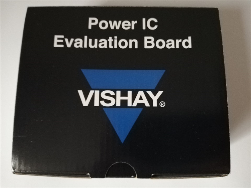
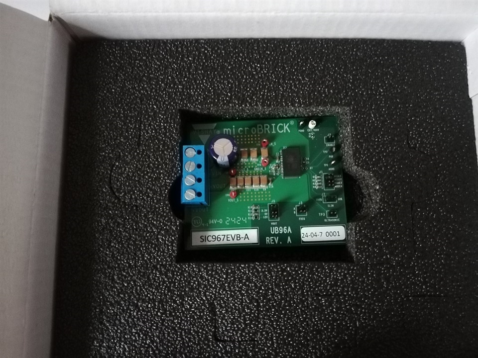
Evaluation kit has arrived (somewhat illegally by the way - it was released in error from customs office before clearance, so it is under some sort of correction procedure currently and it's legal status is unclear - thus unexpected delay in the roadtest) in an elegant cardboard box, filled in some sort of hard foam filling with a cut-out for the module.
| {gallery}Module unboxing |
|---|
|
The box |
|
Foam filling |
|
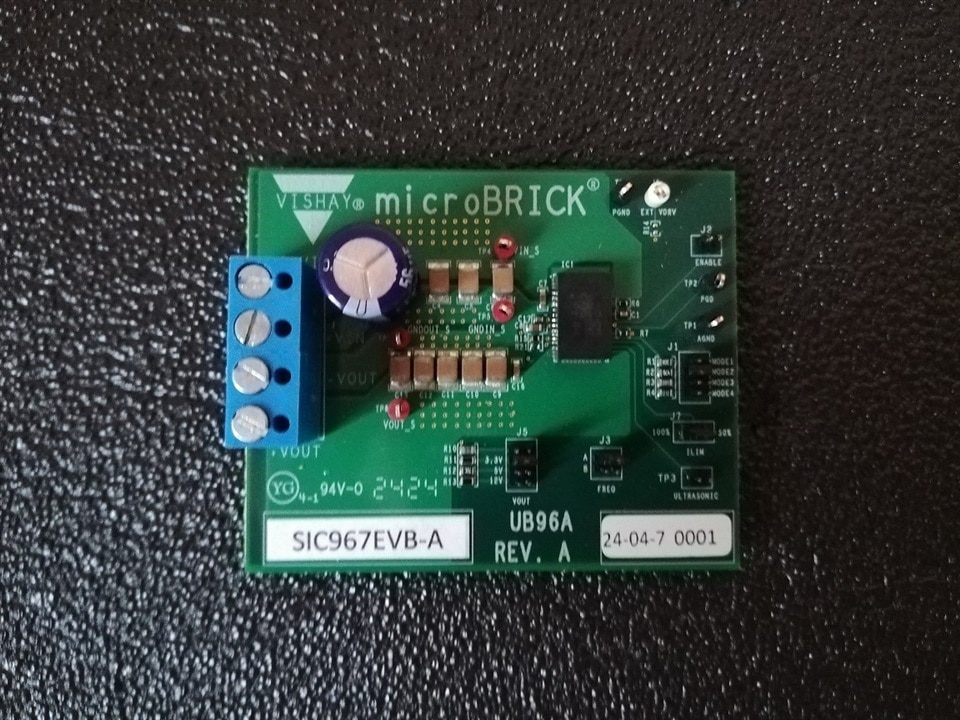
Top side view |
|
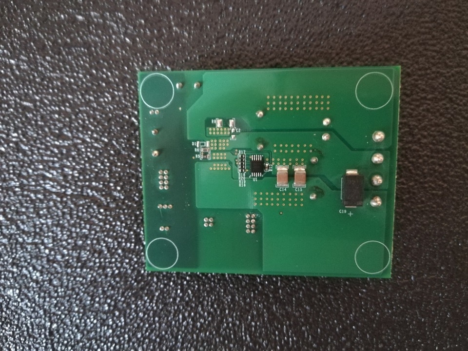
Bottom side view |
Input and output of the module is terminated using screwed terminals allowing for firm connector placement, which is an important feature, especially when high currents are expected. Evaluation board has several test points prepared and a configuration of converter parameters is possible using jumpers.
This fact leads us to the first observation - jumpers are of less common type, with 1.27" pitch and lower than expected endurance. On the photo below, result of this feature is documented - probably during the transport, PCB entered between layers of foam filling and one jumper slightly bent contacts it was placed over. So - some care should be exercised when operating jumpers.
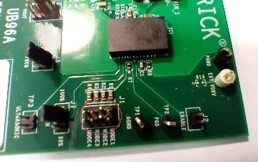
There are also no spare jumpers included (that is less important when standard jumpers are used, but not everyone has spare 1.27" jumpers available) and some configuration options (for example: 12 V output with 1 MHz clock) would need at least one additional jumper above the set included with the board.
One usually assumes that the schematics of the module corresponds to the module itself. Well - this case is somewhat different. First indication of that fact was Jan Cumps discovery that the module starts operating at the input voltage much lower than stated in the datasheet, which includes following statement:
Connect to a voltage source: 36 V to 50 V. This reference
board configures 32 V as the minimal value of input voltage
to enable the chip, and 27 V as the input voltage’s
under-voltage lockout (VIN UVLO) voltage.
And - to the surprise - module was enabled at the input voltage below 8 V.
After closer inspection the cause was identified as different than documented value of R5 resistor (10 kΩ instead of expected 2 kΩ), which led to lowering of enable voltage to about 7.5 V and undervoltage protection level to 6.4 V.
Then, additional differences were visually identified (side note - some components are installed with markings visible [and those are probably considered as of interest to the user and meant to be field replaceable if necessary] and others are placed with marked side down; only components with visible markings were checked).

Those differences (marked with red ovals on the schematics) are summarized below.
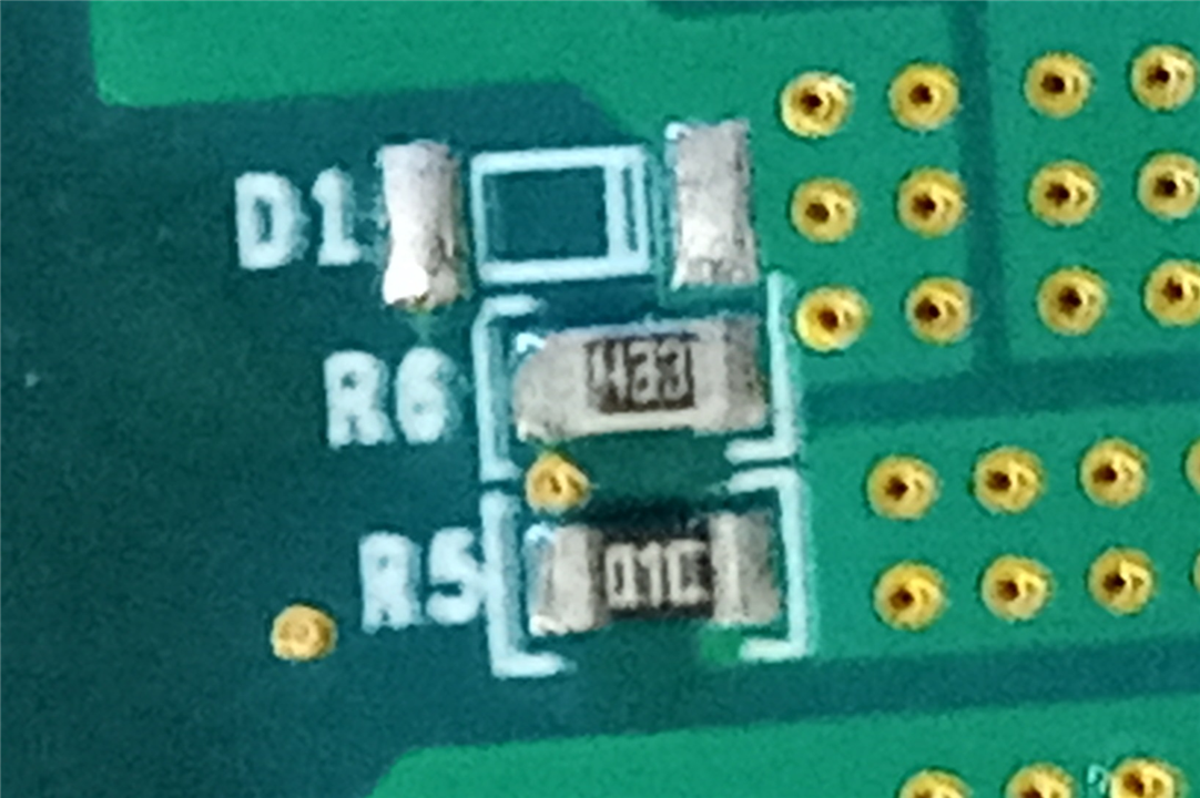
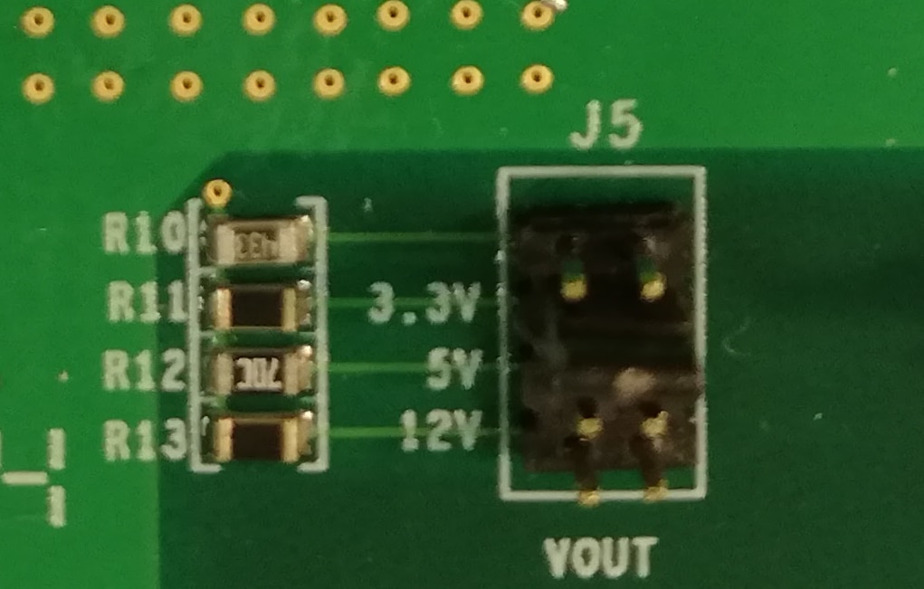
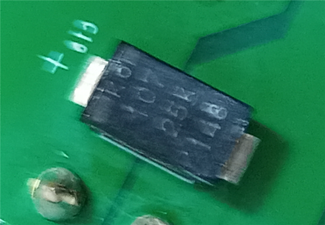
Three last changes are particularly interesting. Change of R5 and R10 resistors was probably caused by a desire to prevent user errors - as original board was supposed to be run from at least 32 V and there was option to select "unregulated" output voltage (J1 position 1-2, connected originally to a "not installed" voltage divider resistor R10), there was an easy way to destroy 25 V rated output capacitors.
After this change:
But the documentation should be updated to reflect those changes.
This discovery leads to another interesting topic: output voltage range. Datasheet of SIC967 states that "recommended output voltage" should be in 0.8 V - 15 V range. Evaluation board's datasheet - in turn - contains the following information:
Note
• The output capacitors are rated to 25 V. Should a higher output
voltage be required, the output capacitors should be changed to
ones with an appropriate higher voltage rating
There are two interesting facts in this note: the manufacturer expects the board to be user-modifiable and that the output voltage can be set to at least 25 V.
So - why is the recommended output voltage limited to the 15 V? Some answer can be found in microBUCK evaluation board's documentation, where bill of materials includes several positions describing main inductor (L1), with the values described as below:
Taking into consideration that microBRICKs have inductor built-in, some compromise is to be expected.
Then another question arises - what is value of built-in inductor? Datasheet is not providing that answer, in fact it contains some equations (probably ported as-is from microBUCK datasheet) that are using component values not provided by the documentation - like below equation for minimum value of output capacitor that is dependent on the (missing) inductor value
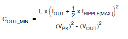
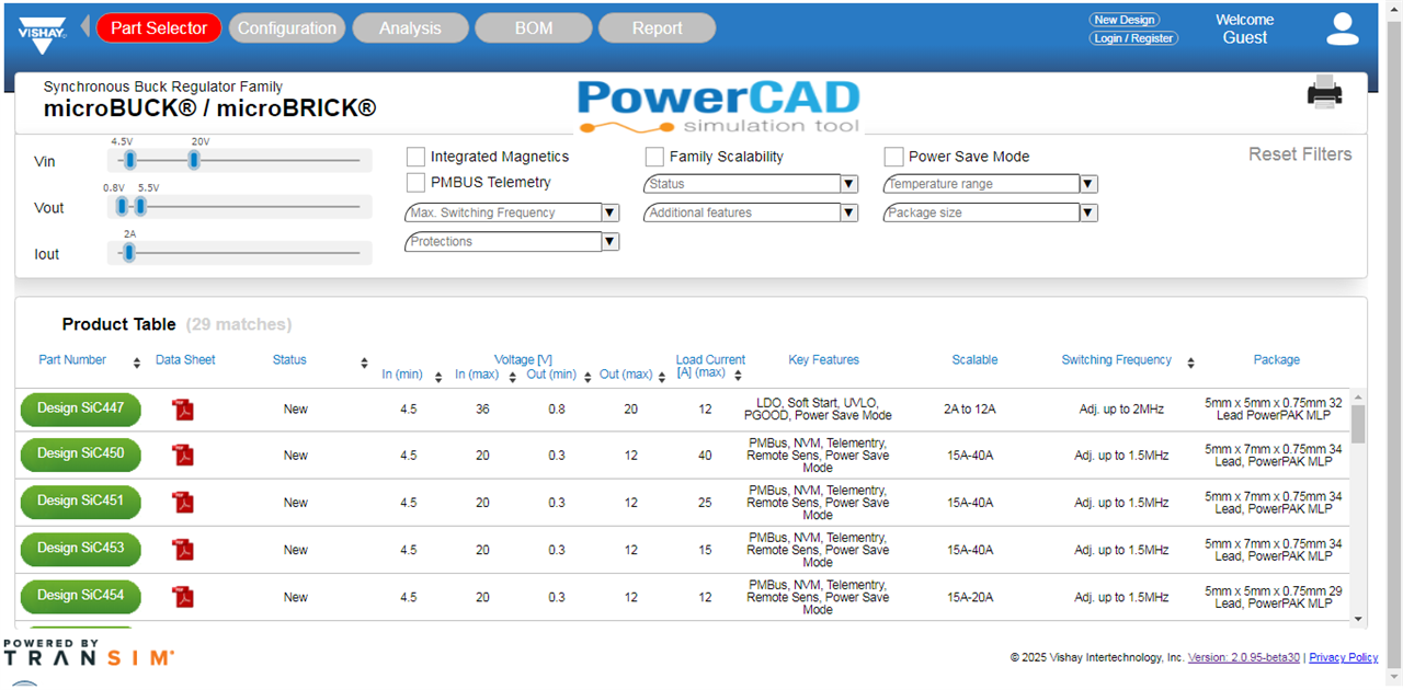
And here enters converter design software provided by the manufacturer. It is called PowerCAD and is advertised as more advanced than the competitor's oferring. Typical session (after accepting a legal disclaimer), starts with selecting a regulator from either microBUCK or microBRICK family. Regulator can be selected by the part number or using some selection criteria
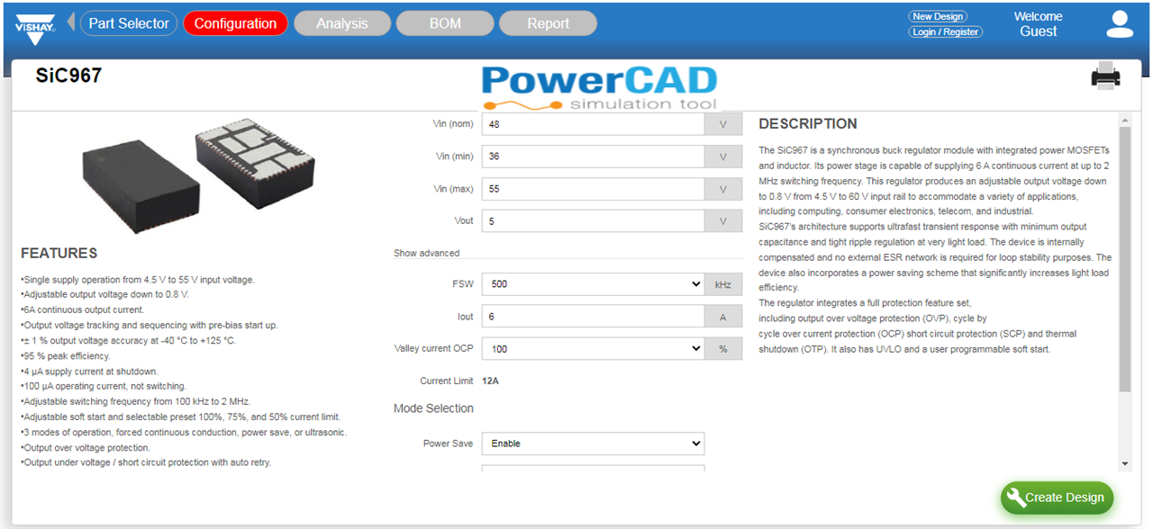
then, design parameters can be selected
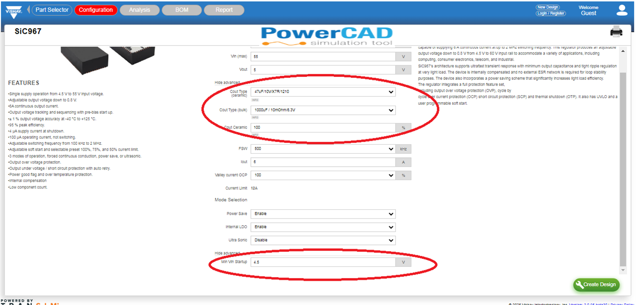
with some more advanced options (like startup voltage and output capacitor types and composition) hidden by default
For our microBRICK converter, switching frequency can be only selected from the predefined list of:
This is some limitation compared to microBUCK configuration, when operating frequency can be set "by hand" from the full range of values (like below)
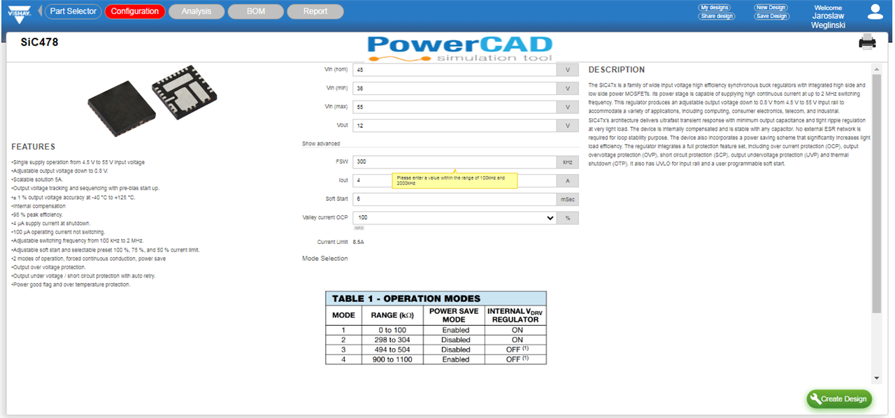
Given the fact that the evaluation board's predefined parameters are like below:

it seems we have limited cross-section between PowerCAD settings and the board configuration. Fortunately, operating frequency is output voltage dependent (using the equation below)
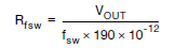
so, three positions of the frequency setting switch (J3) translate to much larger set of possible frequencies (especially given the fact that inclusion of R10 resistor gives us another predefined output voltage of 4.2 V).
Next step generates a schematics (like below)
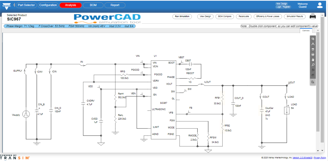
Additional options are available after creating an account - after that we can run simulations

and calculate expected efficiency, power losses and thermal characteristics (which is advertised as unique to this software)
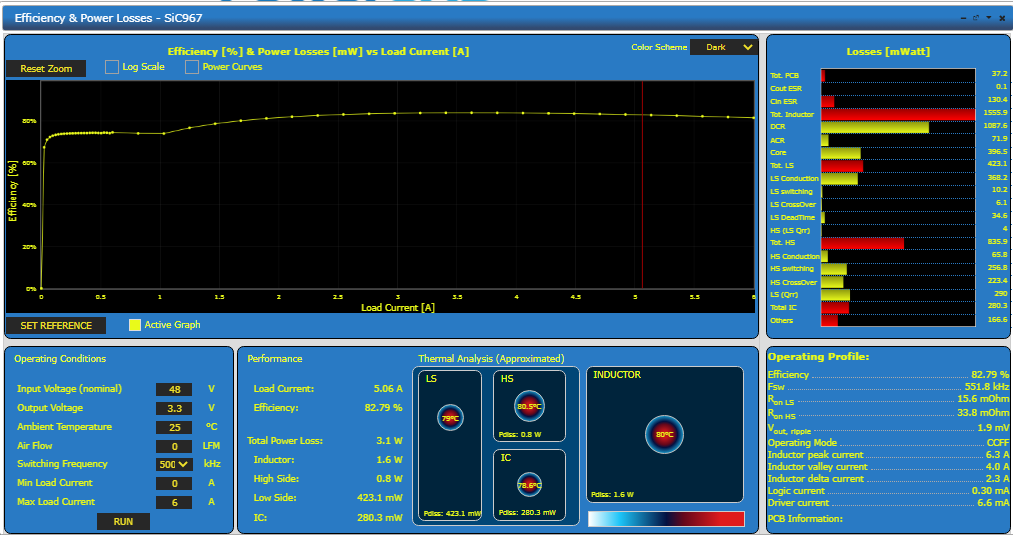
As we have mentioned earlier, simulation software seems to have limited parameter cross-section with the development board configuration options, so in the first step let's see what can be configured besides settings printed on the board (and in the datasheet).
First - we have another preset output voltage (thanks to including R10 resistor), which is giving us the choice of:
Second - as the operating frequency is output voltage dependent, three choices of J3 jumper translates to the following possible operating frequencies (values also present in PowerCAD are highlighted):
Next - to check calculation repeatability and calculate missing values from the datasheet, let's try to calculate inductor value. Using the equations from Analog Devices or Richtek documentation:


and simulation output (for various output voltages and operating frequencies), obtained from simulation stage of the PowerCAD (it is worth noting that not only signal values can be calculated, but also more advanced parameters like ripple current value)

gives very similar results of about 3 μH - with most distant calculations being for high frequency (12V/1Mhz and 5V/1MHz) or low output voltage (1V/300 kHz), which may hint at limited simulation accuracy at edge cases.
Another interesting observation is an output capacitor's value - most simulation results advise at least 10-20 22 μF ceramic capacitor set - which explains addition of 100 μF C19 on the development board:


The next planned test was an load change response, but the results are probably mostly influenced by the inductance of the load, not the converter behavior. Following plot shows a response to load change from 0 A to 3A and again to 0 A with the board configured for 3.3 V output and 400 kHz frequency.
High amplitude and high frequency ringing was observed (especially during load switch-off), but given it's frequency range (horizontal scale is 200 ns and vertical 2 V) it is most probably caused by the parasitic inductance of the 1 Ω load resistor (selected as metal film instead of wire-wound one to limit the influence of it's impedance but still not good enough it seems).

In my opinion this evaluation board is a low-cost (only slightly more expensive than the converter chip itself) evaluation tool that is greatly expanding the possibilities of testing the converter, beyond current design software capabilities and the available documentation. As a reference design it can be used to test configurations not possible to configure in the software provided.
On the other hand, design software (currently in beta - according to the version identifier displayed) and documentation could be expanded to:
and the board itself can be modified by using standard jumper size for better endurance.
Another observation is that the some advertised advantages of microBRICK regulator (mainly higher than microBUCK family attainable switching frequency) cannot be currently either simulated or easily set on the evaluation board.