RoadTest: Apply to Test the Arduino Nano R4!
Author: neerajrd82
Creation date:
Evaluation Type: Evaluation Boards
Did you receive all parts the manufacturer stated would be included in the package?: True
What other parts do you consider comparable to this product?: STM32F373CCT6,MK40DX256VLK10,ATSAM4LC8C,EFM32GG11B420F2048GL64
What were the biggest problems encountered?: Complete USB failure – Board not detected (no COM port), blocking normal development via Arduino IDE Ineffective standard recovery methods – Bootloader reset and typical Arduino fixes did not work Complex root cause – Clock misconfiguration impacting USB initialization required deep MCU-level analysis Limited low-level documentation – Insufficient clarity on register-level configuration and clock dependencies for debugging such failures Shift to hardware-level debugging – Required use of SWD + J-Link, full chip erase, and reflash to recover the system
Detailed Review:
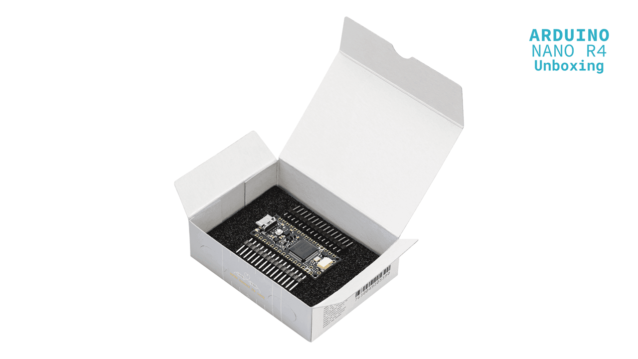
The Arduino Nano R4 was received in standard Arduino packaging with the board securely enclosed in an anti-static cover.
The inclusion of unsoldered headers allows flexibility depending on application (breadboard vs embedded use).
To prepare the board for testing, the supplied Berg strip headers were manually soldered.
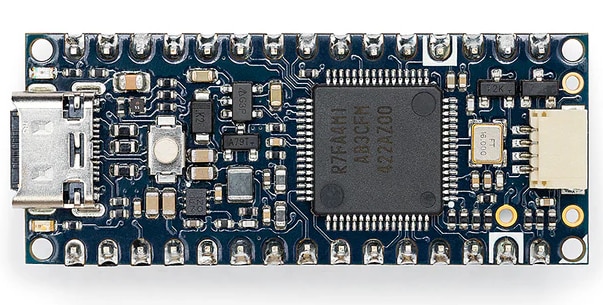
After soldering, the board was connected to the system using a USB Type-C cable.
At this stage, the board appeared non-functional and inaccessible
To investigate the issue, the following troubleshooting resource was referred:
Since USB depends on correct timing:
Any misconfiguration in system clock or startup code can completely disable USB communication.
Next, the official Arduino recovery guide was followed:
Result:
This prevented low-level recovery
The official guide assumes:
It does not fully address:
Based on experimentation, the failure was attributed to:
The Arduino Nano R4 behaves like a professional MCU platform, but without equivalent recovery infrastructure.
| Parameter | Observation |
|---|---|
| USB dependency | High |
| Recovery ease | Limited |
| Bare-metal tolerance | Sensitive |
| Debug accessibility | Restricted |
11. Switching over to SWD debug access to recover the target chip R7FA4M1AB3CFM mounted on Arduino Nano R4 board:
Now, i would like to refer to official schematics of Arduino Nano R4 given on this link:
https://docs.arduino.cc/resources/schematics/ABX00142-schematics.pdf
Here are 3 important observations about above picture are given below required for SWD bebug access:
1. MD pin of MCU given on JP1 connector pin no 13. -> This pin should be connected with SWCLK pin of debugger.
2. RESET pin of MCU given on JP2 connector pin no 3. -> This pin should be connected with RESET pin of debugger.
3. VUSB pin of MCU given on JP1 connector pin no 12 -> This pin should be given +5VDC from debugger USB power supply. 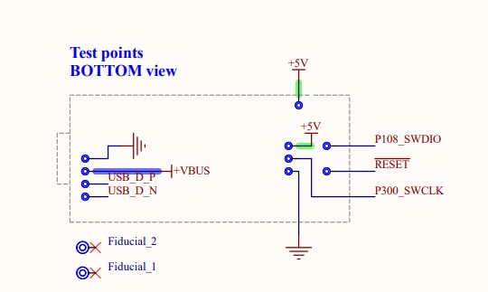
Here are some important observations about above picture are given below required for SWD bebug access:
1. P108_SWDIO & P300_SWCLK are required to connected with any compatible debugger -> Jlink / CMSIS-DAP / Renesas made Emulator
2. Very-very important point : P300_SWCLK & MD pin of MCU given on JP1 connector pin no 13 should be shorted with each other & connected to SWCLK line from debugger side.
Again by chance, i already possess this evaluation kit made by renesas: 
This board already have onboard Jlink OB lite debugger mounted on this kit. So, i decided to connect this debugger to Arduino Nano r4 while totally disconnecting on board target chip.
Now, referring to schematics of this kit which are found in ek-ra2l1-v1-designpackage.zip , these are important points everybody needs to consider for connections given below:
Please! download ek-ra2l1-v1-designpackage.zip from Renesas website.
Now, given below is important section of debugger to get connected with external target chip
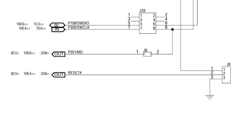
Important Note: all jumpers shown in this diagram needs to taken out totally, to cut off the onboard target chip for debugger connections.
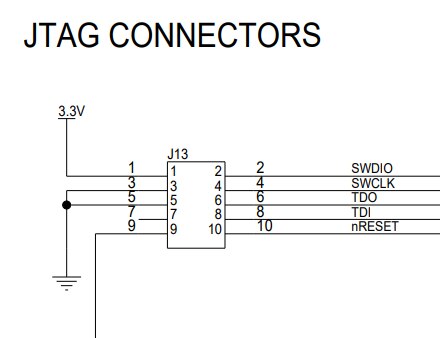
J13 connector shown above is not populated in actual kit, so all the connector pads are exposed which were directly soldered for debugger connection with Arduino Nano r4 board.

In above picture, 5V power supply can be easily seen which was connected with Arduino Nano R4 board to get power up using debugger USB power supply.
J-link Commander after getting correct connection from debugger will give below message corresponding to Arduino Nano R4 board:
Device "R7FA4M1AB" selected.
Connecting to target via SWD
InitTarget() start
Identifying target device...
SWD selected. Executing JTAG -> SWD switching sequence...
Initializing DAP...
DAP initialized successfully.
Low power mode detected. Waking device from low power mode.
InitTarget() end - Took 14.5ms
Found SW-DP with ID 0x5BA02477
DPIDR: 0x5BA02477
CoreSight SoC-400 or earlier
Scanning AP map to find all available APs
AP[2]: Stopped AP scan as end of AP map has been reached
AP[0]: AHB-AP (IDR: 0x24770011, ADDR: 0x00000000)
AP[1]: APB-AP (IDR: 0x44770002, ADDR: 0x01000000)
Iterating through AP map to find AHB-AP to use
AP[0]: Core found
AP[0]: AHB-AP ROM base: 0xE00FF000
CPUID register: 0x410FC241. Implementer code: 0x41 (ARM)
Found Cortex-M4 r0p1, Little endian.
FPUnit: 6 code (BP) slots and 2 literal slots
CoreSight components:
ROMTbl[0] @ E00FF000
[0][0]: E000E000 CID B105E00D PID 000BB00C SCS-M7
[0][1]: E0001000 CID B105E00D PID 003BB002 DWT
[0][2]: E0002000 CID B105E00D PID 002BB003 FPB
[0][3]: E0000000 CID B105E00D PID 003BB001 ITM
[0][4]: E0040000 CID B105900D PID 000BB9A1 TPIU
[0][5]: E0041000 CID B105900D PID 000BB925 ETM
[0][6]: E0042000 CID B105900D PID 002BB908 CSTF
[0][7]: E0043000 CID B105900D PID 001BB961 TMC
[0][8]: E0044000 CID B105F00D PID 001BB101 TSG
Memory zones:
Zone: "Default" Description: Default access mode
Cortex-M4 identified.
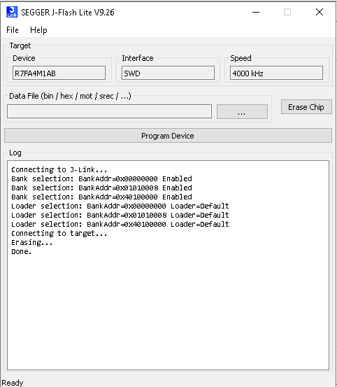
So, SEGGER J-FLASH LITE was able to program Arduino Nano r4 board successfully, below picture demonstrates that:

So, SEGGER J-FLASH LITE was able to erase Arduino Nano r4 board successfully, below picture demonstrates that:
I m showing the picture of actual physical connections with debugger & Arduino Nano R4 board given below:
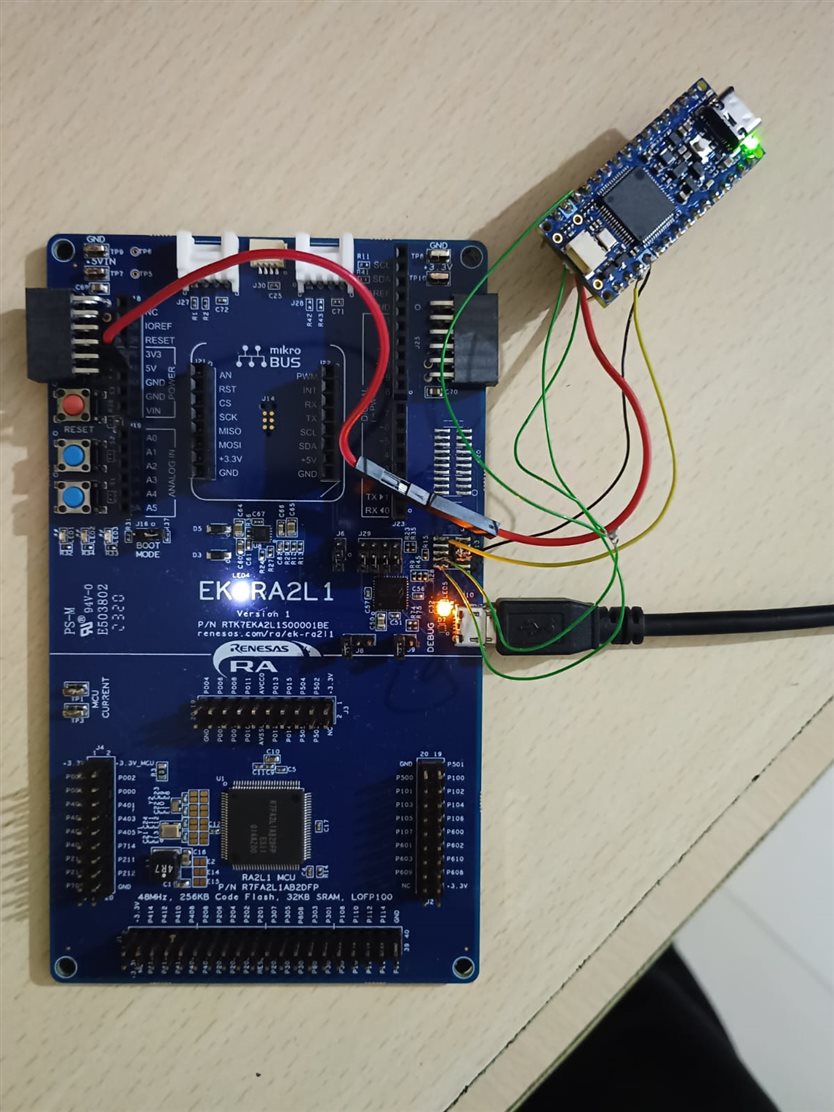
Important observation noted: I was able to recover original preloaded program which was actually loaded in Arduino Nano R4 at time of arrival using jlink debugger.
12. Switching over the development of target chip R7FA4M1AB3CFM mounted on Arduino Nano R4 board from Arduino IDE into Keil MDK ARM :
Here you have to use Renesas smart configurator with Output configured for Keil MDK ARM.
Select the clock settings given below in Renesas smart configurator in given screenshot:
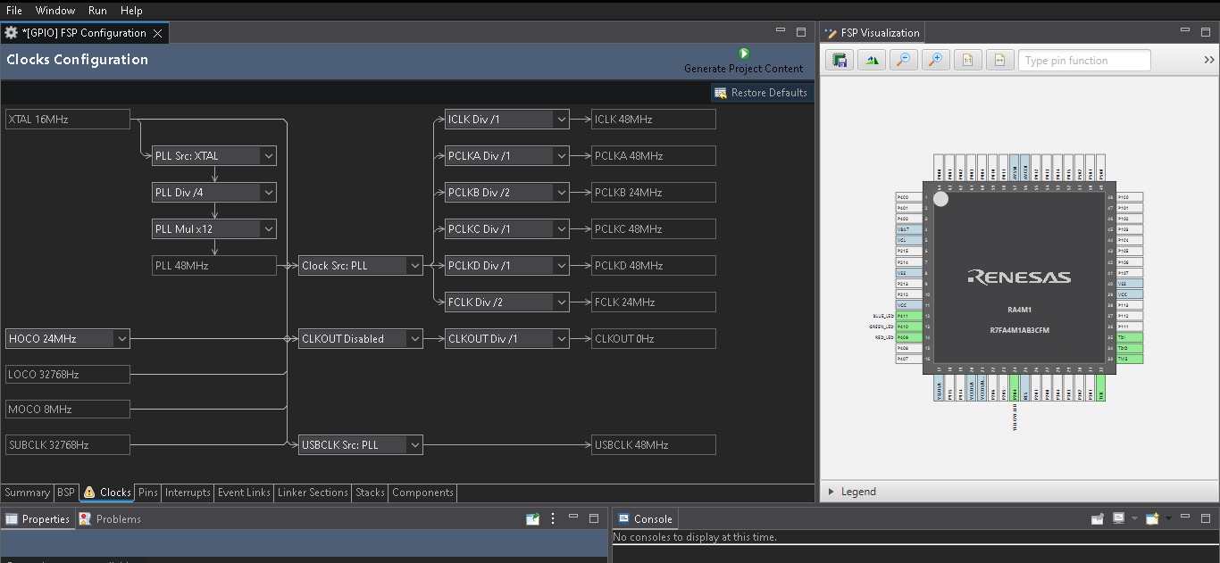
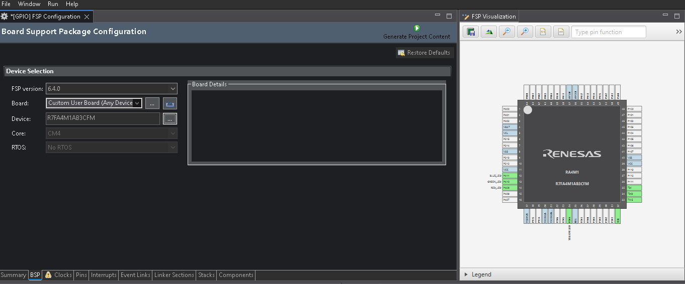
Select Board : Custom User board (Any Device) as shown in screenshot given below:
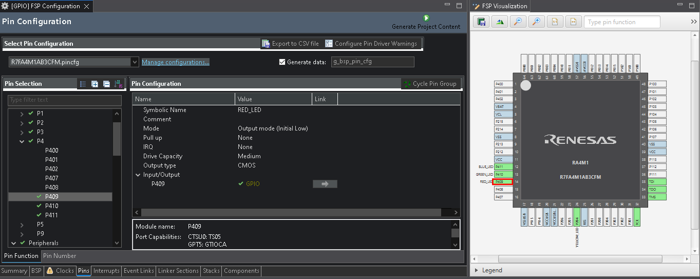
Pin function select is shown in given screenshot :
BSP options are shown in below screenshot: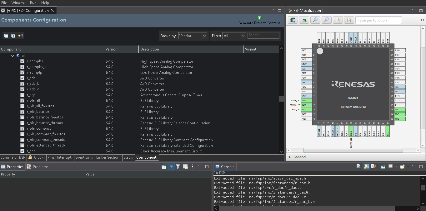
In bsp options, just select bare metal & No RTOS to include. Also select "Generate Project option" option to generate Blinky program in this configurator as shown below: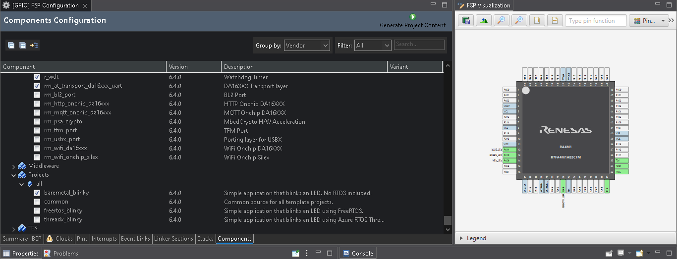
Below given picture demonstrates the output given by Renesas smart configurator for Keil MDK ARM:
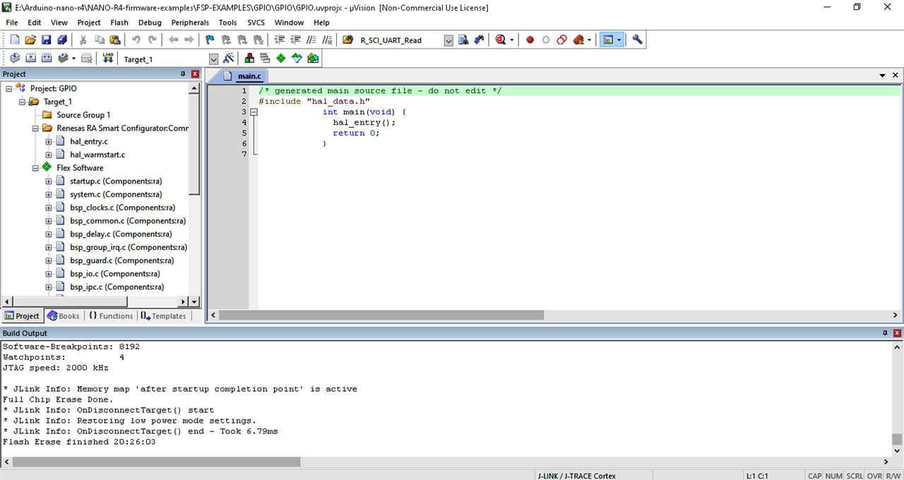
To run this program correctly, Please! do the following steps:
Search & comment this line given below:
FSP_HARDWARE_REGISTER_WAIT(R_RTC->RCR2_b.RESET, 0); -> This line is found in bsp_clocks.c
Important observation: Debugger gets stuck on above line.
Update on 31/03/2026:
Keil screenshot on C/C++ tab: 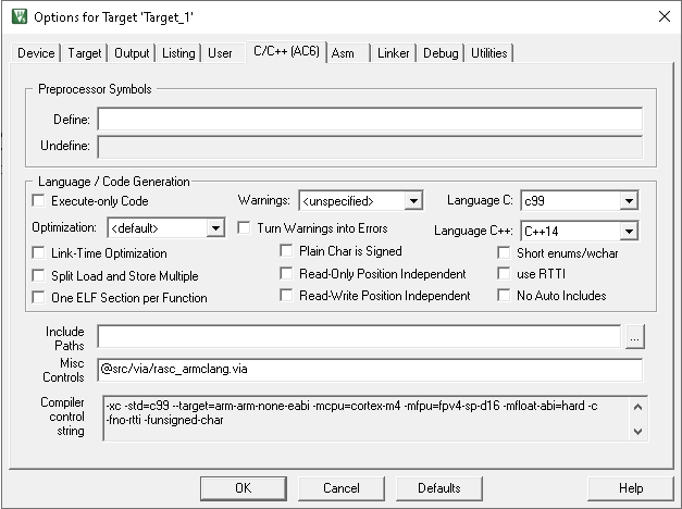
Keil screenshot on Asm tab: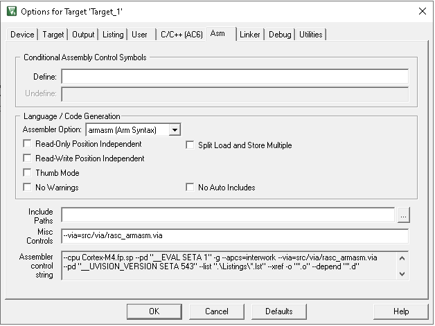
Keil screenshot on Linker tab:
Configure the below settings in Flash download of keil as shown screenshot given below: 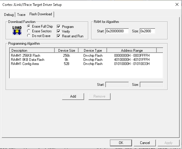
Apply the above settings, then follow the below given steps:
Generate the hex file.
Completely erase the chip.
Then program the chip using download button in keil.
Expected result: You should be able to RGB LED as single white LED glowing brightly but without blinking.
Now, after resolving settings issues, renesas flash programmer is also working, screenshots are given below:

Programming messages by Renesas Flash Programmer are given below:
Loading File (E:\Arduino-nano-r4\led.hex) CRC-32=8D56F9F1
Target device : RA
Connecting the tool
J-Link Firmware: J-Link OB-S124 compiled Dec 10 2025 15:52:46
Tool : J-Link (SEGGER J-Link-OB-S124), Interface : SWD
Connecting to the target device
Connecting to the target device
Communication speed : 6.0 MHz
Signature:
Device: RA
Device Code: 00160447
Erasing the selected blocks
[Code Flash 1] 0x00000000 - 0x0003FFFF size : 256 K
[Data Flash 1] 0x40100000 - 0x40101FFF size : 8 K
Erasing the selected blocks
[Code Flash 1] 0x00000000 - 0x0003FFFF size : 256 K
[Data Flash 1] 0x40100000 - 0x40101FFF size : 8 K
Writing data to the target device
[Code Flash 1] 0x00000000 - 0x0003FFFF size : 256 K
[Data Flash 1] 0x40100000 - 0x40101FFF size : 8 K
[Config Area 1] 0x01010008 - 0x01010033 size : 44
Verifying data
[Code Flash 1] 0x00000000 - 0x0003FFFF size : 256 K
[Data Flash 1] 0x40100000 - 0x40101FFF size : 8 K
[Config Area 1] 0x01010008 - 0x01010033 size : 44
Setting the target device
Disconnecting the tool
Operation completed.
Important observation: This tool should be used to production programming rather than for development.
13. Build the whole project in keil bypassing Renesas smart configurator
If you do not want to use code generated by Renesas smart configurator -> then it is still long learning curve, but some how i managed to reduce the number of files to taken from smart configurator & managed to write in register direct format. Also i have followed the steps given just above this section.
End result of above exercise is shown below screenshot: 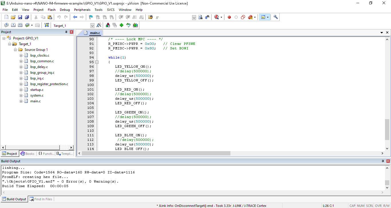
Of course, result was fabulous: I was able to blink RGB LED & AMBER LED independently bypassing the HAL library as mandated by Renesas.
Final Verdict:
When the Arduino Nano R4 loses USB functionality due to low-level firmware issues, recovery becomes complex and not be achievable using standard Arduino tools alone.
It requires the assistance of JLINK/ CMSIS DAP / Renesas EMULATOR to recover from all types of firmware issues.
Also this board requires the erase of whole chip to prevent the hang-up.
The Arduino Nano R4 delivers powerful Renesas-based performance, but its recovery mechanisms need significant improvement to support advanced embedded development workflows.
Renesas flash programmer is not reliable at all, it does not connect with Jlink reliably to sense the chip.
There is steep learning curve for bare metal development on register direct access bypassing HAL layer by Renesas.
Renesas needs to improve on all these parameters.
MY SINCERE THANKS FOR ELEMENT 14 Community to give me to chance to test the arduino nano R4 board.


