element14 Community
element14 Community
    Register Log In
  • Site
  • Search
  • Log In Register
  • Community Hub
    Community Hub
    • What's New on element14
    • Feedback and Support
    • Benefits of Membership
    • Personal Blogs
    • Members Area
    • Achievement Levels
  • Learn
    Learn
    • Ask an Expert
    • eBooks
    • element14 presents
    • Learning Center
    • Tech Spotlight
    • STEM Academy
    • Webinars, Training and Events
    • Learning Groups
  • Technologies
    Technologies
    • 3D Printing
    • FPGA
    • Industrial Automation
    • Internet of Things
    • Power & Energy
    • Sensors
    • Technology Groups
  • Challenges & Projects
    Challenges & Projects
    • Design Challenges
    • element14 presents Projects
    • Project14
    • Arduino Projects
    • Raspberry Pi Projects
    • Project Groups
  • Products
    Products
    • Arduino
    • Avnet & Tria Boards Community
    • Dev Tools
    • Manufacturers
    • Multicomp Pro
    • Product Groups
    • Raspberry Pi
    • RoadTests & Reviews
  • About Us
    About the element14 Community
  • Store
    Store
    • Visit Your Store
    • Choose another store...
      • Europe
      •  Austria (German)
      •  Belgium (Dutch, French)
      •  Bulgaria (Bulgarian)
      •  Czech Republic (Czech)
      •  Denmark (Danish)
      •  Estonia (Estonian)
      •  Finland (Finnish)
      •  France (French)
      •  Germany (German)
      •  Hungary (Hungarian)
      •  Ireland
      •  Israel
      •  Italy (Italian)
      •  Latvia (Latvian)
      •  
      •  Lithuania (Lithuanian)
      •  Netherlands (Dutch)
      •  Norway (Norwegian)
      •  Poland (Polish)
      •  Portugal (Portuguese)
      •  Romania (Romanian)
      •  Russia (Russian)
      •  Slovakia (Slovak)
      •  Slovenia (Slovenian)
      •  Spain (Spanish)
      •  Sweden (Swedish)
      •  Switzerland(German, French)
      •  Turkey (Turkish)
      •  United Kingdom
      • Asia Pacific
      •  Australia
      •  China
      •  Hong Kong
      •  India
      •  Japan
      •  Korea (Korean)
      •  Malaysia
      •  New Zealand
      •  Philippines
      •  Singapore
      •  Taiwan
      •  Thailand (Thai)
      •  Vietnam
      • Americas
      •  Brazil (Portuguese)
      •  Canada
      •  Mexico (Spanish)
      •  United States
      Can't find the country/region you're looking for? Visit our export site or find a local distributor.
  • Translate
  • Profile
  • Settings
Open Source Hardware
  • Technologies
  • More
Open Source Hardware
Forum Archaeology Resistivity Meter
  • Blog
  • Forum
  • Documents
  • Events
  • Polls
  • Members
  • Mentions
  • Sub-Groups
  • Tags
  • More
  • Cancel
  • New
Join Open Source Hardware to participate - click to join for free!
Actions
  • Share
  • More
  • Cancel
Forum Thread Details
  • Replies 332 replies
  • Subscribers 332 subscribers
  • Views 55119 views
  • Users 0 members are here
  • armp
  • archaeology resistivity meter
Related

Archaeology Resistivity Meter

kltm
kltm over 6 years ago

Hi I'm looking for ideas on an update to a resistivity meter for archaeology. The only published designs for diy were in 2 magazines. One was published in 1997 and the other in 2003. I have copies of both articles available. The reason behind this is the current high cost of available equipment, usually well beyond the reach of most archaeological groups. I've attached a basic block diagram. In the first magazine article the meter is very basic. It relied on the operators to write down the reading given as the survey was taken. Given that a normal survey grid is 20m x 20m and 1 reading is taken on every sq mtr there would be 400 readings to write down and then input into a program used to interpret the results. The later article is really an update to the first where a PIC has been added to record the readings. This again is prone to error, because eadings are taken manually by pressing a button.

I'm sure given the advances in electronics there must be better ways. 


image

  • Sign in to reply
  • Cancel

Top Replies

  • kltm
    kltm over 6 years ago in reply to michaelkellett +8
    Hi Michael This all sounds very interesting and encouraging. I see you have found the original article, the update is also on slideshare somewhere. I haven’t really thought much about cost, but as you…
  • michaelkellett
    michaelkellett over 6 years ago in reply to shabaz +7
    I can't live with that - I have to have symmetry The problem is that the Howland current pump doesn't constrain the voltage on the load at all when perfectly balanced - and my LTSpice model is unrealistically…
  • michaelkellett
    michaelkellett over 6 years ago in reply to michaelkellett +7
    AS promised - now for the phase sensitive detector. I couldn't easily model this in LTSpice, which is no great surprise because it needs multiplication and square roots. I used Simulink in MATLAB - which…
  • kltm
    kltm over 6 years ago in reply to michaelkellett

    Hi Michael

    I agree with your points entirely, I also agree that we need to get to a working prototype as quickly as possible, I'm sure this will prove the theory.

    Ken

    • Cancel
    • Vote Up +3 Vote Down
    • Sign in to reply
    • Cancel
  • davemartin
    davemartin over 6 years ago in reply to michaelkellett

    Thanks Michael,


    I have heard of V=IR before, the problem is that it is not a simple resistor. At 50m between P1C1 and P2C2, the 'device' under test is approximately thirty thousand cubic metres of potentially-soggy interference-laden non-homogeneous earth; and if you go out to 100m as Ken mentioned he could with his commercial rig, its over a quarter of million cubic metres of earth in the circuit.


    I'm sorry if I'm not being clear, if I may, I'll try and explain the sequence differently.


    Phase 1: leading edge of square wave, try to apply, say, 10mA.

    Constant current source will apply as much voltage as it is able/allowed to.

    It can take maybe 2mS or more to get the injection stable(*1). There is no point in trying to measure until the injection is stable.(*2)


    Phase 2:

    Injection is stable, starting measuring P1P2, repeat as many times and as fast as possible until end of pulse. Apply filtering to try and get best reading.


    Phase 3:

    Reverse polarity.


    Repeat above until get consistent filtered voltage and hence res, or until some form of timeout. Typically may sample for 20-50 full cycles.


    *1) 2mS is a reasonable time for injection to stabilise, and usually works fine with 137Hz reversal, but in some conditions the 3.75mS pulse can expire before injection stabilises, which is why some modern commercial kit offers option to reduce reversal rate down as low as 17.5Hz

    *2) I appreciate you could use processor ADC as, I think both you and Shabaz mentioned, to monitor this by looking for output voltage is stable and not maxed-out, and that might be sufficient indication for square-wave, but still believe that proper digitised value of the instantaneous current actually being injected will be necessary to explore non-square-wave excitation.


    Dave

    • Cancel
    • Vote Up +1 Vote Down
    • Sign in to reply
    • Cancel
  • michaelkellett
    michaelkellett over 6 years ago in reply to kltm

    OK - great - I've made some progress on designing the input circuits and I might be able to post something by the weekend.

    Unfortunately for this project, real work has picked up somewhat recently (although it's a welcome thing for me of course) so I have

    less time free than I had.


    I'm happy to take the electronic design as far as laying out a pcb and even building one or two but it would be nice to have a

    volunteer or two to do software !


    For now I'll post schematics as .pdf in this group - I can set up a Github repo if you would like (although I'm no expert in Git -so very

    happy for some one else to do it if they can.)


    MK

    • Cancel
    • Vote Up +2 Vote Down
    • Sign in to reply
    • Cancel
  • shabaz
    shabaz over 6 years ago in reply to michaelkellett

    Hi Michael,


    Better to be busy than not! : ) I've been a little tied up too, but will download the development environment and start getting used to the support libraries (not used ST's dev environment but am sure I can get up-to-speed quickly).. I'll be able to write code and test it on an off-the-shelf ST dev board, and then can try to bring up a board from a PCB as the hardware is developed.

    I'll order a dev-board just as soon as I can find the processor number.. I think you typed it but it's buried in the hundred comments : )


    EDIT: I think it is STM32L4R5VGT6 from a sketch, and the suitable board is NUCLEO-L4R5ZI (just a higher pin-count chip with I/O that can be ignored, and more RAM).

    If that's correct, I'll go ahead and get that ordered.

    Also, incidentally if it is that device, then Mbed OS is supported too : ) (Mbed doesn't support all processors, only very specific ones). I'm very familiar with that, and could speed up development a lot. (Mbed has an RTOS (RTX), huge suite of library functions, and a development environment famous for being online, but is downloadable - it uses GCC and Python scripts. But happy to use ST environment too. I could try both initially, until there's some skeleton code.

    • Cancel
    • Vote Up +1 Vote Down
    • Sign in to reply
    • Cancel
  • michaelkellett
    michaelkellett over 6 years ago in reply to shabaz

    I was hoping you might image


    I'll look at the implications of using the exact same processor as the Nucleo board - it's one less thing to worry about if the code just drops in.


    I have to say that my experience with RTOS and library code on these processors is very negative, but I've not used Mbed so that might be better.


    My usual route is Keil tools (not an option here because much too expensive) and my own register access level code for almost everything else.


    I'm interested in ST's development environment which I believe is truly open source.


    MK

    • Cancel
    • Vote Up +1 Vote Down
    • Sign in to reply
    • Cancel
  • kltm
    kltm over 6 years ago

    Hi I will take a look at setting up a github repository. Never done it before, but hopefully there will be some internet guidance. It’s a shame we can’t just have an element14 group, but that seems impossible. I think, other than that, the consensus was that we stay on element14, at least for the time being.

    Ken

    • Cancel
    • Vote Up +1 Vote Down
    • Sign in to reply
    • Cancel
  • michaelkellett
    michaelkellett over 6 years ago in reply to shabaz

    I've had a quick look at the Nucleo boards - there are two - one for the standard processor and one for the P version.

    Farnell have no stock of P type processors so I'm going for the standard version.

    (The P types can use an external SMPS to drive the core - I'll try to design our board to use either but I don't expect to

    use the external SMPS - it offers no advantages in this application.)

    I've ordered a Nucleo (Farnell 2845537)


    The Nucleo processor has 144 pins and 2M of flash. (The extra pins won't hurt and may help so I'll design the board for the same chip.)


    MK

    • Cancel
    • Vote Up 0 Vote Down
    • Sign in to reply
    • Cancel
  • Jan Cumps
    Jan Cumps over 6 years ago in reply to shabaz

    shabaz  wrote:


    ...


    ...I think it is STM32L4R5VGT6 from a sketch, and the suitable board is NUCLEO-L4R5ZI (just a higher pin-count chip with I/O that can be ignored, and more RAM).

    If that's correct, I'll go ahead and get that ordered.

    Also, incidentally if it is that device, then Mbed OS is supported too : ) (Mbed doesn't support all processors, only very specific ones). I'm very familiar with that, and could speed up development a lot. (Mbed has an RTOS (RTX), huge suite of library functions, and a development environment famous for being online, but is downloadable - it uses GCC and Python scripts. But happy to use ST environment too. I could try both initially, until there's some skeleton code.

    It's that device Farnell 2845537.Farnell 2845537.

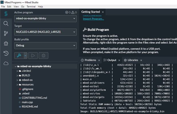
    I don't have one, but checked, and the off-line MBED studio supports it with MBED OS 6.

    image

    Also supported by CubeIDE so all options are open.

    • Cancel
    • Vote Up +2 Vote Down
    • Sign in to reply
    • Cancel
  • shabaz
    shabaz over 6 years ago in reply to michaelkellett

    Hi Michael,


    Great, I'll get that board ordered too.

    I've installed the ST dev environment to get some familiarity, and will try to sketch about how things could function in the software in the next couple of days.

    I'm thinking when it comes to the code, to write the first bits for both the ST environment and mbed environments, so that we have some options initially, and eventually just sticking with one stream as I get up-to-speed adding more and more code features (i.e. likely ST since you're familiar with it too).

    • Cancel
    • Vote Up +2 Vote Down
    • Sign in to reply
    • Cancel
  • michaelkellett
    michaelkellett over 6 years ago in reply to shabaz

    I'm not very familiar with the ST compiler tools - only the libraries. So I'm perfectly willing to be converted to mBed for this project.

    I'd be very interested to hear about your comparison of the tools.


    MK

    • Cancel
    • Vote Up +2 Vote Down
    • Sign in to reply
    • Cancel
<>
element14 Community

element14 is the first online community specifically for engineers. Connect with your peers and get expert answers to your questions.

  • Members
  • Learn
  • Technologies
  • Challenges & Projects
  • Products
  • Store
  • About Us
  • Feedback & Support
  • FAQs
  • Terms of Use
  • Privacy Policy
  • Legal and Copyright Notices
  • Sitemap
  • Cookies

An Avnet Company © 2026 Premier Farnell Limited. All Rights Reserved.

Premier Farnell Ltd, registered in England and Wales (no 00876412), registered office: Farnell House, Forge Lane, Leeds LS12 2NE.

Follow element14

  • X
  • Facebook
  • linkedin
  • YouTube