element14 Community
element14 Community
    Register Log In
  • Site
  • Search
  • Log In Register
  • Community Hub
    Community Hub
    • What's New on element14
    • Feedback and Support
    • Benefits of Membership
    • Personal Blogs
    • Members Area
    • Achievement Levels
  • Learn
    Learn
    • Ask an Expert
    • eBooks
    • element14 presents
    • Learning Center
    • Tech Spotlight
    • STEM Academy
    • Webinars, Training and Events
    • Learning Groups
  • Technologies
    Technologies
    • 3D Printing
    • FPGA
    • Industrial Automation
    • Internet of Things
    • Power & Energy
    • Sensors
    • Technology Groups
  • Challenges & Projects
    Challenges & Projects
    • Design Challenges
    • element14 presents Projects
    • Project14
    • Arduino Projects
    • Raspberry Pi Projects
    • Project Groups
  • Products
    Products
    • Arduino
    • Avnet & Tria Boards Community
    • Dev Tools
    • Manufacturers
    • Multicomp Pro
    • Product Groups
    • Raspberry Pi
    • RoadTests & Reviews
  • About Us
  • Store
    Store
    • Visit Your Store
    • Choose another store...
      • Europe
      •  Austria (German)
      •  Belgium (Dutch, French)
      •  Bulgaria (Bulgarian)
      •  Czech Republic (Czech)
      •  Denmark (Danish)
      •  Estonia (Estonian)
      •  Finland (Finnish)
      •  France (French)
      •  Germany (German)
      •  Hungary (Hungarian)
      •  Ireland
      •  Israel
      •  Italy (Italian)
      •  Latvia (Latvian)
      •  
      •  Lithuania (Lithuanian)
      •  Netherlands (Dutch)
      •  Norway (Norwegian)
      •  Poland (Polish)
      •  Portugal (Portuguese)
      •  Romania (Romanian)
      •  Russia (Russian)
      •  Slovakia (Slovak)
      •  Slovenia (Slovenian)
      •  Spain (Spanish)
      •  Sweden (Swedish)
      •  Switzerland(German, French)
      •  Turkey (Turkish)
      •  United Kingdom
      • Asia Pacific
      •  Australia
      •  China
      •  Hong Kong
      •  India
      •  Korea (Korean)
      •  Malaysia
      •  New Zealand
      •  Philippines
      •  Singapore
      •  Taiwan
      •  Thailand (Thai)
      • Americas
      •  Brazil (Portuguese)
      •  Canada
      •  Mexico (Spanish)
      •  United States
      Can't find the country/region you're looking for? Visit our export site or find a local distributor.
  • Translate
  • Profile
  • Settings
Open Source Hardware
  • Technologies
  • More
Open Source Hardware
Forum Archaeology Resistivity Meter
  • Blog
  • Forum
  • Documents
  • Events
  • Polls
  • Members
  • Mentions
  • Sub-Groups
  • Tags
  • More
  • Cancel
  • New
Join Open Source Hardware to participate - click to join for free!
Actions
  • Share
  • More
  • Cancel
Forum Thread Details
  • Replies 332 replies
  • Subscribers 321 subscribers
  • Views 44463 views
  • Users 0 members are here
  • armp
  • archaeology resistivity meter
Related

Archaeology Resistivity Meter

kltm
kltm over 5 years ago

Hi I'm looking for ideas on an update to a resistivity meter for archaeology. The only published designs for diy were in 2 magazines. One was published in 1997 and the other in 2003. I have copies of both articles available. The reason behind this is the current high cost of available equipment, usually well beyond the reach of most archaeological groups. I've attached a basic block diagram. In the first magazine article the meter is very basic. It relied on the operators to write down the reading given as the survey was taken. Given that a normal survey grid is 20m x 20m and 1 reading is taken on every sq mtr there would be 400 readings to write down and then input into a program used to interpret the results. The later article is really an update to the first where a PIC has been added to record the readings. This again is prone to error, because eadings are taken manually by pressing a button.

I'm sure given the advances in electronics there must be better ways. 


image

  • Sign in to reply
  • Cancel

Top Replies

  • kltm
    kltm over 5 years ago in reply to michaelkellett +8
    Hi Michael This all sounds very interesting and encouraging. I see you have found the original article, the update is also on slideshare somewhere. I haven’t really thought much about cost, but as you…
  • michaelkellett
    michaelkellett over 5 years ago in reply to shabaz +7
    I can't live with that - I have to have symmetry The problem is that the Howland current pump doesn't constrain the voltage on the load at all when perfectly balanced - and my LTSpice model is unrealistically…
  • michaelkellett
    michaelkellett over 5 years ago in reply to michaelkellett +7
    AS promised - now for the phase sensitive detector. I couldn't easily model this in LTSpice, which is no great surprise because it needs multiplication and square roots. I used Simulink in MATLAB - which…
  • fmilburn
    fmilburn over 5 years ago in reply to genebren

    When I was a boy there was a shell midden behind our house on the edge of town that was excavated and the local kids were allowed to participate.  I remember the squares that were laid out, the trowels, and using a rule to measure depth.  There weren't any grand discoveries but it was great fun.  That was many years ago.  The area is now filled in and there houses on top of what used to be a shallow horseshoe lake and woods.

    • Cancel
    • Vote Up +5 Vote Down
    • Sign in to reply
    • Cancel
  • michaelkellett
    michaelkellett over 5 years ago in reply to shabaz

    TI do a nice DAC available in 16 or 12 bit versions fro £4.61 or £2.03 (DAC80501 or DAC60501).

    SPI in and voltage out. It has a built in voltage reference which we can use for everything else as well.


    So we need to connect the DAC to the FPGA in the block diagram rather than to the micro.


    MK

    • Cancel
    • Vote Up +4 Vote Down
    • Sign in to reply
    • Cancel
  • phoenixcomm
    phoenixcomm over 5 years ago in reply to michaelkellett

    michaelkellett

    image

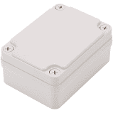
    Most Likely two boxes one the PI & HDA, Power, etc. The second box on the hand bar would have your keyboard, LED display, and most likely some switches to control the probes.  Personally I would interconnect the two boxes via the CAN bus. Waterproof boxes are easy to find they are all gasketed and made from abs. You can also pick up a Pelican case as well. make sure that you waterproof cables, and connectors. To power the 'thing '  you could b powered from a motorbike or small car battery.

    • Cancel
    • Vote Up +2 Vote Down
    • Sign in to reply
    • Cancel
  • shabaz
    shabaz over 5 years ago in reply to shabaz

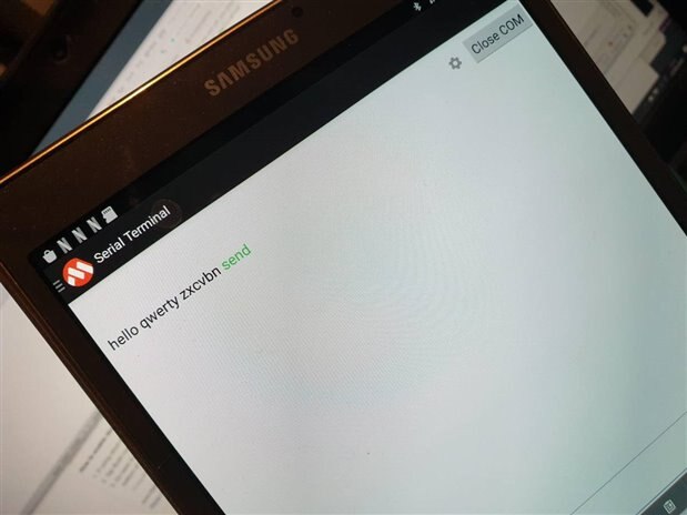
    115200 baud confirmed functioning.

    So, one day the snuffler software can be replaced (or at least partially) with Android code if desired. Or could be used to e-mail or upload the data in real-time so someone can remotely check it while the survey is still being performed.

    The test setup was as shown here:

    image


    image

    • Cancel
    • Vote Up +6 Vote Down
    • Sign in to reply
    • Cancel
  • paul_d_arch
    paul_d_arch over 5 years ago in reply to shabaz

    Hi Guys,


    I've been reading your plans on Element14 for an Archaeology Resistivity Meter after seeing it on Facebook.


    Its very exciting. Have you considered using a Raspberry Pi unit? I don't know much about the electronics but you can get a GPS unit to fit it. The Pi will also run QGIS software which is 'A Free and Open Source Geographic Information System' which runs on Pi's and Windows Laptops. I have some experience of adding features to QGIS using Python. You could use QGIS to show your results, your position and the grid in the same way as 'High End' Gradiometer Carts do. (Carts can cost £40K or more.) You could use QGIS to display results on a grid, or map, in real time.


    I hope this helps.


    Paul D

    • Cancel
    • Vote Up +3 Vote Down
    • Sign in to reply
    • Cancel
  • michaelkellett
    michaelkellett over 5 years ago in reply to paul_d_arch

    The Pi has been suggested on a couple of occasions.

    By the time you have built a Pi and a display and the required power supply and other goodies need to run a serious graphics type application you end up with something rather big and quite power hungry.

    For some applications that's no problem at all but for others it is.

    The current plan is that the basic box will have interfaces that will allow it talk to anything - USB, logic level UART, BlueTooth and possibly WiFi.

    It will have its own controls and display options (simplest display being 4 lines x 20 characters, maximum 800 x 480 pixels with capacitive touch.)

    With a simple display I would expect it to use less than 1W (averaged over a day's work).

    There would be no problem making it talk to a Pi or anything else.

    We haven't got to talking about control software architecture yet but the plan in my head would have the core resistance measuring engine controlled by a simple protocol that can be exposed either to an internal GUI or to the external interfaces.

    A Pi would be able to use an external interface to fully control the instrument.

    The idea is to rule nothing out but still make the basic system simple enough to get going reasonably cheaply and quickly.

    I'm assuming that it will all be open source so access to protocols won't be an issue.

    I've come at this from the electronics side of things so QGIS is  new to me - I'll take a look.

    It would be great to have Pi based data processing software route and any help in that respect would be massively welcome.


    MK

    • Cancel
    • Vote Up +6 Vote Down
    • Sign in to reply
    • Cancel
  • shabaz
    shabaz over 5 years ago in reply to paul_d_arch

    Hi Paul,


    I like using Python too. It will be awesome to see what code could be used or developed for this project.

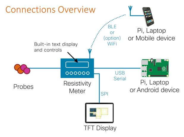
    This is a rough sketch of some (not all) of the connectivity methods and how they might be used:

    image

    GPS expansion will be feasible by plugging the GPS module directly into the Pi, but it might become unnecessary, since there's the possibility of either sending GPS position from a phone (via Bluetooth or BLE) or sending the measurements into the phone. The only limitation is what's coded, since the underlying hardware covers lots of popular interfaces (USB, BLE, etc). There's memory on-board too, so in theory the data is reliably stored and the SD Card is for transferring stuff (edit: there's no SD card option, it's unnecessary since there are better wired and wireless options) . Also, if it's more comfortable for someone to analyze remotely from a larger computer, then any captured data can be sent in real-time from the phone - assuming it is coded!

    • Cancel
    • Vote Up +5 Vote Down
    • Sign in to reply
    • Cancel
  • michaelkellett
    michaelkellett over 5 years ago in reply to shabaz

    I wasn't thinking of supporting an SD card interface, unless others feel this to be essential:


    1) The low power Cortex M4 processor doesn't support it

    2) If we change processor to one that does we'll need probably to go to 144 pin chip

    3) The code to support SD card is complicated

    4) You have to support a full on disc filing system

    5) Could use a support chip as Gene suggested but it will use a lot of pins.

    6) All the above if we support USB OTG except the low power processor is OK with it.


    Probably not clear on my original block diagram that the options in the dotted processor outline might need to use a different processor.


    On the other hand if we go for a more powerful processor we do get the benefit of faster processing all the time. The H7s support

    dual voltage SD card at up to 104MHz - there is some free software from ST which seems to support FAT.

    An H7 will burn more power speed for speed and about 300mW more at full (400MHz) speed.


    See ST app note AN5200


    I'm agnostic on this one - I've got quite used to STM32H7s now image


    MK

    • Cancel
    • Vote Up +5 Vote Down
    • Sign in to reply
    • Cancel
  • BigG
    BigG over 5 years ago

    This is a fascinating open source project.


    I'm rather curious as to whether there are ways to improve the 1m or 0.5 meter sampling distance accuracy, in terms of achieving repeatability. As in, say you need to return and remeasure a segment within the 20m x 20m grid. What steps are required to achieve this.


    My presumption is that GPS might not give you the fine granularity required, or maybe it does (I'm no expert). So, I'm wondering if Bluetooth 5.1 or UltraWideBand (UWB) tech could assist here. Just a thought.

    • Cancel
    • Vote Up +5 Vote Down
    • Sign in to reply
    • Cancel
  • shabaz
    shabaz over 5 years ago in reply to michaelkellett

    Oh, I see.. sorry I'd blindly copied that and not noticed the dashed line. I'll remove it, I cannot see it ever being needed, since there's more flexible wireless and wired options to transfer data.

    • Cancel
    • Vote Up +3 Vote Down
    • Sign in to reply
    • Cancel
<>
element14 Community

element14 is the first online community specifically for engineers. Connect with your peers and get expert answers to your questions.

  • Members
  • Learn
  • Technologies
  • Challenges & Projects
  • Products
  • Store
  • About Us
  • Feedback & Support
  • FAQs
  • Terms of Use
  • Privacy Policy
  • Legal and Copyright Notices
  • Sitemap
  • Cookies

An Avnet Company © 2025 Premier Farnell Limited. All Rights Reserved.

Premier Farnell Ltd, registered in England and Wales (no 00876412), registered office: Farnell House, Forge Lane, Leeds LS12 2NE.

ICP 备案号 10220084.

Follow element14

  • X
  • Facebook
  • linkedin
  • YouTube