element14 Community
element14 Community
    Register Log In
  • Site
  • Search
  • Log In Register
  • About Us
  • Community Hub
    Community Hub
    • What's New on element14
    • Feedback and Support
    • Benefits of Membership
    • Personal Blogs
    • Members Area
    • Achievement Levels
  • Learn
    Learn
    • Ask an Expert
    • eBooks
    • element14 presents
    • Learning Center
    • Tech Spotlight
    • STEM Academy
    • Webinars, Training and Events
    • Learning Groups
  • Technologies
    Technologies
    • 3D Printing
    • FPGA
    • Industrial Automation
    • Internet of Things
    • Power & Energy
    • Sensors
    • Technology Groups
  • Challenges & Projects
    Challenges & Projects
    • Design Challenges
    • element14 presents Projects
    • Project14
    • Arduino Projects
    • Raspberry Pi Projects
    • Project Groups
  • Products
    Products
    • Arduino
    • Avnet Boards Community
    • Dev Tools
    • Manufacturers
    • Multicomp Pro
    • Product Groups
    • Raspberry Pi
    • RoadTests & Reviews
  • Store
    Store
    • Visit Your Store
    • Choose another store...
      • Europe
      •  Austria (German)
      •  Belgium (Dutch, French)
      •  Bulgaria (Bulgarian)
      •  Czech Republic (Czech)
      •  Denmark (Danish)
      •  Estonia (Estonian)
      •  Finland (Finnish)
      •  France (French)
      •  Germany (German)
      •  Hungary (Hungarian)
      •  Ireland
      •  Israel
      •  Italy (Italian)
      •  Latvia (Latvian)
      •  
      •  Lithuania (Lithuanian)
      •  Netherlands (Dutch)
      •  Norway (Norwegian)
      •  Poland (Polish)
      •  Portugal (Portuguese)
      •  Romania (Romanian)
      •  Russia (Russian)
      •  Slovakia (Slovak)
      •  Slovenia (Slovenian)
      •  Spain (Spanish)
      •  Sweden (Swedish)
      •  Switzerland(German, French)
      •  Turkey (Turkish)
      •  United Kingdom
      • Asia Pacific
      •  Australia
      •  China
      •  Hong Kong
      •  India
      •  Korea (Korean)
      •  Malaysia
      •  New Zealand
      •  Philippines
      •  Singapore
      •  Taiwan
      •  Thailand (Thai)
      • Americas
      •  Brazil (Portuguese)
      •  Canada
      •  Mexico (Spanish)
      •  United States
      Can't find the country/region you're looking for? Visit our export site or find a local distributor.
  • Translate
  • Profile
  • Settings
Power & Energy
  • Technologies
  • More
Power & Energy
Forum Empty Capacitor Bank
  • Blog
  • Forum
  • Quiz
  • Documents
  • Polls
  • Events
  • Mentions
  • Sub-Groups
  • Tags
  • More
  • Cancel
  • New
Actions
  • Share
  • More
  • Cancel
Forum Thread Details
  • State Not Answered
  • Replies 16 replies
  • Subscribers 287 subscribers
  • Views 1150 views
  • Users 0 members are here
Related

Empty Capacitor Bank

Former Member
Former Member over 11 years ago

Hello everyone. I am in the process of building a coil gun, and I am having problems with my capacitor charger. Would a voltage multiplier circuit serve the same purpose as a capacitor bank charger? I have a schematic for a capacitor bank charger, and it is not functioning... If you know of a charging circuit that works, it would be great if you could share it with me.

Thanks,

     Conor

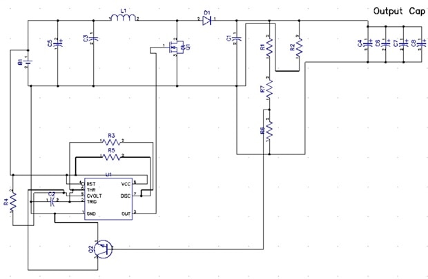
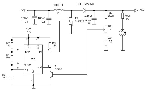
This the link to the Schematic I originally used for the charger.

http://uzzors2k.4hv.org/projectfiles/450vboostconverter/boost_converter%2012v.gif

  • Sign in to reply
  • Cancel
  • dougw
    0 dougw over 11 years ago in reply to Former Member

    It should work the same but it has better specifications, so if some marginal design depends on poor performance, this part might perform too well..

    • Cancel
    • Vote Up 0 Vote Down
    • Sign in to reply
    • Verify Answer
    • Cancel
  • qmiteam
    0 qmiteam over 11 years ago

    This circuit has many issues and is not well suited to charging a large capacitor bank,  A voltage multiplier requires an AC input, so in the purpose of a coilgun, I imagine you ultimately want to power this from batteries, it would require an extra conversion.  You are on the right track with a DC-DC converter.  Your topology is of the boost type converter, but you would realize better performance from a flyback type (transformer) converter and this would isolate the power components (mosfet) from the high voltage side.  Also if the bank is large, use a soft start ramp up to reduce the inrush currents as the capacitor bank will behave almost as a dead short across the output when it is discharged.  If you are looking for a quick dirty way to just charge the bank to test the circuit, just salvage a photoflash unit (even from disposable cameras) as these are typically designed for 330V output and most use a cheaply made flyback converter.  Be warned this is not a good long term solution as they are designed for a short duty cycle (especially the ones in disposable cameras), and the power components are not designed to operate more than a few seconds at a time before a cooldown period.  But if you are just trying to test a concept....

    • Cancel
    • Vote Up 0 Vote Down
    • Sign in to reply
    • Verify Answer
    • Cancel
  • Former Member
    0 Former Member over 10 years ago in reply to qmiteam

    Alright, so what your saying is that the current design that I have does not work. I am charging the capacitors from a 9V battery power supply. I am very new to this hobby so I am very ignorant when it comes to certain converters and such, I am appreciating all the help. Ill draw up a new schematic and I would be grateful for another proofread.

    • Cancel
    • Vote Up 0 Vote Down
    • Sign in to reply
    • Verify Answer
    • Cancel
  • Former Member
    0 Former Member over 10 years ago in reply to qmiteam

    This is what I have come up with...

    image

    I Do not have any capacitor values on this because the program was for designing PCB Boards, I used this schematic as a reference.

    image

    • Cancel
    • Vote Up 0 Vote Down
    • Sign in to reply
    • Verify Answer
    • Cancel
  • Former Member
    0 Former Member over 10 years ago in reply to Former Member

    Q1 is an IRF730, Q2 is am MPSA44

    Ill use the same resistor capacitor and a similar Diode unless stated otherwise.

    I am not familiar with the symbol coming off of R7

    Also, in the reference schematic, there is T1 going directly into R5, I routed T1 below R5 in my schematic, is this correct?

    • Cancel
    • Vote Up 0 Vote Down
    • Sign in to reply
    • Verify Answer
    • Cancel
  • michaelkellett
    0 michaelkellett over 10 years ago in reply to Former Member

    Before building this I very strongly recommend that you simulate it. LTSpice is a free download and can easily cope with this circuit. Unless you are going to do a LOT of maths you can't tell what it will do unless you simulate. It's a lot cheaper and quicker than building it.


    MK

    • Cancel
    • Vote Up 0 Vote Down
    • Sign in to reply
    • Verify Answer
    • Cancel
<
element14 Community

element14 is the first online community specifically for engineers. Connect with your peers and get expert answers to your questions.

  • Members
  • Learn
  • Technologies
  • Challenges & Projects
  • Products
  • Store
  • About Us
  • Feedback & Support
  • FAQs
  • Terms of Use
  • Privacy Policy
  • Legal and Copyright Notices
  • Sitemap
  • Cookies

An Avnet Company © 2025 Premier Farnell Limited. All Rights Reserved.

Premier Farnell Ltd, registered in England and Wales (no 00876412), registered office: Farnell House, Forge Lane, Leeds LS12 2NE.

ICP 备案号 10220084.

Follow element14

  • X
  • Facebook
  • linkedin
  • YouTube