


Hi,
I'm designing an open-source USB 3.x Type-C (KVM) Switch, and I'm looking for some feedback on the design I came up with.
The USB 3.x Type-C (KVM) Switch will be the modern version of a traditional KVM Switch, meant to work with modern USB Type-C capable monitors like the Dell P2720DC.
These monitors can use a single USB Type-C cable to carry a high resolution video signal, USB data signals and are also capable of charging connected devices using USB Power Delivery.
Usually there is just a single USB Type-C input available, and as I have multiple devices I started looking for USB Type-C switches. It turned out there are not too many options available, and all are like super expensive ($100+). So, I decided to try to design one.
The device will have the following features:
- two USB 3.x Type-C Input ports
- one USB 3.x Type-C Output port
- switching of all four USB 3.x SuperSpeed differential pairs
- switching of the USB 2.x HighSpeed differential pair
- switching of the Configuration (CC) and Sideband use (SBU) channels
- USB Power Delivery pass-through up to the full power range 20V @ 5A
- reasonable cost
In terms of design, I think we should have the following sections:
- USB 3.x SuperSpeed differential pair switching
- with high bandwidth (5-10 GHz) analog multiplexers / de-multiplexers designed for differential signals
- best candidates are Texas Instruments HD3SS3212, or ON Semi FUSB340TMX
- biasing on the differential lines may be needed
- USB 2.x HighSpeed differential switching
- can be done using IC-s designed for USB 2.0 switching
- there are lot of options, ex. Texas Instruments TS3USB221 - I will probably choose one based on price and availability
- switching of auxiliary Configuration (CC) and Sideband use (SBU) signals
- these are supposed to be low speed and voltage signals
- can be switched with any analog multiplexers / de-multiplexers, ex. Texas Instruments TS3A44159
- switching of the VBus power signal
- this is trickier as with USB Power Delivery the voltage can go up to 20V @ 5A, and the power can be provided either by the input or output port
- can be done using high power photocouplers, like the Toshiba TLP3547
- the disadvantage is that this high power photocouplers are super expensive - probably it can be done easier and I'm just over-complicating it (?)
- 3.3V power supply
- combine the VBus signal of the three USB Type-C connectors with diodes
- use a LDO regulator to generate the 3.3V power rail
- Microcontroller and I/O
- something Arduino compatible, maybe an SMT32
- not yet included in the schematics
- control by a button, and feedback by one or more LED-s
Here is the first version of the schematic I came up with:
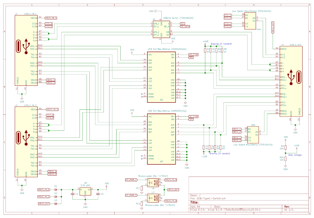
The PCB probably will be a 4-layer one. I also thought to try (just for fun) a 2-layer PCB with a shielding provided by an aluminium casing.
So, I wanted to ask what do you think about this design?
Do you see anything terrible wrong with it? What are the parts of the design that can be improved?
Thanks,
Attila


