Take the Poll | Join our Discussion
sponsored by

High Temperatures in Tiny Spaces
As electronic devices become increasingly compact, the surface mount circuitry inside becomes smaller and more tightly packed. Substantial heat generation can be caused by the higher density of components that are packed into tiny enclosures, as well as the faster clock speeds of modern devices. Thermal management is required to ensure reliable performance.
Thermal jumpers enable designers to tackle thermal issues by connecting heat-generating components to ground planes or heat sinks, dissipating the heat. Thermal jumpers are electrically isolated, making them suitable for cooling components that cannot be grounded. Before jumping into thermal jumpers, let’s briefly go over some other ways to cool surface mount devices (SMDs).
Different Ways to Cool Surface Mount Devices
Natural Convection
For PCBs that do not require a great deal of heat dissipation, natural convection is usually sufficient. With natural convection, heat is transferred from the PCB to the surrounding air, with the heat first flowing through the alumina substrate, the metal chip contact, the solder joint, and finally across the board, typically constructed of FR4, a glass-reinforced epoxy resin laminate, with a thin layer of copper foil laminated to one or both sides. Some heat will be dissipated through electronic components. Additional heat is dissipated with the resistance of electrical connections, vias, and copper traces.
Natural convection cooling is widely used for PCBs with low to medium power density (102 to 104 W/m2). If sufficient cooling can be maintained with this technique, natural convection cooling has advantages, such as lower costs and noise, due to fans not being required. However, designs with excessive heat require a cooling solution.
|
What Is Thermal Resistance? Thermal resistance is the measurement of how much a material or object resists heat flow. The lower the thermal resistance, the faster heat can transfer through, making it easier to cool. Thermal resistance is calculated as:  Where Δx is the thickness of the material (m), k is the material’s thermal conductivity factor (W/K*m), and A is the cross sectional area (m2). |
Wide Copper Traces
Increasing the width of copper traces provides a larger surface area that reduces thermal resistance and helps in heat dissipation. PCBs used in high power applications typically use wide copper traces.
Heat Sinks
A heat sink is a piece of thermally conductive material with a large surface area, usually attached directly to heat generating components with thermal paste. Heat is transferred from the component to the heat sink, and then to the surrounding air.
Thermal Vias
Thermal vias are a popular technique for removing heat in SMD designs. Thermal vias are heat-conducting holes placed directly under the component that needs to be cooled. They have the benefit of increasing the copper's area and mass, reducing thermal resistance, and pulling heat away from critical electronic components through conduction. Placing thermal vias as close to a heat source as possible reduces thermal resistance and improves heat dissipation.
Cooling Fans
Cooling fans increase air flow, helping to cool components more quickly. Cooling fans are effective solutions, and are ubiquitous in devices that generate excessive heat, such as GPUs and high current power supplies. Cooling fans add a significant cost, however, and are less reliable than solutions without moving parts. Cooling fans also add size and weight.
Heat Pipes
Heat pipes are pipes that contain a fluid, such as water, acetone, nitrogen, or ammonia, that absorbs heat. As the liquid heats up, it changes phase, converting to a vapor. The vapor then passes through a condenser, which changes the vapor back to liquid form, restarting the cycle.
Integrated Cooling Methods
Combining two or more cooling methods together allows higher heat conductivity coefficients than using just a single technique. Vias underneath a component can dissipate heat from the bottom, while a heat sink can be attached to the top surface. The heat sink should be connected to the component with thermal paste, maximizing thermal conductivity. A cooling fan increases air flow around the heat sink, allowing more heat to be transferred to the surrounding air.
Thermal Modeling Software
To help with the design of the PCB and cooling, thermal modeling software can be used to analyze the design and locate hotspots. A thermal analysis establishes the behavior of a PCB and its components at different temperatures and conditions. This gives an accurate estimate of where heat is generated, dissipated, and transferred within the circuit. Thermal modeling allows the designer to more effectively design a cooling solution for a given circuit.
What Is a Thermal Jumper?
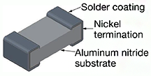
Thermal Jumpers are surface mount chips with two principal functions: to provide a thermally conductive pathway to a heat sink or ground plane, and to maintain electrical isolation between the component and the heat sink or ground plane. Figure 1 depicts the construction of a thermal jumper.

Figure 1: Construction of Thermal Jumper
Source: Vishay
Thermal jumpers often use aluminum nitride (AlN) for heat transfer. Aluminum nitride has five times the thermal conductivity of alumina (Al2O3). It is also an insulator, having a resistance of >999 MΩ, and has a low capacitance that makes it well-suited for high frequency and ladder applications.
The Importance of Electrical Isolation
Some components require cooling, but cannot be connected to ground. For example, the backplate of a typical MOSFET is connected to drain, and thus has a voltage present. Any type of connection to ground would cause unwanted effects in the circuit.
Figure 2 illustrates a MOSFET connected to a mounting pad, which is connected to a heat sink through a thermal jumper. The thermal jumper transfers the heat to the heat sink, where it can be dissipated to the surrounding air. Electricity is not transferred between the MOSFET and heat sink, because the thermal jumper acts as an electrical insulator between the two. The voltage of the heat sink (likely 0V) does not affect the MOSFET.

Figure 2: Typical application using a thermal jumper
Vishay ThermaWickTM Thermal Jumpers
Vishay Intertechnology’s ThermaWickTM THJP series is a surface mount thermal jumper that provides a thermally conductive pathway to a ground plane or heat sink, while maintaining electrical isolation. The ThermaWickTM thermal jumper can increase the power handling capability of connected components or extend their life under existing conditions, while maintaining a neutral potential to the heatsink or chassis. ThermaWickTM thermal jumpers are constructed with AlN substrates and available in tin-lead (SnPb) and lead (Pb)-free (lead free) wraparound termination styles.
The AlN substrate has a high 170W/m°K thermal conductivity and can reduce the temperature of connected components by over 25%. Overall circuit reliability improves through the protection of adjacent devices from thermal loads.
The THJP's low capacitance of 0.07 pF makes it suitable for high frequency and thermal ladder applications. ThermaWickTM thermal jumpers can be used in power supplies and converters, RF amplifiers, synthesizers, pin and laser diodes, and filters for industrial and telecommunications applications.

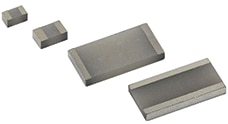
Figure 3: THJP-series thermal jumper chips
The THJP series is available in six case sizes, from 0603 to 2512, with custom sizes available. The 0612 and 1225 cases feature long side terminations for additional heat transferring capability. The following table illustrates the different features across the family.
|
Case size |
0603 |
0612 |
0805 |
1206 |
1225 |
2512 |
|
Thermal Resistance (°C/W) |
14 |
4 |
13 |
15 |
4 |
15 |
|
Thermal Conductance (mW/°C) |
70 |
259 |
77 |
65 |
259 |
65 |
|
Capacitance (pF) |
0.07 |
0.26 |
0.15 |
0.07 |
0.26 |
0.07 |
|
Dielectric Withstanding Voltage kVAC, RMS (60 Hz) |
> 1.5 |
> 1.5 |
> 1.5 |
> 1.5 |
> 1.5 |
> 1.5 |
Table 1: THJP series surface-mount thermal jumper features
Heat Transfer Demonstration
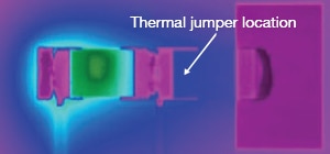
To demonstrate the heat transfer capabilities of ThermaWickTM thermal jumpers, Vishay used a FLIR SC645 thermal imaging system to measure the temperature of an SMD ceramic resistor with and without a connection to a heat sink via a thermal jumper. The resistor was mounted to an FR4 test card designed with a 25 mm x 19 mm copper heat sink. Power was supplied to the device and the surface temperature of the resistor was stabilized at 150 °C. The device was then retested at the same power level with the resistor connected to the heat sink via thermal jumper.

Figure 4: Ceramic Resistor Chip without Thermal Jumper (149.8 °C)

Figure 5: Ceramic Chip Resistor with Thermal Jumper (95.5 °C)
A large decrease in maximum temperature at the center of the lacquer surface of the resistor can be observed. The area surrounding the resistor, including the solder joints, also have a marked decrease in temperature. The demonstration showed the THJP1206 thermal jumper reducing the surface temperature of the SMD resistor by 36%.
Conclusion
Most electrical components generate heat, which in the modern world of tiny surface mount components cannot be removed so easily. Because excess heat can damage or reduce the life of electrical components, cooling solutions must be integrated into the circuit. One such cooling solution is the thermal jumper, such as the ThermaWickTM thermal jumpers from Vishay InterTechnology. Thermal jumpers provide a pathway to a heat sink or ground plane that effectively transfers heat, but not electricity. They are well-suited for cooling devices that may require electrical isolation.
