
Energy storage is now considered an integral component of electrical power generation, including alternative energy, uninterruptible power supply (UPS) applications, microgrids, and many more. Its ability to function as a flexible power source, balancing supply and demand, and bridging the gap between energy generation and consumption contributes to the important role it plays in power technology today. But its benefits don't stop there. Energy storage systems can increase the efficiency of non-renewable energy sources. Electrochemical devices designed for energy storage are some of the most important and durable innovations among all energy storage technologies. Energy storage is even a crucial component of energy harvesting applications, due to the discontinuous nature of harvested ambient energy and the variability of energy consumption. Although energy can be stored in many forms (e.g., mechanical, thermal, or chemical).
This learning module focuses on electrical storage and examines two common electrical storage technologies – batteries and electrochemical supercapacitors – and their types, characteristics, and associated electronics.
Related Components | Test Your Knowledge 
2. Objectives
Upon completion of this module, you will be able to:
- Recognize the benefits of electrical energy storage
- Describe the different types of electrical storage technologies available
- Discuss storage battery and supercapacitor technologies, as well as their associated electronics
- List some of the safety and regulatory standards for batteries
3. Basic Concepts
While this learning module focuses on the major types of electrical energy storage, let us discuss briefly the main types of energy storage technologies to put electrical energy storage into perspective, as well as provide a general background of energy storage technology.
3.1 Energy Storage Technologies
Energy storage technology has leveraged many different sources of energy. Table 1 summarizes some of the most common energy storage technologies in use or undergoing research today.
| Kinetic Energy | Potential Energy | ||||
| Thermal Technology | Electrical Technology | Mechanical Technology | Electrical Technology | Chemical Technology | |
| Hot/Cold Water | Super-Capacitor | Flywheels | Pump Hydro | Lithium Ion | Hydrogen |
| Molten Salt | Magnetic Super-Conductor | Compressed Air | Lead Acid | Synthetic Natural Gas | |
| Phase Change | Redox Flow | ||||
| Sodium Sulphur | |||||
Table 1: A Summary of Energy Storage Technologies
On the micro level, current developments in electrical energy storage technologies have enabled a new generation of Internet of Things (IoT) sensors and devices, and a proliferation of hand-held, portable devices. On the macro level, new technologies are providing viable options for handling fluctuations from renewable power sources on regional and national power grids (e.g., solar and wind), as well as making all-electric vehicles more affordable, and thus more widely available for both individual and commercial users. The following list briefly covers the energy storage technologies covered in Table 1.
- Compressed Air: a method of energy storage that uses compressed air, which is stored in underground cavities.
- Electrochemical: a method used to store electricity in a chemical form. This category of energy storage includes batteries, fuel cells, supercapacitors, etc.
- Electrostatic: a method of storing energy via the potential energy stored in charges of an electric field. A capacitor is the most common type of electrostatic energy storage.
- Flywheels: a method of kinetic energy storage as rotational energy.
- Hydrogen: using electrolysis, water is split into its hydrogen and oxygen, where hydrogen serves as an energy storage medium.
- Molten Salt: used in solar thermal energy storage, molten salt is circulated through a heat exchanger and functions as a heat transfer fluid as well as a thermal energy storage medium.
- Pumped Hydro-Power: a type of bulk energy storage where two reservoirs located at different heights are used to create gravitational potential energy. Surplus energy is used to pump water to the upper level reservoir. Water is released to the lower level to drive a turbine that generates electricity.
- Redox Flow: a type of electrochemical energy storage, based on oxidation and reduction between two active materials. A redox flow battery contains the electrolyte, including the active materials, separated by a membrane in external tanks.
- Sodium Sulphur: a method of battery energy storage, operated at very high temperatures (300 to 350 °C), using molten sulfur as the positive electrode and molten sodium as the negative electrode. The electrodes are separated by a solid ceramic, sodium alumina, which also serves as the electrolyte.
- Supercapacitors: a special type of capacitor that has a relatively high energy density compared to the storage capacities of conventional capacitors.
- Thermal: a method of heat energy storage.
3.2 Low-Power Modes
A relationship exists between energy consumption and energy storage: by lowering consumption, stored energy is extended. A good example of this is in the low-power modes of portable electronic devices. A low-power mode is a technique for maximizing the length of time a portable device can be used before recharging is necessary, especially when the device is turned off. When in a low-power mode, portions of the electronics are disabled or scaled back to minimize the battery discharge rate. Unessential devices are forced into standby, disabled, or powered-off completely. Clock rates are often reduced to optimize the performance for the basic tasks being performed. Low-power modes have gained popularity in many types of electronics (e.g., microcontrollers). See element14 ESSENTIALS: Low-Power Microcontrollers.
4. Batteries As Energy Storage Devices
A battery is an electrochemical energy storage device that converts chemical energy into electrical energy. Examples include lithium-based batteries, nickel-based batteries, and lead-acid batteries. Both primary (i.e., non-rechargeable) and secondary (i.e., rechargeable batteries) store electricity in a chemical form. Primary cells are non-rechargeable batteries, while secondary cells are rechargeable. Battery cells are the basic unit of a battery module; interconnected battery modules form a battery pack. A battery consists of two electrodes, the anode and cathode, and a separator. The space between the electrodes is filled with ionically conductive liquid electrolyte: it can conduct ions but not electrons. Anions or negative ions migrate towards the anode through the electrolyte; cations or positive ions migrate towards the cathode. A difference in potential is created between the electrodes.
4.1 Oxidation-Reduction (Redox) Reactions
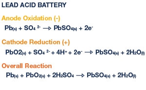
Figure 1: Oxidation-Reduction Reactions in a Lead-Acid Battery
Oxidation-reduction reactions occur at the electrolyte-electrode interface. The oxidation half reaction yields electrons at the anode, removing electrons from the electrolyte for use in the external circuit; the reduction half reaction gets electrons at the cathode, giving electrons to the electrolyte. When an electrical load of an external circuit is connected across the anode and cathode, during battery discharge, electrons at the anode now have a return path to the cathode but through the load.
4.2 Types of Rechargeable Batteries
In 1859, Gaston Planté is reported to have invented the first lead-acid rechargeable battery. Lead-acid batteries continue to be used in products as common as automobiles, appliances, and tools. But they are also used in products and equipment found in hospitals and phone companies, to name a few. But for electronic products, Lithium- or Nickel-based batteries are the batteries of choice. See Table 2 below for a comparison of the main types of rechargeable battery technologies.
| TECHNOLOGY/CHEMISTRY | RELATIVE COST | ENERGY DENSITY | VOLTS/CELL | ADVANTAGES | DISADVANTAGES |
| Pb-Acid Lead Acid |
Low 56-145 $/kWh |
Low 0.11-0.14 MJ/kg |
1.75 - 2.23V | Rugged, widely used, wide temperature range | Limited discharge, risk of explosion, poor environmental impact |
| Li-Ion Lithium Ion Several Chemistries |
High e.g. LiCoO2 356 $/kWh |
High 0.70 MJ/kg |
2.5 - 4.2V | High energy/mass ration i.e., low weight, low self-discharge | More electronics required for safety, regulatory restrictions for travel |
| Li-Pol Lithium Polymer Several Chemistries |
High 356 $/kWh |
High 0.54 MJ/kg |
2.5 - 4.2V | Can be ultra-thin (~1mm), mold to any shape, low self-discharge rate | More electronics required for safety |
| NiCd Nickel Cadmium |
High >400 $/kWh |
Low 0.11 MJ/kg |
0.9 - 1.3V | Quick charge/discharge, rugged high number of charge cycles (>1000) | Poor environmental impact, Memory effect, High self-discharge |
| NiMH Nickel Metal Hydride |
Medium 297 $/kWh |
Medium 0.36 MJ/kg |
0.9 - 1.3V | Decreased memory effect, environmentally friendly | Lower number of charge cycles, High self-discharge |
Table 2: Comparison of Rechargeable Battery Technologies
NiMH batteries have gained market share from NiCd batteries because they are much friendlier for the environment, and have some performance advantages as well. Note that NiCd has been banned in the EU for most uses due to the toxicity of cadmium that can cause kidney, bone, and/or lung disease (long term exposure), according to the U.S. Department of Labor. NiCad batteries also experience the memory effect, which is the long-term effect of a battery not reaching its full charge capacity. If batteries are partially charged to the same (less than full) level repeatedly, it can become an issue over time.
NiMH batteries are not susceptible to the memory-effect problem, and the batteries can be partially charged without an issue. However, NiMH batteries can experience voltage depression. To eliminate the possibility of NiMH batteries experiencing voltage depression, manufacturers recommend an occasional, complete deep discharge of NiMH batteries followed by a full recharge.
Lithium ion batteries are now replacing lead- and nickel-based batteries in many applications. For safety reasons, Li-ion batteries need a protection circuit. Note that there are several chemistries available under the Lithium category in Table 2, including versions of both Li-Ion and Li-Polymer, which are only different in terms of their dielectric, as opposed to the materials in the anode and electrode. Li-Ion batteries have gained popularity from NiMH, due to lower costs and higher peak currents in newer models (e.g., hand tools). When setting the charger voltage, the specific chemistry will determine the maximum voltage. Refer to the battery data sheet for safe charging practices.
 |
 |
 |
 |
| 3.7V Dantona Rechargeable Battery |
3.7V Varta Rechargeable Battery |
3V Rayovac Coin Cell Battery |
3.7V Adafruit Rechargeable Battery |
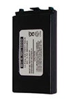
Figure 2: Batteries are now available in a variety of form factors. Here are some examples of Lithium Polymer batteries for electronics applications.
4.3 Battery Cell Configurations
Batteries can be connected in a variety of ways to target a desired voltage or increase the overall capacity of a battery storage system. Battery cells can be connected as modules, and modules can be connected as battery packs in series and/or parallel to achieve the aforementioned results. Series configuration can increase the terminal voltage, while parallel configurations can increase the capacity. When designing a battery pack that’s more than a single cell, always use the same type and size of battery to avoid the possibility of imbalances. Compared to using standard cells, a series/parallel configuration provides the benefit of greater design flexibility while achieving the target voltage and current ratings.
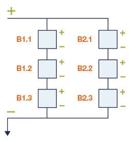
Figure 3: 3s2p battery pack configuration
Battery pack configuration is determined by a number/letter/number/letter term. The first number indicates the number of cells connected in a string and the first letter indicates how the string(s) is/are connected: “p” for parallel and “s” for series. The second number indicates the number of strings and the second letter indicates how they are connected. For example, 3S2P means 3 cells in a series string, and there are 2 strings connected in parallel. For Li-Ion batteries, this works out to a maximum voltage of 3x4.2=12.6V, and whatever the maximum discharge of the cell is, you can roughly double that (from the 2P).
Products should use battery holders that protect against batteries being inserted backwards; this is done using steering diodes. Each model cell has a certain capacity, rated in terms of Ampere-Hours (Ah). More Ah means more run time at a given load, or more load for a given run time. According to the particular chemistry, a larger battery will generally have proportionally more capacity.
4.4 Self-Discharge
Self-discharge is a battery phenomenon where internal chemical reactions reduce the stored charge of the battery without a load connected between the electrodes. Self-discharge should be factored into the battery life calculation for a given product. The battery life should be calculated using the load profile (duty cycle/maximum load versus time), as well as the self-discharge rate when inactive.
How quickly battery self-discharge occurs depends on type, SOC charging current, temperature, and more. Primary batteries use battery chemistry with much lower self-discharge rates than rechargeable batteries, since they must have an economically practical shelf life. Self-discharge tends to occur more quickly at higher temperatures. Storing batteries at lower temperatures reduces the rate of self-discharge. Self-discharge is also thought to be reduced as a passivation layer (See Glossary) develops on the electrodes.
5. Battery Management
A battery management system (BMS) ensures the optimal use of a battery in a portable device. Typically, it manages a rechargeable battery pack to ensure that it’s operating within specifications.
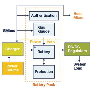
Figure 4: Block Diagram of Battery Management System (BMS)
A BMS can also manage power distribution and power consumption. It usually includes a cell voltage and balancing monitor, temperature monitor, battery authentication circuitry, real-time clock, protection circuits, and a voltage reference/regulator.
Additionally, a BMS closely monitors battery charging and discharging to avoid thermal conditions that would otherwise reduce the battery’s capacity or its lifespan.
5.1 Battery Charging
Charging a battery requires regulating both the voltage and the current, depending on the chemistry, topology, and point in the charge cycle. Thus, there is a need for special regulators, called chargers. There are both linear and switching chargers. Efficiency is more important for discharging a battery than charging, because the charging process is usually done via the power utility (i.e., wall outlet) and has no effect on stored energy in the battery of a portable device, as long as you wait until the battery is fully charged.
Based upon these requirements, designers of cost-sensitive electronics or space-limited applications with charge currents less than 1A may consider using a linear regulator (less efficient) which is adequate for charging a battery, especially if it doesn’t have to happen quickly. Chargers can be either stand-alone or controlled by a host microcontroller. Even for stand-alone devices, status can be monitored using LED outputs or over an I2C serial bus. The standard protocol for communicating with power devices over I2C is called SMBus.
 |
 |
| MAX77650EVKIT# Evaluation Kit | MCP19125 Flyback Battery Charger Eval Board |
Figure 5: Examples of Battery Charger IC Evaluation Boards. The MAX77650/MAX77651 evaluation kit evaluates various features of the MAX77650/ MAX77651, including the
SIMO buck-boost regulator, linear regulator, analog multiplexer, smart battery charger, on/off controller, and I2C interface.
The MCP19125 Flyback Battery Charger Evaluation Board is a mixed-signal low-side synchronous Pulse Width Modulation (PWM) controller, featuring individual analog PWM control loops for both current- or voltage-regulation.
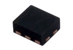
*Lithium Ion Battery Protection Device
When designing a product powered by Li-ion batteries, one must include protection circuits for high voltage during charging, low voltage during discharging, high current in both states, high temperature, and low temperature. Some rechargeable battery types are available in the same form factors as disposable batteries (primary), which presents a design challenge in terms of safety, since the system should never charge a primary cell. Because lithium is a very reactive compound that can burst into flames, safety measures need to be included in the battery pack, such as safety ICs or other onboard control chips to manage the temperature and prevent a complete discharge.
*Figure 6: Example of a Battery Protection IC. The AP9234L offers single-chip protection for a 1-cell Li+ rechargeable battery pack application. It provides battery protection features that can turn off the N-Channel MOSFET by detecting overcharge voltage/current, overdischarge voltage/current, or load short circuit.
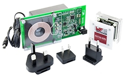
*760 308 MP Wireless Power TR & RX EVM
One of the latest trends in the portable devices industry is wireless charging. The underlying principle behind wireless charging is Faraday’s law of induced voltage, commonly used in motors and transformers. The wireless charging transmitter is powered by an input typically derived from a USB port or an AC/DC power adapter. A switched transistor bridge drives a coil and series capacitor. The transmitter has a coil to transfer power by electromagnetic induction. The induced power is coupled to the wireless power receiver, which has a similar coil to collect the incoming power. The receiver rectifies the power, and also filters the power and then applies it to the battery for charging, either through a linear stage or a switching regulator. The receiver can tell the transmitter to adjust the charging current or voltage, and also to stop transmitting power when end of charge is indicated. For more information on wireless charging, refer to the industry standard for wireless power transfer called Qi.
*Figure 7: The 760 308 MP Wireless Power Design Kit is based on the Qi specification 1.2.2 and supports the Extended Power Profile (EPP) from the Wireless Power Consortium (WPC). This kit demonstrates the advantages of wireless power and gives developers the opportunity to test and integrate a wireless power solution into their application.
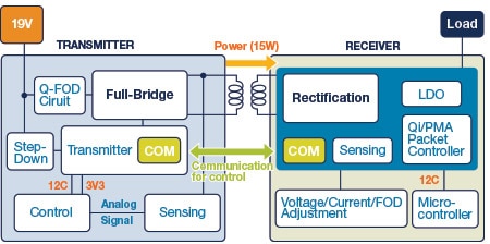
Figure 8: Block Diagram of a Wireless Charging Transmitter/Receiver System
5.2 The “C” Rate
The charge and discharge rate, or the “C” rate, is often expressed as nC, where n is the charge/discharge current divided by the ampere-hour (Ah) capacity of the cell. For example, a 0.1 C discharge rate for a battery rated at 2 Ah is equivalent to 0.2 A of discharge current. And a 500 mAh battery that’s discharged at 100 mA, is discharged at the 0.2 C rate. A battery rated for 2 Ah discharged at 1 C (or 2 A) will operate for less than one hour. But a battery rated for 2 Ah, discharged at 0.1 C (or 200 mA) will operate for more than ten hours. The "C" rate is a convenient way to talk about battery charging for many cell sizes since the cells' response to charging will be similar if the "C" rate is the same.
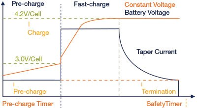
Figure 9: Current and Voltage versus Time – Li-Ion Charging Profile
5.3 Power Path Management
Power path management is the ability of a battery charger to power a system while the battery is being charged by allowing the system to draw power independent of the charging path. This avoids overloading the power source (e.g., a wall wart or USB port), and provides regulated current to the system and the battery. A key benefit of power path management is that a device with a completely discharged battery can be used as soon as it is plugged in, instead of waiting for the batteries to recharge. It also eliminates system power and charger interactions, since they have independent power paths. To illustrate power path management, please refer to Figure 10.
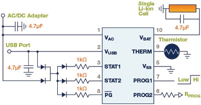
Figure 10: Schematic Diagram of the MCP73837, an integrated, linear Li-Ion/Li-Polymer battery charger with autonomous power source selection
 |
 |
| MCP73837/8 Microchip Battery Charge Management Controller |
MCP73837-FCI/MF Microchip Battery Charger |
Figure 11: Examples of devices that support power path management (Microchip: MCP73837)
The MCP73837 is a fully integrated linear Li-Ion/Li-Polymer battery charger with autonomous power source selection. It can automatically select the USB port or AC adapter as the power source for the system. The host microcontroller can select from two preset maximum charge current rates of 100 mA (low-power USB port) or 500 mA (high-power USB port). With an AC adapter providing power to the system, an external resistor sets the magnitude of the system or charge current up to a maximum of 1A.
5.4 Cell Balancing
Cell balancing is a method of correcting cell imbalances caused by manufacturing variations or other changes in similarly rated battery cells. Battery systems that have cells connected in series often run into this problem. Needless to say, the impact of cell imbalance on performance and battery life is clearly undesirable.
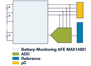
Figure 12: The MAX14921 is a high-accuracy battery-measurement analog front-end (AFE) used for cell balancing and battery-measurement applications.
There are two ways to balance the cells: passive and active. The easiest approach is to equalize the cell voltages. Active cell balancing overcomes the energy loss of the passive method by using capacitive or inductive charge storage by delivering energy where it is needed.
5.5 Battery Authentication
There are a number of reasons why a replaceable, battery-powered product would require battery authentication. Safety is perhaps the primary reason, especially for products using Li-Ion batteries. Other reasons may include service reliability, quality control, and counterfeit protection, to name a few. In the past, battery replacements used form factor authentication (i.e. battery casing and connectors). Unfortunately, this type of authentication can be defeated easily in situations where a third party can produce exact replicas.
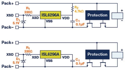
Figure 13: Example of an Authentication Device. FlexiHash for Battery Authentication
Adding simple and effective authentication technology to a portable device enables the ability to validate and verify that battery packs come from an approved source. Authentication chips use hashing or security algorithms just like encryption devices do, which are nearly mathematically impossible to “guess” the valid response to a challenge.
5.6 Voltage Regulation
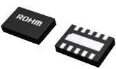
Very few systems can use battery voltage without regulation due to the wide range of voltages the battery produces over its discharge cycle. Thus, there is a need for efficient DC/DC power conversion in the form of a linear regulator, or for better efficiency, a switching regulator.
In selecting the requirements for the regulator, both the minimum and maximum battery pack voltages must be considered. Remember, the nominal battery voltage is not very helpful. There are now solutions on the market which are very efficient even at low loads, as well as regulators which work down to very low voltages consistent with single cell batteries.
 |
 |
| ROHM Semiconductor | Synchronous Boost DC/DC Converter Eval Board |
Figure 14: Example of Battery-driven Voltage Regulator with EV Kit (ROHM Semiconductor: Synchronous Boost DD/DC Converter BU33UV7NUX)
5.7 Isolation Transformers
Unlike internal combustion engine vehicles, electric vehicles (EV) depend on a more complex energy storage system that requires sophisticated battery monitoring in order to provide efficient and safe performance. For high voltage applications, typical for electric vehicle drivetrains, modular battery packs are distributed throughout the vehicle to optimize weight distribution and make maximum use of available space.
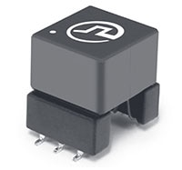
Figure 15: Pulse Electronics PH9185 is a high isolation power supply transformer driver. It's intended to operate in a fixed duty cycle Push Pull topology. A typical implementation would be an isolated RS-485/RS-232 power supply driver circuit.
Yet the biggest challenge in battery monitoring is ensuring that each battery pack communicates with the central processor so the multiple packs can operate as a single unit. Unfortunately, due to inverters, actuators, semiconductor switches, relays and other electromagnetic interference (EMI) sources within EVs, the BMS works in an electrically noisy environment. Thus, data communication links need isolation and EMI suppression that provide sufficient noise rejection.
In large battery pack applications with daisy chain connections, the high number of cells connected in series can generate greater voltage potential differences, which demand a higher level of component-to-component isolation. In these applications, serial communication links between boards need to be isolated by transformer coupling (Figure 15).
6. Battery Fuel Gauge Technology
Battery fuel gauges provide an estimate of the charge remaining in a battery. Simple battery status indicators might consist of a 5-line LCD bar graph on a low-cost device; more sophisticated visual indicators provide an estimate of operating time remaining as well as periodic battery alerts.
Early fuel gauges used coulomb counting technology to estimate the amount of charge used by the device. This would be subtracted from the battery total charge to provide an indication of remaining charge. Coulomb counting requires that the power path current be measured, which requires a sense resistor in the output path. This sense resistor consumes a continuous amount of power while the device is in operation. This technique is still in use today, although it’s usually incorporated into proprietary algorithms to provide more accurate results.
Another way to monitor the state of charge of a battery is to measure the open circuit voltage (OCV) of the battery. In most battery chemistries, the OCV is related to the state of its charge. As a simple visualization, when a battery is fully charged its OCV is generally at its maximum. As the battery charge decreases, the voltage decreases. The decrease is usually non-linear and can be dependent on temperature. To obtain an accurate state of charge using the OCV requires characterization of the battery. To obtain accurate results over time, temperature algorithms based on battery usage testing can be applied. One advantage of using OCV to estimate the state of charge is that a current sense resistor is not required in the power path, reducing the power consumption.
For Li-Ion and Li-Po batteries, battery fuel gauging is complicated by the fact that the discharge curve is very flat for most of the discharge cycle. Refer to the figures 16 and 17 below.
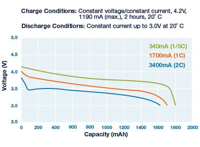
Figure 16: Li-Ion Discharge Curves for Various Loads
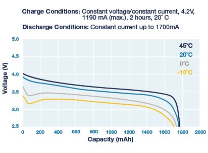
Figure 17: Li-Ion Discharge Curves for Various Temperatures
Notice that the battery voltage is a function of load, temperature, and remaining capacity, with the curve changing over time. Keep in mind these aren't the only factors that change battery voltage. The series resistance of a battery increases over time, leading to lower output voltages at any given load. This can be a real issue with coin cell batteries which have >10 Ohms series resistance even when new. (For example, the peak current when a wireless device transmits can be 50mA, at 14 Ohms, which decreases the output of a 3V coin cell to 2.3V.)

Figure 18: The MAX17055G/MAX17055X EV kits evaluate the stand-alone ModelGauge m5 host-side fuel gauge IC for lithium-ion (Li+) batteries in handheld and portable equipment.
Often there is no compensation for cell aging in battery fuel gauges. As cells age, they have higher series resistance, resulting in a decrease in output voltage under increasing load. Thus, you will not utilize the full capacity of the battery, resulting in less run time. This limits the effectiveness of a near-empty warning from the fuel gauge. If a fuel gauge is not accurate, it can have a negative impact on the run time, especially in systems which are designed to power down automatically when a certain state of charge is reached. An example of an accurate battery fuel gauge is the Maxim Integrated’s ModelGauge battery fuel gauge IC. Refer to Figure 18.
The ModelGauge m5 algorithm has enhancements that provide higher accuracy. It contains an age forecasting algorithm called Cycle+ to predict when the battery will start losing capacity due to age and use. It also has a converge-to-empty algorithm that eliminates the state of charge error that occurs at near empty. In addition, it has multiple adaptive mechanisms to allow it to learn the capacity of the battery as the battery ages.
7. Battery Safety Standards
Lithium-ion batteries are widely used in portable electronic products. As mentioned earlier in this learning module, Lithium batteries can potentially be a safety hazard. There have been some reported incidents where cell phones and “hover” boards have caught fire or even hurt people. These incidents have kept the public mindful of the safety of Lithium-ion batteries. In response, testing organizations have created standards to assess the safety risks of lithium-ion batteries. Designers of products that use Lithium-Ion batteries should be familiar with the standards used to test the safety of secondary lithium batteries:
Underwriters Laboratories
- UL 1642: Lithium Batteries
- UL 1973: Batteries for Use in Light Electric Rail (LER) Applications and Stationary Applications
- UL 2054: Household and Commercial Batteries
- UL Subject 2271: Batteries For Use in Light Electric Vehicle Applications
- UL 2575: Lithium-Ion Battery Systems for Use in Electric Power Tool and Motor Operated, Heating and Lighting Appliances
- UL Subject 2580: Batteries For Use in Electric Vehicles
Institute of Electrical and Electronics Engineers
- IEEE 1625: Rechargeable Batteries for Multi-Cell Mobile Computing Devices
- IEEE 1725: Rechargeable Batteries for Cellular Telephones
National Electrical Manufacturers Association
- C18.2M: Part 2, Portable Rechargeable Cells and Batteries — Safety Standard
International Electrotechnical Commission
- IEC 62133: Secondary Cells and Batteries Containing Alkaline or Other Non-acid Electrolytes — Safety Requirements for Portable Sealed Secondary Cells, and for Batteries Made from Them, for Use in Portable Applications (Harmonized Global Standard)
Japanese Standards Association
- JIS C8714: Safety Tests for Portable Lithium-Ion Secondary Cells and Batteries For Use In Portable Electronic Applications Battery Safety Organisation
- BATSO 01: Manual for Evaluation of Energy Systems for Light Electric Vehicle (LEV) — Secondary Lithium Batteries
8. Electrochemical Supercapacitors
Electrochemical supercapacitors (also known as supercapacitors, ultracapacitors, or electrochemical double-layer capacitors) are a special type of capacitor that has a relatively high energy density compared to conventional capacitors. To date, they store as high as 10,000 Farads/1.2volt, which is 10,000 times higher than electrolytic capacitors, but deliver or accept less than half as much energy per unit time. While supercapacitors have specific energy (Wh/kg) and energy densities (Wh/l) that are approximately 10% of batteries, their power density (W/m3) is generally 10 to 100 times greater. This results in much shorter charge/discharge cycles. Additionally, they are able to have a lot more charge and discharge cycles than batteries. Supercapacitors are ideal for applications requiring a large amount of energy to be stored, and where energy needs to be delivered in bursts.
8.1 Electrochemical Double-Layer Supercapacitors
Electrochemical double-layer supercapacitors are the more common type of supercapacitor used in electronics today. They have high energy density compared to conventional capacitors and high power density compared to batteries. They are typically constructed with two special electrodes, coated with porous carbon material, giving them a very high surface area. The electrodes are separated by an ion membrane and electrolyte. The separator is made of a porous electrically insulated material to prevent contact and short circuiting; it also provides a pathway for electrolyte ions.
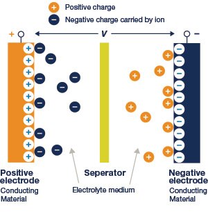
Figure 19: Cross-sectional View of an Electrochemical Double Layer Supercapacitor. Source: Electrochemical Supercapacitors for Energy Storage and Delivery, CRC Press
The structure of an electrochemical double-layer capacitor is very similar to that of an electrochemical cell; however, unlike the cell, there is no electron transfer across the electrode-electrolyte interface. As voltage is applied to the supercapacitor, ions in the electrolyte solution diffuse into the electrode pores of the opposite charge. Charges electrostatically accumulate at the interface between the electrodes and the electrolyte, forming two charged double layers with a very small separation. The overall capacitance of the supercapacitor can be considered as two differential capacitances connected in series.
The primary difference between a battery and a supercapacitor in terms of charge storage is whether charges are transferred across the electrode-electrolyte interface. During charging and discharging, a double-layer supercapacitor does not transfer any charge across the interface. In a battery, charge transfer is central to its function, due to faradic redox reactions. Other important differences between a battery and supercapacitor are:
- Electrochemical double-layer supercapacitors have much higher power densities than batteries
- Power delivery in supercapacitors is much faster than batteries
- Charge/discharge times are much shorter than those of batteries
- The lifecycle of supercapacitors is much longer than those of batteries
 |
 |
| Radial Leaded – Vertical Mount | Radial Leaded – Horizontal Mount |
 |
 |
| Surface Mount- Flat Configuration | Radial Leaded – Stacked, Oval |
Figure 20: The Vishay 196 HVC ENYCAP Capacitors are polarized energy storage capacitors with high capacity and energy density for energy harvesting and power line backup applications.
8.2 Electrochemical Pseudocapacitors
Pseudocapacitors are an emerging type of supercapacitor that have higher energy density and capacitance, but lower power density and fewer life cycles than electrochemical double-layer supercapacitors. Pseudocapacitors store charges differently than electrochemical double-layer supercapacitors do. While the double-layer supercapacitor’s charges are physically accumulated on an electrode's surface, a pseudocapacitor’s charge storage comes from faradic charge transfer in the electrode layer via reduction-oxidation (redox) reactions, which are similar to the electrochemical reactions in rechargeable batteries.
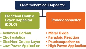
Figure 21: Comparison of Electrochemical Double-Layer and Pseudocapacitor.
The electrodes of pseudocapacitors are built with electrochemically active materials (metal oxide or conductive polymer), which facilitate the electrochemical redox reactions. Electrolyte ions diffuse into the electrode's pores, causing quick yet reversible surface redox reactions.
Pseudocapacitance in conjunction with electrochemical double-layer capacitance both contribute to the total capacitance of the device. The amount of pseudocapacitance depends on the surface area, material, and structure of the electrodes. Because both charge accumulation and charge transfer from redox reactions function to store charges, the capacitance of pseudocapacitors is much greater.
8.3 Supercapacitor Charging
Unlike batteries, supercapacitors can be charged or discharged countless times. They can also absorb energy quickly without much effect. But like batteries, self-discharge, ambient temperature fluctuations, overvoltage, and degradation of the electrolyte over time all affect supercapacitor life expectancy. Supercapacitors face many of the same challenges as batteries in terms of charging as well, although there are fewer parts characterized for this use. Dialog Semiconductor recently released a reference design for supercapacitor charging. To learn more, please visit ESSENTIALS Power II.
 |
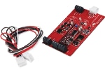 |
| bq33100 Super Capacitor Manager - TSSOP (24) | bq33100 Super Capacitor Manager EVM |
Figure 22: The Texas Instruments bq33100 Super Capacitor Manager is a single-chip solution for charge control, monitoring, and protection for 2, 3, 4, or 5 series Supercapacitors with individual capacitor monitoring and balancing, or up to 9 series capacitors with only the stack voltage being measured.
8.4 Supercapacitor Cell Balancing
Supercapacitors are rarely used as single cells. More often than not, they are designed in banks and usually connected in a series configuration. As such, each cell may be slightly different in terms of capacitance, internal resistance and/or leakage current. As a result, cell voltage imbalances can occur. To correct an imbalance, passive balancing can be employed using balancing resistors. The other approach is to use an active voltage balancing circuit.
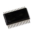
Figure 23: Example of a Supercapacitor (EDLC) Cell Balancer IC
The BD14000EFV-CE2 is an LSI IC designed as a self-controlled cell balancer It has a built-in shunt-type power storage element balancer function that can respond to 4 to 6 cells All the functions necessary in a cell balancer are built-in This chip can be used for electric double layer capacitors(EDLC with cell detection voltage range of 2.4V to 3.1V It has a built-in multiple over-voltage detection function and can also detect abnormal modes such as any deterioration in cells
8.5 Supercapacitor-Battery Energy Storage
Supercapacitors can be coupled with another energy storage device to create a hybrid energy storage system. Batteries and supercapacitors possess the right characteristics for using them in hybrid storage applications. A battery's high energy density and a supercapacitor’s high power density provide a storage system that’s more effective than each one by itself.
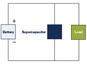
Figure 24: Direct Coupling of a Supercapacitor and a Battery
The direct coupling of a supercapacitor and a battery in parallel is shown in Figure 24. The advantages provided by this arrangement relative to a battery-only system include a capability to elevate peak power, greater efficiency, and extended battery life. But there are some limitations as well. The load and supercapacitor voltages float based on the battery voltage, which is affected by its state of charge, and therefore limits the full use of the power of the supercapacitor. The terminal voltage of the system follows that of the changing battery voltage and isn’t regulated. Due to these limitations, indirect coupling featuring controller circuits improve the system performance.

Figure 25: Indirect Coupling of a Supercapacitor and a Battery
Adding a DC-DC converter to the system (Figure 25) provides the voltage regulation that a direct system does not possess. Other advantages include:
- Electrochemical double-layer supercapacitors have much higher power densities than batteries
- The supercapacitor and battery voltages can now differ from one another, providing design flexibility
- A constant terminal voltage can be maintained by the whole system
- No need for an external charger since the DC/DC converter is part of the system
9. Energy Storage in Energy Harvesting Applications
As an alternative to using batteries and line-powered battery chargers to power electronic devices, it is often more convenient to utilize ambient energy, such as wind, solar, mechanical vibration, or temperature differences, by harvesting the energy to power these devices.
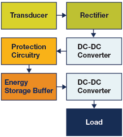
Figure 26: Block diagram of an energy harvesting power system with energy storage buffer
Energy harvesting systems usually include a storage device (e.g., capacitor or supercapacitor) to store the energy for future use as determined by energy harvesting power management ICs. These ICs serve several functions, including (a) capturing the energy from the transducer, (b) converting the converted energy to the appropriate regulation voltages, and (c) charging energy storage devices (i.e, batteries and/or supercapacitors).
Perhaps the most common type of energy harvesting application is solar power. When charging a battery from a photovoltaic source, certain chargers have been optimized to get the maximum power transfer from transducer to battery. This is called maximum power-point tracking (MPPT). Read more about energy harvesting technology in the element14 Power Essentials II learning module. See Power Essentials II
10. Glossary
- C Rate: a measure of the rate at which a battery is discharged relative to its maximum capacity. A 1C rate means that the discharge current will discharge the entire battery in 1 hour.
- Cell: the smallest energy unit of a battery module of a battery pack.
- Coulomb’s Force: the strength of the electrostatic force between two charged bodies as defined by Coulomb's Law.
- Depth of Charge: the percentage of battery capacity that has been discharged and expressed as a percentage of maximum capacity.
- Energy Density: the amount of energy stored per unit volume in watt-hours per cubic liter (Wh/l).
- Faradic Reaction: a charge transfer reaction at an electrode/electrolyte interface.
- Module: two or more battery cells connected in either series or parallel.
- Nominal Voltage: the rated or named voltage of a battery.
- Non-faradic reaction: a reaction that does not involve a charge transfer at the electrode / electrolyte interface.
- Open-Circuit Voltage: the voltage between the battery terminals with no load applied.
- Pack: two or more battery modules connected in either series or parallel.
- Passivation (layer): growth of an oxide layer of shield material, created by a chemical reaction or from oxidation in the air.
- Power Density: the maximum available power per unit volume in watts per cubic meter (W/m3).
- Pseudocapacitance: a type of capacitance which occurs at the surface of some types of electrodes, created by faradaic electron transfer across the electrode-electrolyte interface.
- Specific Energy: the nominal battery energy per unit mass in Watt-hours per kg (Wh/kg).
- Specific Power: the maximum available power in a battery per unit mass in Watts per kilogram (W/kg).
- State of Charge (SOC): the current battery capacity as a percentage of maximum capacity.
- Terminal Voltage: the voltage between the battery terminals with load applied.
*Trademark. Avnet is a trademark of Avnet Inc. Other logos, product and/or company names may be trademarks of their respective owners.
Shop our wide range of energy storage products, including batteries, capacitors, battery management, charger, and protection ICs, and associated development boards.
Test Your Knowledge
Power Skills 3
Are you ready to demonstrate your Power Essentials Energy Storage Electronics knowledge? Then take a quick 15 question multiple choice quiz to see how much you've learned from this Essentials of Power 3 Module.
To earn the Power Essentials 3 Badge, read through the module to learn all about Energy Storage Electronics, attain 100% in the quiz, and leave a comment.


Top Comments