


Hacking the HATs
1) Intro
Got the challenger kit in the mail: RPi4 2GB, Enviro HAT (PIM486), Automation HAT mini (PIM487), Pico HAT Hacker (PIM300)
Raspberry Pi 4 2GB
Installed "Raspberry Pi OS" on an empty SD card
Luckily I had a micro HDMI adapter to connect the monitor
Hooked up USB keyboard and touchpad
2A USB-C cell phone charger (will be getting the recommended 3A power source).
Comparing it to RPi Zero I have worked with before it booted up lighting fast, and using it is a breeze.
Next up was testing of the HATs
Enviro (PIM486)
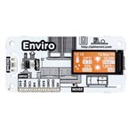
Followed instructions from https://github.com/pimoroni/enviroplus-python (same repository is for "Enviro+" and "Enviro", we got the Enviro)
On our board we have:
- ST7735 - 0.96" colour LCD (160x80) (SPI)
- BME280 - temperature, pressure, humidity sensor (I2C)
- LTR-559 - light and proximity sensor (I2C)
- MEMS microphone (I2S/PCM)
Main difference is that Enviro does not have these sensors included in Enviro+:
- Breakout for PM sensor (PMS5003 particulate matter sensor)
- MICS6814 -Gas sensor
- ADS1015 - Analog to Digital Converter (used to read Analog values from Gas sensor)
At first it did not worked great, temperature and humidity values where way off and very variable.
I found out it was like that because of the HAT placement and RPi radiating heat over Temperature sensor, and temperature is used for adjusting humidity reading.
In examples there is cpu temp compensation code, but from my experience it was not reliable enough.
The solution was to get the HAT away from the RPi (using wires or ribbon cable) and remove the cpu temp compensation code. Now its working great.
weather-and-light.py example is my favorite and will probably reuse most of its code for my project (without cpu temp compensation).
Automation HAT mini (PIM487)

Followed instructions from https://github.com/pimoroni/automation-hat (same repository is for "Automation HAT", "Automation pHat" and our "Automation HAT mini")
CURL command did everything except the copy of examples, so I did that manually (downloaded the gitHub repository zip)
On our board we have:
- ST7735 - 0.96" colour LCD (160x80) (SPI)
- ADS1015 - Analog to Digital Converter (used to control analog channels) (I2C)
- 3 Analog (ADC) channels - range inputs that measure supplied voltage from 0-24V (test: wire +5V to any of the ADC channels)
- 3 Inputs - dual state input: low (<1V) and high (>3V) (test: wire +5 to any of the 3 Inputs
- 3 Outputs - up to 24V sinking output (sinking means you connect +5/12/24 to load and from load to Output screw terminal as Ground)
- 1 Relay - mechanical switch (max25V2A, can be used as normally open or normally closed (test: make an electrical circuit and loop it through the relay)
Github provide 3 separate examples with nice display graphics:
- analog.py - analog range inputs
- input.py - digital inputs
- output.py - digital outputs
- no relay example - can be utilized using: automationhat.relay.one.toggle()/on()/off()/is_on()/is_off()/write(boolean)
Pico HAT Hacker (PIM300)
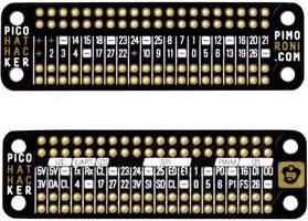
Nothing special about this board at the first glance other than pin naming, and can do few things with it
- solder two rpi headers (female/male) and use it for offsetting some other HAT
- solder other side directly on the rpi header leaving enough space to put another hat on it so you can end up with two hats (if you can fit them)
- use as a hat and on the place off the second header solder in wires that go to the rest of your boards
2) Problem
When I found out that two HATs that we got in the challenger kit did not stack I was quite disappointed. Mostly because RPi4 2GB has more than enough computing power (and pins) for much more sensors and controls than those two HATs.
If we go to https://pinout.xyz/phatstack and select Automation Hat Mini and Enviro Plus (there is no option for basic Enviro HAT), we can see the clashing pins

From what we can see here there are 6 pins clashing so there should be no way to use them on single RPi.
But I can't accept it 
automationhat.relay.one
3) Research
If you are not in interested in details just skip to chapter 4) Solution
RPI Interfaces
To solve the problem we need to understand few different interfaces that you can use on RPi.
The one that we are interested in are:
- I2C
- SPI
- I2S/PWM
I2C - Inter Integrated Circuit
This is a two-wire communication interface, on these two wires you can connect multiple devices, and each of them has an unique address (usually set by the manufacturer).
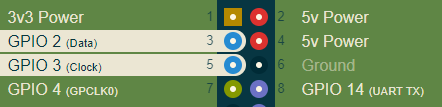
These two pins are used for I2C on RPI (source: https://pinout.xyz/pinout/i2c)
- GPIO 2 (data)
- GPIO 3 (clock)
We have multiple I2C devices on our HATs:
- Enviro > BME280 (address - 0x76 or 0x77)
- Enviro > LTR-559 (address - 0x23)
- Automation mini > ADS1015 (address - 0x48)
So all of these devices have different addresses and are safe to connect all together (both use GPIO 2 and 3)
SPI - Serial Peripheral Interface
This is a 4 wire serial bus used to connect multiple devices, 3 wires are common and 1 wire (CS-Chip Select) is separate for each device.
On RPi there are 2 SPI busses:
- SPI0: GPIO 7, 8 as CS pins and 9, 10, 11 as common pins
- SPI1: GPIO 16, 17, 18 as CS pins and 19, 20, 21 as common pins
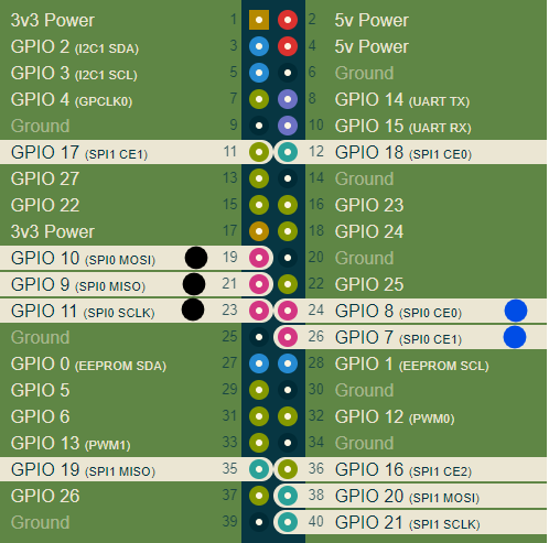
Our two HATs use SPI0 bus for ST7735 LCD display. They use common GPIO 9, 10,11 (marked black) and these are safe to share between both displays
But they also both use same CS pin GPIO 7, and we have two CS pins available on SPI0 (GPIO 7 and 8) so one of them should be switched to GPIO 8.
I2S/PCM - Pulse-code Modulation
Used for digital audio input or output, uses 4 GPIO pins
- GPIO 18 - Serial Clock
- GPIO 19 - Word select
- GPIO 20 - Serial Data In
- GPIO 21 - Serial Data Out
Enviro HAT uses pins GPIO 18, 19, 20 (marked with blue dot) for MEMS microphone
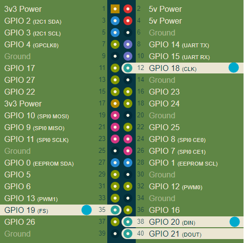
Enviro
This is the pinout of Enviro Hat:

Pins marked with red dot are not connected on Enviro, and are only used on Enviro+ so we don't have to take them into consideration
- ST7735 (display) - GPIO 7, 8, 9, 10, 11, 12
- BME280 - I2C: GPIO 2, 3
- LTR-559 - I2C: GPIO 2, 3
- MEMS microphone - I2S: GPIO 18, 19, 20
Automation HAT Mini
This is the pinout of Automation HAT Mini:
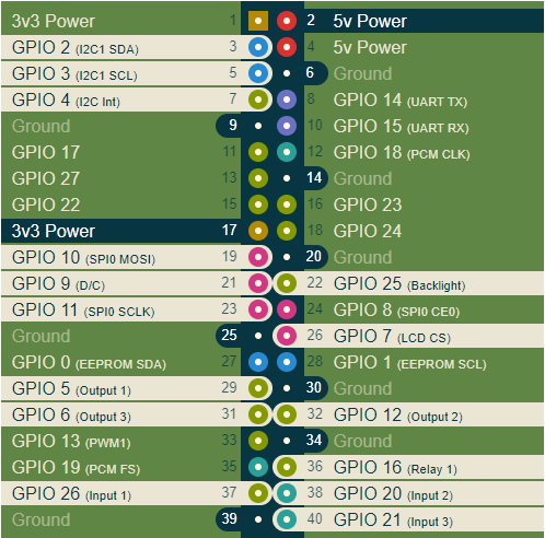
Thing to note here is that this HAT takes the 3V3 Power from pin 17
- ST7735 (display) - GPIO 7, 8, 9, 10, 11, 25
- ADS1015 (Analog channels)- I2C: GPIO 2, 3, 4 (not sure what is GPIO 4 about, still trying to get answers)
- 3 Inputs - GPIO 26, 20, 21
- 3 Outputs - GPIO 5, 12, 3
- 1 Relay - GPIO 16
Clashing pins
As a result of research these are the only clashing pins:
| GPIO | Enviro | Automation HAT Mini |
|---|---|---|
| 7 | SPI CS | SPI CS |
| 12 | Display Backlight | Output 2 |
| 20 | I2S Serial Data In (microphone) | Input 2 |
4) Solution
I would like to keep the Automation HAT Mini unchanged so official automationhat library can be used, so only changes are going to be made to enviro pinout
Enviro GPIO 7
This is one of a SPI0 bus CS pins (we have two available), so we will move it on Enviro to other available CS pin GPIO 8. On Automation HAT Mini it will stay the same.
Important thing here is to change that pin in the Enviro example code (ST7735 initalization).
Enviro GPIO 12
This one is used on Automation HAT mini as an Output 2 pin, and on the Enviro for display backlight.
On Enviro I will switch that pin to GPIO 25, it's the same pin Automation HAT Mini is using for backlight (it can be shared)
I am going to use both displays together, so if you want to change backlight individually I suggest you put it on some other empty pin (eg pin GPIO 13)
Also don't forget to change backlight pin in the example code (ST7735 initalization).
ST7735 Initialization
Sample code for display initialization with modified Enviro HAT pins
#Enviro LCD
dispEnviro = ST7735.ST7735(
     port = 0,
     cs = 0, #GPIO 8
     dc = 9,
     backlight=25,
     rotation=270,
     spi_speed_hz=10000000
)
#Automation HAT Mini LCD
dispAutomation = ST7735.ST7735(
     port = 0,
     cs = 1, #GPIO 7
     dc = 9,
     backlight=25,
     rotation=270,
     spi_speed_hz=10000000
)
Enviro GPIO 20
This one is used on Automation HAT mini as an Input 2 pin, and on the Enviro for microphone data.
As I don't see any use for a microphone in my project I will disconnect all microphone pins on Enviro: GPIO 18, 19, 20
If you need the microphone you would need to move the Output 2 on Automation HAT to some other empty pin.
Rewiring of any Automation HAT Mini outputs or inputs will require the change in the official automationhat library (not recommended) or using the HAT without official library so you can define the pins by yourself.
Proof of concept
Here is a video of the working example. It's not pretty but it works 
5) Auto-Enviro HAT
So this new "Auto Enviro HAT" will be the combination of Enviro, Automation HAT Mini and Pico HAT Hacker.
Requirement is to be able to quickly connect/disconnect modules for replacement or inspection.
Idea is to use Pico HAT Hacker with one 40pin female header to plug into RPi, and two other 40 pin male headers, one connected to Enviro and the second to Automation HAT Mini.
male headers would be connected with wires to Pico HAT Hacker so they can be positioned away from RPi heat (messes with temperature readings)

Wiring schematics
I will upload pictures of finished Auto-Enviro HAT once I put it all together.
6) Conclusion
For me this was an educational journey about RPi pins and communication protocols.
Learned a lot by reverse engineering these two hats and trying to put them together.
Took some time to do so I hope it will help someone else to learn and implement.
Top Comments