


Introduction
Hi! This will be my second update on the project BEEP. In the last blog I covered the idea and plan behind the whole project, and for this one I'll cover the first one of the modules, the ultrasonic module. As the name suggests this module uses an ultrasonic distance sensor (HC-SR04). When I think of a sensor this is the one that first comes to mind. It is really simple to use and yet works really good with sensors based on that technology all around the place. My idea is to create a plug n play module with this sensor which will showcase the possibilities of this sensor, and then give the user the opportunity to re-program the module themselves. In this blog I'll show my thought process behind this module, how I made it and programmed it. To get to the last model with which I am satisfied I went through few different designs with me wanting to add new features to it and adjusting the design.
Design
I'll start with the enclosure. The first maker space opened in my country two months ago so I finally have the ability to use a 3D printer for projects. Naturally my first idea was designing a small boxy enclosure which would contain the sensor and an Arduino Nano and few others things. I stuck with that idea for quite a while until one day I had to change a dead light bulb in my house, when one thing led to another and I finished with this idea:
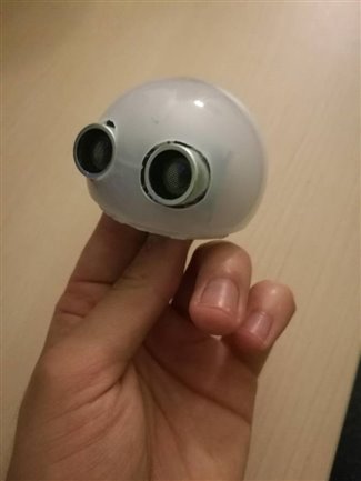
 This was the first step to me designing this module, the other part of the enclosure is the 3D printed under part but I'll get that to end because its design had to change through different versions. Before I start with different versions I'll list the parts and their function which are in all of the versions.
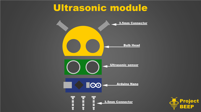
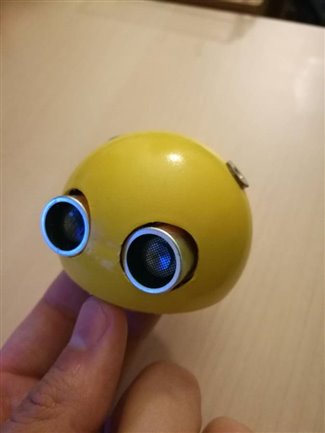
This design is purely conceptual and here to show the flow of my thoughts and I didn't even make it, I started with the second version (V1.1) which can be seen on the next image:
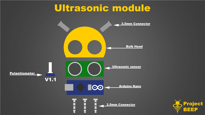
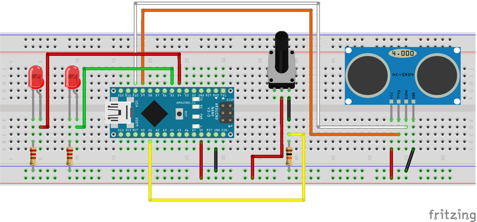
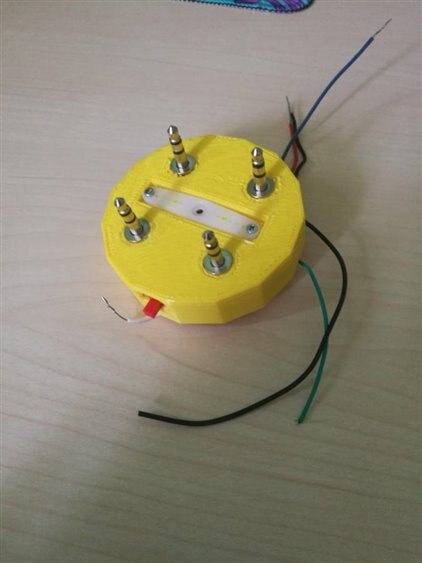
The addition I made was a potentiometer, here is the full explanation of how this version of the module worked. The female 3.5mm connectors are used as ports for plugging in LED antennas which can be used as indicators, I like the modular design this way rather than making them as part of the Bulb Head because some projects may require removing the antennas, and also adds a lot of customizability to the looks of the module, here is a video of me making an antenna:
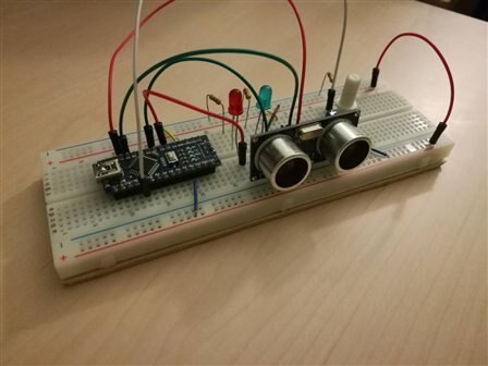
The LEDs are cool looking feature in my opinion but they are also pretty useful to be used as indicators. The one thing I would like to do with this is to use RGB LEDs instead of standard LEDs, which can be done with different 3.5mm connectors. The way I made this is using a solid brass wire as the spine of the antenna and heat shrink tubing as skin of the antenna. This was a purely a switch type sensor so it sent either value 0 if it's not activated or 1 if it's activated. Now, the potentiometer is used with the LEDs to set the activation distance, this is done by putting an object at the desired distance and adjusting the potentiometer so that the LEDs turn on/off at that distance. I feel this is a quite intuitive way of using this sensor, but can also be used like this for variety of projects, here is the schematic of the module and the video of setting the desired distance and testing the module:
And for the end of this version here is the code I used for it:
const int trigPin = 9;
const int echoPin = 10;
const int greenLed = 5;
const int redLed = 3;


float duration, distance;
int pot, critical;


void setup() {
  pinMode(A1, INPUT);
  pinMode(greenLed,OUTPUT);
  pinMode(redLed,OUTPUT);
  pinMode(trigPin, OUTPUT);
  pinMode(echoPin, INPUT);
  Serial.begin(9600);
}


void loop() {
  digitalWrite(trigPin, LOW);
  delayMicroseconds(2);
  digitalWrite(trigPin, HIGH);
  delayMicroseconds(10);
  digitalWrite(trigPin, LOW);


  duration = pulseIn(echoPin, HIGH);
  distance = (duration*.0343)/2;
  Serial.print("Distance: ");
  Serial.println(distance);


  Serial.print("Critical value is ");
  pot = analogRead(A1)-500;


  if(pot<0) pot = 0;
  if(pot>500) pot = 500;
  critical = pot*0.2;
  Serial.println(critical);


  if(distance<=100)
  {
    if(critical>=distance)
    {

      digitalWrite(greenLed,HIGH);
      digitalWrite(redLed,HIGH);
      delay(100);
      }
      else
      {
        digitalWrite(greenLed,LOW);
        digitalWrite(redLed,LOW);
        delay(100);
        }

    }
    else
    {
      digitalWrite(greenLed,LOW);
      digitalWrite(redLed,LOW);
      }

  delay(100);
}
For the V1.1, I set the maximum measuring distance to 1m just to keep it safe, and made it so it has 500 points of desired distance adjustment, which means you can get accuracy of 2mm, if you are precise enough with the potentiometer that is.While testing I found that you can get accurate to within a centimeter no problem, and for this version I think that's plenty. This was the base idea for this module but I just felt it lacked a lot, and while it did great simplifying the sensor I feel it also looses a lot, so here are the two steps I went through to get to what I call the last version of the module (V1.3):
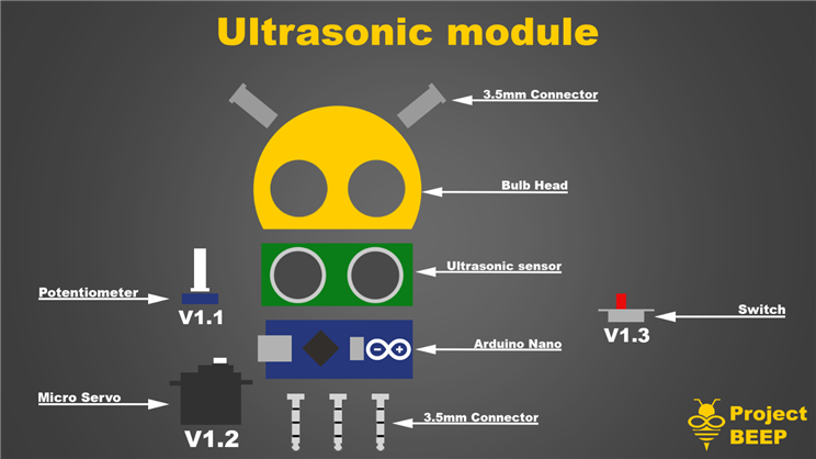
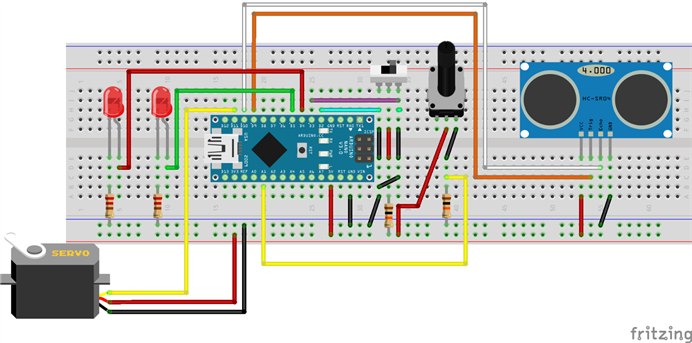
The first addition is the micro servo, though for now it doesn't really have any function but it will in the future, and the addition of a small switch which will switch between two different modes. The first mode being the already described switch mode, which would be the simple use of this module, and the other setting be a smart I2C module which would send the distance to the main body module. Since I am already going with I2C here this is where the micro servo can add a lot of features to the module, but again I won't be doing anything with it yet, I'll be saving that part for the pre-loaded programs part which I talked about in the first blog. Now on the other side as mentioned before, I am using a Raspberry Pi, running a Raspbian. Now comes the part where I need to put this into a compact package. The light bulb will contain the 3.5 mm female connectors, ultrasonic sensor and the Arduino, which means we still need to add the servo, potentiometer, switch and 3.5 mm male connectors. As I have already mentioned a maker space opened up so I got the chance to do my first ever 3D prints. In all honesty they didn't work out 100% as I wanted, I made the tolerances to small now knowing what I am going into, but in the end, I made it work. Firstly let's start with the drawings for the brackets that will hold the rest of the stuff:
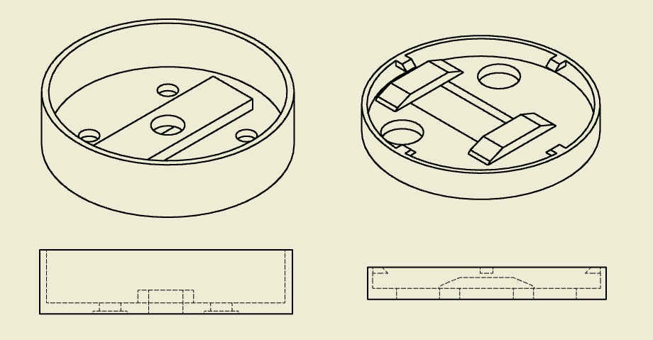
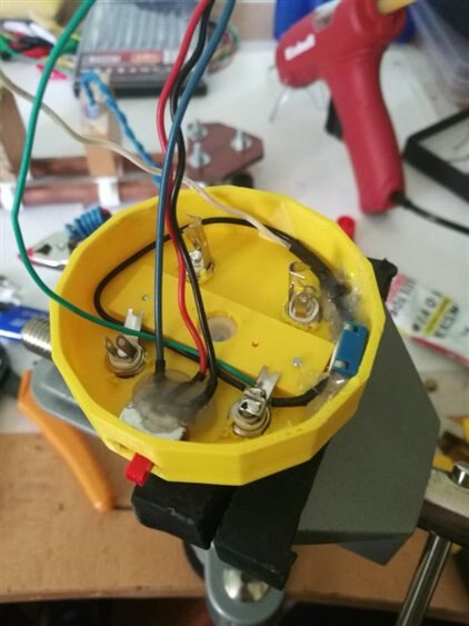
The bracket on the right is designed to hold the micro servo, and have openings for wires to go through (also had little pieces of plastic which were supposed to grab the light bulb, but didn't work so in the end I used hot glue to put it together), the bracket on the left is designed to hold the mount for the micro servo, as well as the 3.5 mm connectors, potentiometer and a switch. The general idea was for one to fit inside the other and rotate like that, but due to my bad calculations that didn't work out so in the end they spin on top of one another, but still looks pretty good. Now after printing these things comes the very fun part, assembly. It required a lot of soldering and cable management for all of it to fit inside and work, but in the end i am thrilled to say that it did! Here are some pictures of the assembly:
| {gallery} Assembly |
|---|
|
|
|
|
|
|
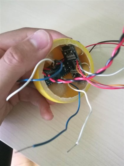
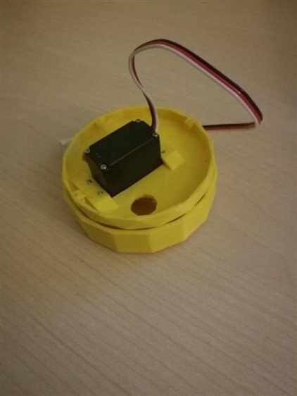
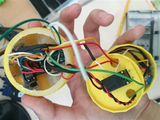
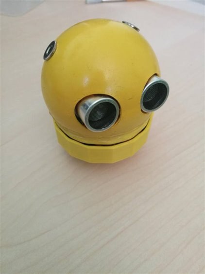
While it was very fiddly to put together, it was pretty fun, and of course rewarding in the end when all of the connections worked, now for the module to be completed it needs 2 more things and those are the antennas and the knob for the potentiometer, also one thing worth mentioning is that I made a small hole in the back of the light bulb so that the Arduino port can be accessed without taking the whole thing apart and putting it back together which would be a nightmare, this will give a lot of flexibility to the user. As for the potentiometer I mounted it inside right next to the wall and drilled a tiny hole so it can be used with a small hex or the knob it came with. Here is the picture of all of the parts of the module:
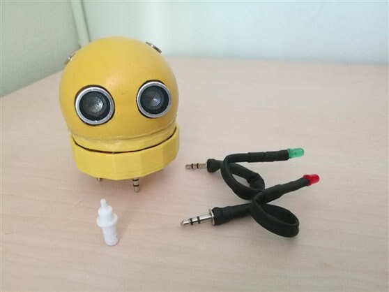
Now all that's left is testing is explaining the ports and testing it all out, the bottom of the module has 4 3.5 mm connectors, in other words 12 ports in total. I didn't have to use all of them, but tried utilizing as many as I can. Firstly the Arduino and the whole module with that can powered through the pins which are connected to the Ground and Vin pin on the Arduino, one of the pins is the output for the switch type operation module, and two more ports are reserved for I2C communication, which are connected to the SDA, and SCL pins on the Arduino. One of the ports has the 5V from the Arduino, I did this primarily for cable management but can also be used as a voltage regulator for some smaller things like LEDs, and in the end I connected two of the ports so I can later on use that to test if a module is connected or not, by having the same pins connected on every head module. In the end I would like to show the working module through 2 videos, on showing a slight movement of the head running a simple servo control code, as well as showing the code shown above working on the finished module:
While some of things didn't work out as I have planned out, some things worked much better, but in the end I am extremely happy with how it turned out. The design of this module will greatly influence the designs of upcoming modules, and the project itself. There's a lot of cool things I like about this part of the project, specially the part where I finally got the use a 3D printer! It really makes everything different, where now I can go and design a 3D model and after a few hours there it is. The next thing for me with this project will be exploring the bluetooth capabilities of the Raspberry. The plan is connecting them via bluetooth and sending information about the joysticks and buttons pushed. It's a pretty slow start but I am happy with how it went. Thanks for reading through, really hope you liked the blog!
Milos
Top Comments
-

genebren
-
Cancel
-
Vote Up
+1
Vote Down
-
-
Sign in to reply
-
More
-
Cancel
Comment-

genebren
-
Cancel
-
Vote Up
+1
Vote Down
-
-
Sign in to reply
-
More
-
Cancel
Children