For all the parts to this project, click here! Smart Doorbell System
Introduction
The Smart Doorbell System is an idea for a wireless bell-push/chime system with better range and features than expected from existing systems!
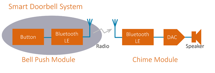
This blog post concentrates on the entire left side of the diagram below; the bell push module.
If you’re interested to know more about the doorbell project then click the link above to all the earlier parts of the project, otherwise read on here, to see the design considerations for a low-cost but hopefully reliable outdoor remote button module that could have multiple uses beyond a doorbell system.
Circuit Design
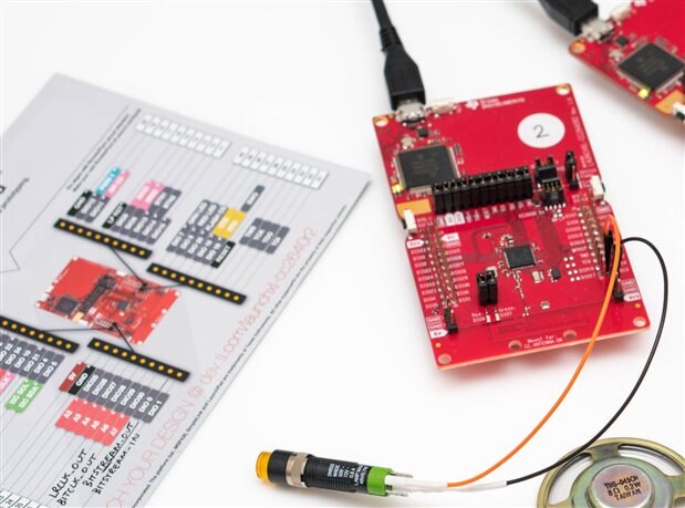
The heart of the design is based around the CC2640R2 chip from Texas Instruments. It is available on a dev-board called the CC2640R2 LaunchPadCC2640R2 LaunchPad. That is rather large for a bell push module, so the design has been re-implemented.
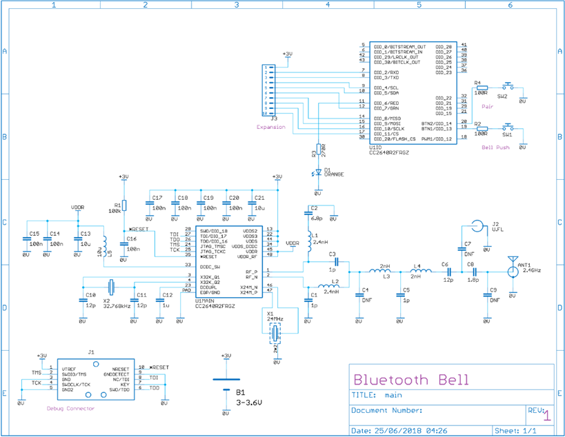
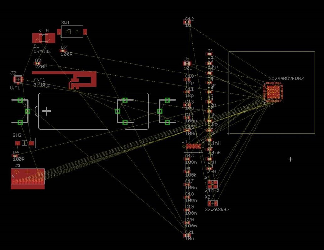
The design closely follows the existing LaunchPad design where possible but with some differences. Firstly the debugger portion and external Flash memory have been removed. This will provide some power savings and reduce the size too. Secondly owing to the possible locations where this device could be installed, some environmental and reliability considerations were needed. The components (this applies particularly the crystals) were chosen to allow operation in sub-freezing temperatures. Here is the circuit diagram (click to expand):
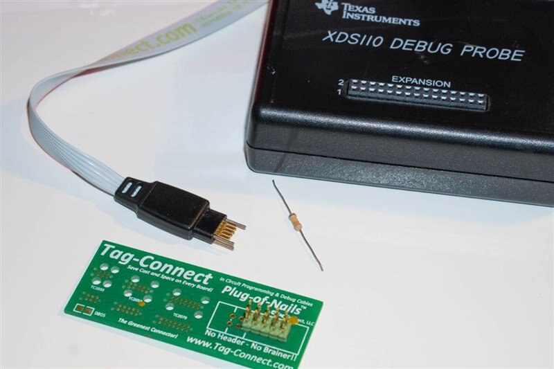
Since a very small circuit board is desired, there isn’t much space for a large debug connector. Instead, the Tag-Connect system is used, shown at the bottom-left of the circuit diagram. It uses a springy clip that is compact. Costs are also saved because it just requires the PCB to have some pads which are zero cost of course. The photo below shows the Tag-Connect clip next to a typical 1/4W resistor for size comparison. Texas Instrument's XDS110 debug probeXDS110 debug probe will be used for programming and debugging the CC2640R2.
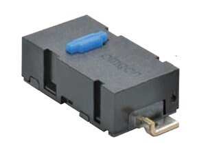
For the bell push, a microswitch is used. These types of switches have a very short travel with a reliable action. The reason I wanted to use a microswitch is that it provides flexibility to allow different physical implementations of the plastic piece that will be pressed by the user. Excessive force will not damage the circuit board when a lever system is employed with springy metal or plastic. An unusually slim surface mount Omron microswitchsurface mount Omron microswitch was found. It is just 3mm thick! It has a stated durability of 5 million operations.
An LED will be provided for user notification (it will also be handy during initial debugging). After lots of searching, a very low current (2mA) Vishay LEDVishay LED with exceptional high brightness was selected. It is designed for backlighting applications and automotive use.
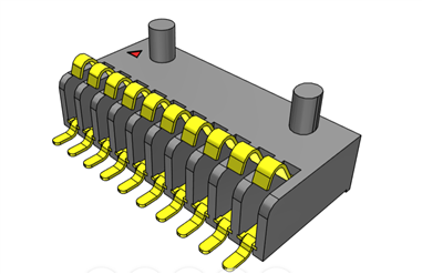
The PCB will have space for an expansion connector to press against it, so that future versions of this smart doorbell system could attach another PCB for expanded functionality (such as additional buttons, for a multi-resident apartment block). The expansion connectorexpansion connector consists of springy terminals that just press against pads on the bell push PCB. It therefore results in a zero-cost connector for this PCB.
The final battery has not been selected yet, I have a few candidates. The design will operate from a 3-3.6V battery or cell, and the design has pads for installing an AA-sized or 2/3 AA 3.6V cell if desired. The clips to hold it will be nickel plated for some corrosion resistance.
Antenna Design
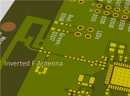
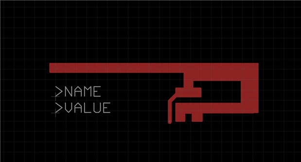
For the antenna, an omnidirectional design was preferred since it is not known where the chime module will be placed in relation to the bell push. The existing inverted F antenna design on the LaunchPad board is really good. There is lots of detailed information about it in TI's 2.4GHz Inverted F Antenna literature (PDF), which will save tens of thousands of dollars of effort compared to designing and obtaining test reports for custom antenna designs. Nevertheless, some work will be needed to match it since the ground plane will be different for the bell push compared to the LaunchPad design.
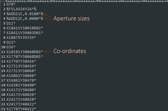
TI supplies the design in DXF and Gerber files. It was straightforward to directly input the TI design based on the Gerber file content. Most PCB CAD packages will likely have an import capability (often with limitations however!), but Gerber files are text based and easy to manually interpret.
Lines 3 and 4 specified the ‘aperture’ dimensions in ten-thousands of an inch, and then all the lines beginning with X were co-ordinates in ten-thousands of an inch. I directly typed each co-ordinate into EAGLE. With less than ten minutes of effort the final result was an identical replication of the TI antenna design. This was critical since even a fraction of a millimetre error would have affected the antenna’s capability. When mounted in the orientation shown, it should provide a doughnut shaped gain pattern with near omnidirectionality which is ideal for the requirements of this project. A connector will also be optionally installed for testing other antennas too.
Summary
A compact, general purpose BLE bell push or remote operated switch module has been designed. It also has some expansion capability for attaching additional hardware. For cost savings, two of the connectors (the debugger connector and the expansion connector) and the antenna are implemented using PCB pads and traces. For high reliability a microswitch is used.
Although it still needs to be measured, the device should operate for many years on a single cell.
The next step is to get the PCB designed and ordered. I’m looking forward to soldering it up and trying it out : )

Top Comments
-

genebren
-
Cancel
-
Vote Up
+2
Vote Down
-
-
Sign in to reply
-
More
-
Cancel
-

shabaz
in reply to genebren
-
Cancel
-
Vote Up
+2
Vote Down
-
-
Sign in to reply
-
More
-
Cancel
Comment-

shabaz
in reply to genebren
-
Cancel
-
Vote Up
+2
Vote Down
-
-
Sign in to reply
-
More
-
Cancel
Children