


After learning some basic function of the PSoC6, is time to implement them in my Smart Pet Home project.
I will start with controlling the water dispenser with PSoC6.
Unfortunately, my PSoC6 WiFi-BT Pioneer Kit was damaged because I accidentally short circuit it when dealing with a external power supply for my water pump. Therefore, my following blog post will be base on PSoC6 WiFi-BT Prototyping Kit.
BOM: PSoC6 WiFi-BT Prototyping Kit, a water pump, two 18650 battery, 18650 battery socket, 12 NPN transistor (C1815), a push button, a green LED, four 10k ohm potentiometers, some jumper wires, a bread board, a water pump and hose, a 1.5L water bottle, a 500ml water bottle, bendable steel wire, a plastic tray, hot glue gun and glue sticks.
Note: You can replace the four NPN transistor with a NMOS transistor. I use four NPN transistor just to mimic the function of a NMOS transistor because the NMOS transistor that I brought online is not delivered yet due to the Movement Control Order (MCO) in Malaysia.
Due to the Covid-19 that spread all around the world, most of the shop a closed during the period of the project, thus I'm using what I have got to build my project and some of the materials are not the best that suits its propose, you can always substitute the materials if you have access to a material that will perform better. For example, you can 3D-print the water dispenser if you wish to.
GitHub: https://github.com/wanfp97/PSoC6-Water-Dispenser
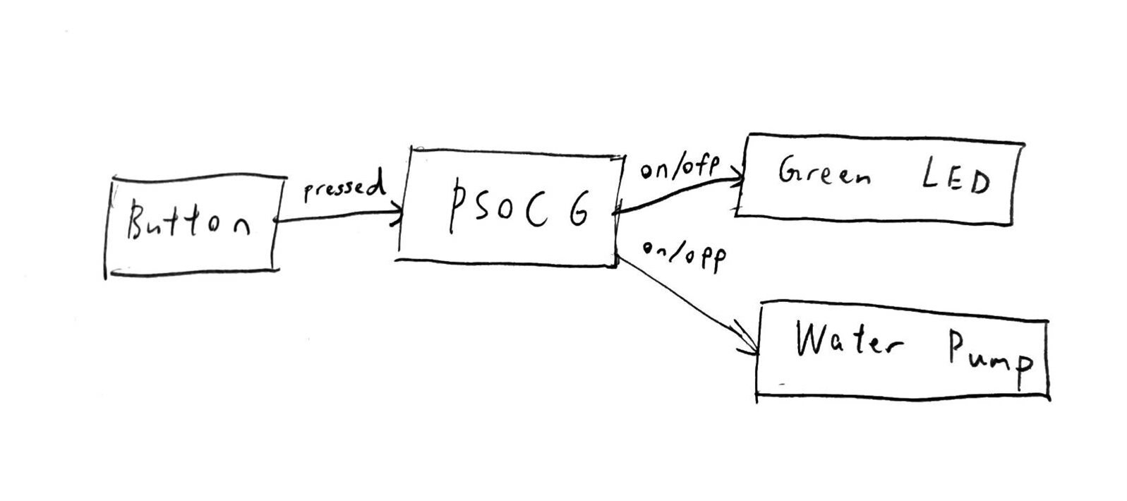
Block diagram:
Physical structure of water dispenser:
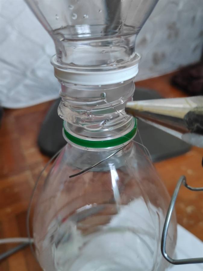
cut the top part of the 500ml water bottle and glue it on the top 1.5L water bottle to form a funnel shape for easier water input.
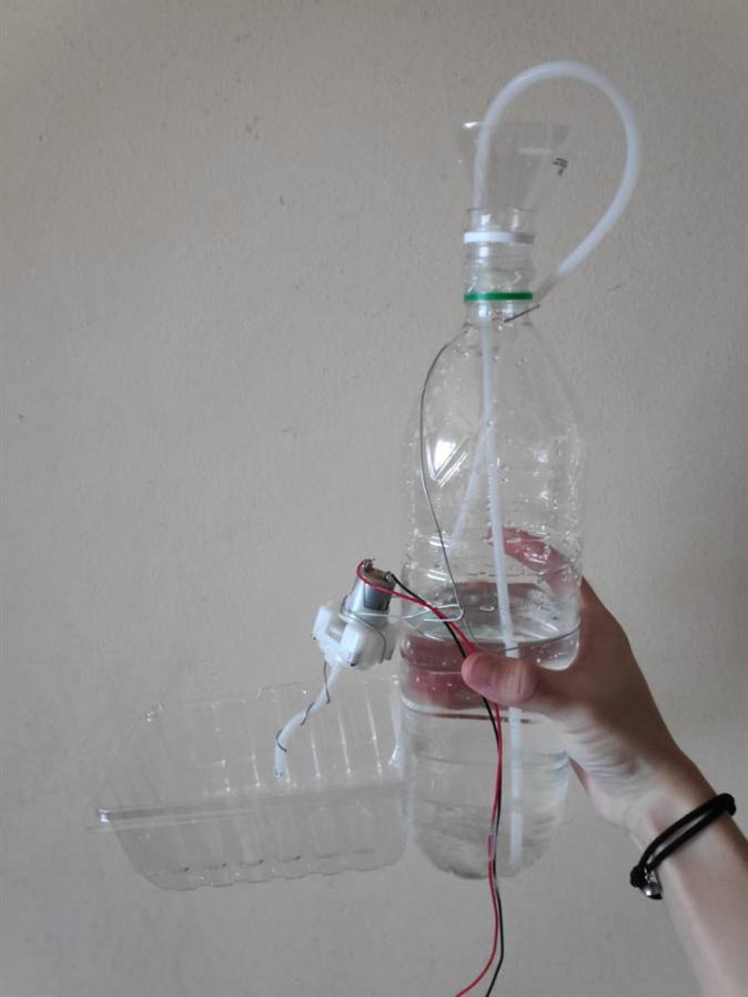
by using steel wire and hot glue gun, attach the water pump and hose, plastic tray, and water bottle as it shown in the picture above.
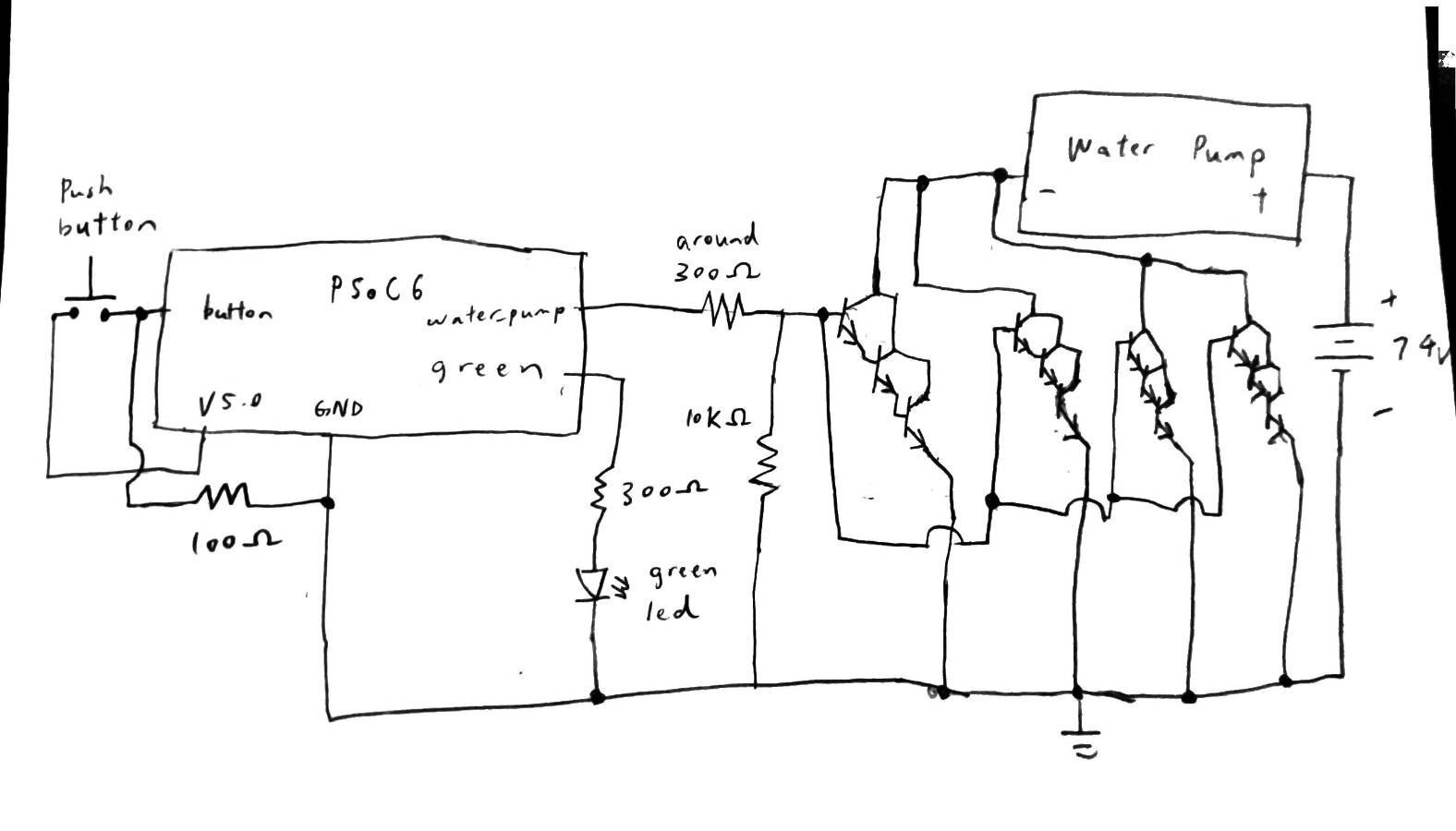
Schematic of water dispenser:
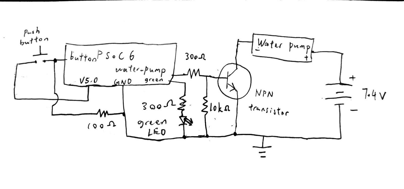
Initially, I have planned to connect the PSoC6, green LED, and water pump according to the schematic above. However, I have noticed that the current flowing through the water pump is too small to actually turn it on.
After checking the datasheet of my NPN transistor, I notice that the maximum rated current for the transistor is just 150mA and it is obviously not enough for the high current required to start the water pump.
The best solution would be just replace the NPN transistor with a NMOS transistor. However, due to the Covid-19, the NMOS transistor that I have purchased online is taking a longer time than usual to be delivered to me. As an alternative, I have decided to connect the NPN transistor parallelly to provide a higher current to pass through it. I have also cascaded the NPN transistors and to provide a greater amplification since the current supply from the PSoC6 is not sufficient to activate the water pump using only one stage on transistor.
After some trail and error, the picture below is my final version of my water dispenser schematic:
As always, I create a new Empty_PSoC6_Apps in ModusToolbox.
Using the basic interaction with ModusToolbox and Device Configurator that I have explained in my past blog post:
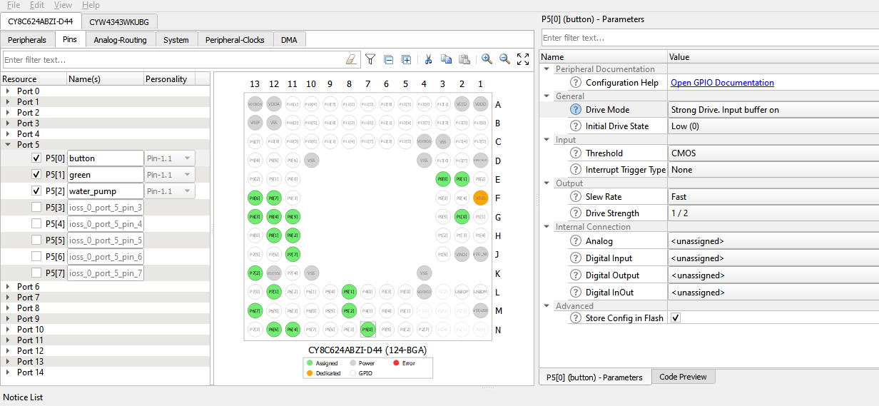
Configure pin for button, green LED and water pump.
I have selected Strong Drive. Input buffer on as the Drive Mode and Low(0) Initial Drive Stare for all of the pin. I will implement the pull-down resistor for the button pin at the hardware level in this case.
#include "cy_pdl.h" // include Peripheral Driver Library
#include "cyhal.h" // include Hardware Abstraction Layer library
#include "cycfg.h" // include device configurator library
/*******************************************************************************
* Function Prototypes
********************************************************************************/
static void button_intr_handler(void *handler_arg, cyhal_gpio_event_t event);
/*******************************************************************************
* Global Variables
********************************************************************************/
volatile bool button_intr_flag = false; // Boolean type variable to store the interrupt flag
int main(void)
{
    init_cycfg_all(); // configure pins as done in Device Configurator
    __enable_irq(); // enable interrupt
    cyhal_gpio_register_callback(button_HAL_PORT_PIN,
                                 button_intr_handler, NULL); // assigning isr handler for button
    cyhal_gpio_enable_event(button_HAL_PORT_PIN, CYHAL_GPIO_IRQ_RISE,
                                 1u, true); // interrupt on rising edge (button pressed)
    for (;;)
    {
     if (true == button_intr_flag) // if interrupt happens (button pressed)
     {
         button_intr_flag = false; // clear interrupt flag for further interrupt
         if(Cy_GPIO_ReadOut(water_pump_PORT, water_pump_NUM)==0UL)
         {
          Cy_GPIO_Write(green_PORT, green_NUM, 1UL); // green LED on
          Cy_GPIO_Write(water_pump_PORT, water_pump_NUM, 1UL); // on water pump
         }
         else
         {
          Cy_GPIO_Write(green_PORT, green_NUM, 0UL); // green LED off
          Cy_GPIO_Write(water_pump_PORT, water_pump_NUM, 0UL); // off water pump
         }
     }

    }
}
/*******************************************************************************
* Function Name: button_intr_handler
********************************************************************************
* Summary:
*   GPIO interrupt handler.
*
* Parameters:
*  void *handler_arg (unused)
*  cyhal_gpio_irq_event_t (unused)
*
*******************************************************************************/
static void button_intr_handler(void *handler_arg, cyhal_gpio_irq_event_t event)
{
    button_intr_flag = true;
}
///* [] END OF FILE */
writing the code in main.c. You can read through the comment beside the code or refer my previous blog post to understand the coding better.
Lastly, program and run it in the PSoC6, the result is as the video below:
In future blog post, I will try to improve the water dispenser, and probably, and a sensor to sense the water level and tell the water dispenser when to stop.