


Introduction
Hi! This will be my eighth blog for this challenge. In the last update (Fingerprint Skeleton Key - Key Picking Mechanism Part 1 - Design for a Cause Challenge - Blog Post #7) I've started and finished most of the build for the key picking mechanism. I will be finishing up that part of the build in the next update, but now I will go and get to know the last module that I will be putting onto the device, the vibration detection module. Besides the module I will also test out the battery, charging of the battery and monitoring battery levels. But first off, let's start with the vibration detection module.
Vibration Sensor Module
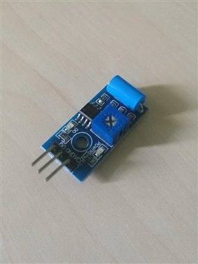
You might ask, why are a vibration sensor module? While it's not really necessary for this project, I thought it would be a good addition to the project. The way I plan on using the module is for fall detection. While this would require much more tinkering to work good, I thought it would be a good addition to the project. I will be using the SW-420 module. It comes with a potentiometer with which we can adjust how sensitive the module is. Let's connect it to a small test bench and try it out with an Arduino.
Test bench
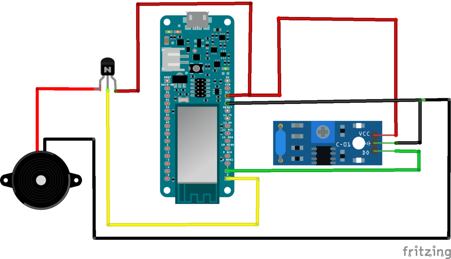
The connection to the Arduino is extremely simple, VCC --- 5V, GND --- GND, DO --- Pin 7. Besides the module I connected a buzzer to the circuit, because we will be activating the buzzer when the module is triggered. One more thing I connected in between is a small transistor since the pins on the Arduino aren't powerful enough for the buzzer. All that's left now is to code the Arduino.
Code
The basic code that is used for this module is to simply read the value of the Pin 7, and depending if its high or low we would know if the module was triggered. I started with that but encountered a problem. No matter what I did to the potentiometer on board the module was to sensitive for what I intended to use it for. As for what is designed it, it works great. So I was left with 2 options, changing the on board 10k potentiometer for something stronger, or trying to solve the problem by coding it differently. I pulled up the serial monitor and played a bit with the sensor and noticed a few things. When we have a stronger vibration (stronger hit/fall) we detect a few consecutive highs instead of only one. I put a delay of 50 between consecutive reads and tested it by well, throwing the module onto the table, and found that the threshold that I was looking for was around 5 signals. So in the end the code ended up looking like this.
void setup() {
  pinMode(6,INPUT);
  pinMode(7,OUTPUT);
  Serial.begin(9600);
}


int k=0;


void loop() {

    if(digitalRead(6)==HIGH)
  {
    k++;
    delay(50);
    while(digitalRead(6)==HIGH)
    {
      k++;
      delay(50);
      }
    }


  Serial.println(k);

  if(k>=5)
  {
    Serial.println("Module triggered");
    digitalWrite(7,HIGH);
    delay(150);
    digitalWrite(7,LOW);
    delay(50);
    digitalWrite(7,HIGH);
    delay(150);
    digitalWrite(7,LOW);
    delay(50);
    digitalWrite(7,HIGH);
    delay(150);
    digitalWrite(7,LOW);
    delay(50);
    digitalWrite(7,HIGH);
    delay(150);
    digitalWrite(7,LOW);
    delay(50);
    digitalWrite(7,HIGH);
    delay(150);
    digitalWrite(7,LOW);
    delay(500);
    }
    k=0;
    delay(100);
}
This code makes the module pretty hard to trigger, it really requires some kind of a drop or stronger hit. I would put a higher threshold for a real drop, but for testing purposes this works great. On the first prototype the whole system will be working a little bit differently. If the module was triggered, the buzzer would go on and off for 30 seconds for example. or until the user mutes it by pressing a button. Here is a video of me testing out the module with this code.
Test
Battery
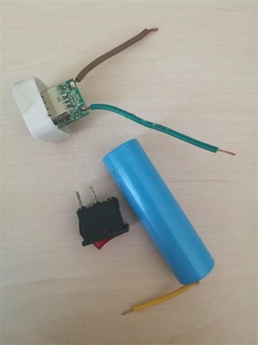
Since this is supposed to be a handheld device we need to have some sort of a battery on board. The Arduino MKR1000 has a connector for 3.7 V LiPo battery, but all of the one near me were pretty expensive, or had too long shipping time. So I decided with what I had, an old dismantled power bank. The great thing about this approach is that the power bank has an integrated voltage regulation circuit, as well as a charging circuit. This is all straight forward, to make it a bit more useful I added a switch and a small board for measuring voltage, which is essentially a voltage divider.
Build
| {gallery} Battery |
|---|
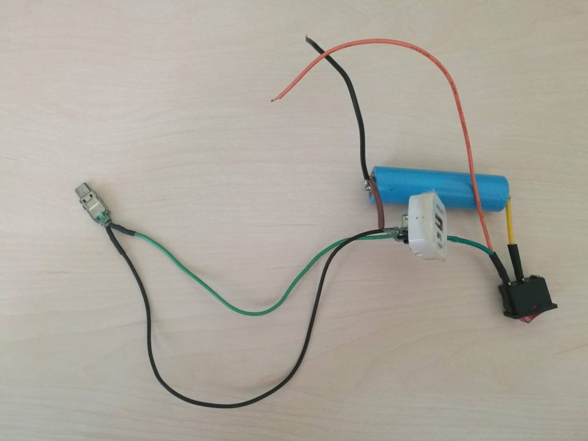
Parts: The parts I will be connecting together |
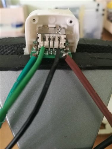
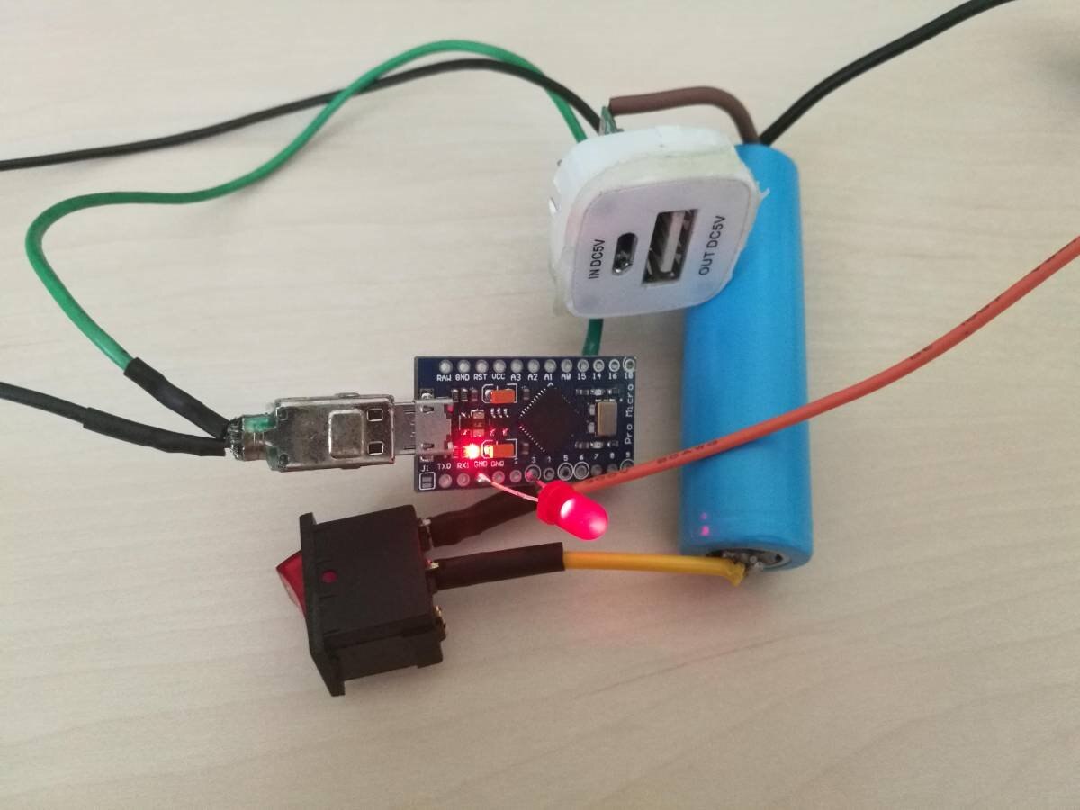
Output wires: I soldered the output wires of the voltage regulator on the back of the USB connector, the access is better there plus the whole device can be used as an ordinary power bank for charging other electronics. |
Micro USB: For connecting to the Arduino I went with a micro USB. I was reading around and read that to power through the Vin pin I would need at least 6.2 V, so I just stuck with the micro USB port. |
First test: To test out if everything worked correctly I connected it to a Pro Micro which also has the micro USB and everything worked great. |
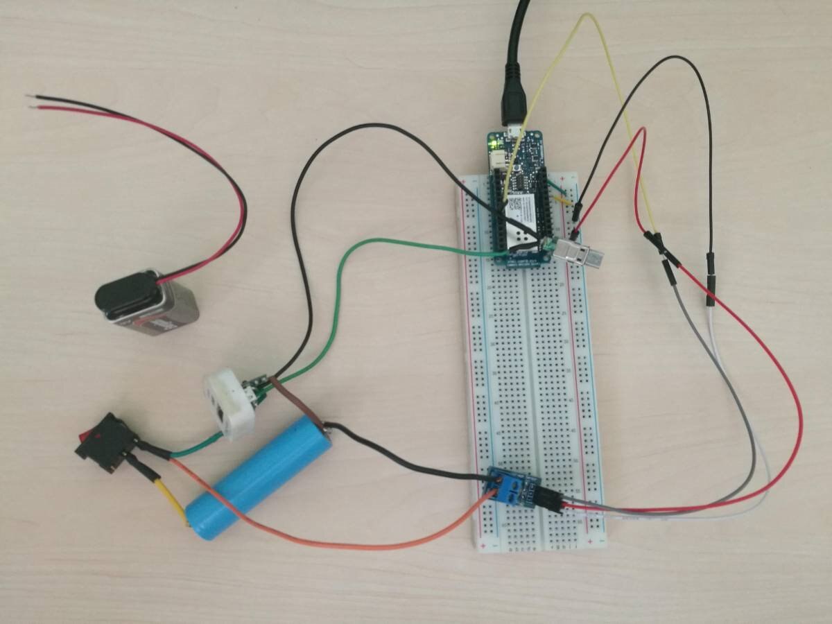
Test bench: And the last thing left to do is calibrate the voltage measuring circuit |
Measuring Voltage
Now we come to the last step for this part, measuring voltage. For that, as I've said, I'm using a voltage divider.
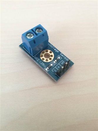
Connections to the Arduino are really simple, we connect the battery to the screw terminal, + and - to 5V and GND, and the S+ Pin to A6 or any other analog pin on the Arduino. The voltage from the voltage regulator was really stable, while the battery voltage had variations in the neighborhood of around +/- 0.04 V. So to calibrate the system as best as I can I used a standard 9 V battery (which had a voltage of 11 V) to calibrate everything. In the end here is the code and comparison between Arduino measuring and a voltmeter.
Code
void setup() {
  pinMode(A6,INPUT);
  Serial.begin(9600);
}


int x;
float k,voltage;


void loop() {
  x=analogRead(A6);
  Serial.println(x);
  if(x>=30)
  {
  k=11.00/600;
  voltage=k*x;
  }
  else voltage=0;
  Serial.println(voltage);
  delay(200);
}
I had to add an if statement to check if x was above 30, since we weren't looking to measure low voltages and this helped me eliminate noise when nothing is attached. Did this just so the test would look nicer, but it will not be relevant for the project itself.
Comparison with a voltmeter
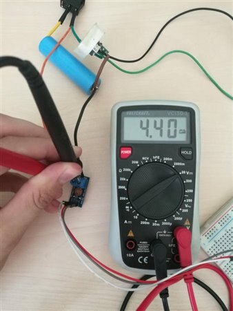
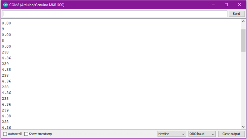
On the serial monitor the moment where I turned on the switch can be seen with the voltage jump. On the voltmeter I was getting voltages from 4.38-4.40 while the Arduino was showing 4.36-4.38, which is accurate enough for my needs with this project.
Summary
The deadline has come real close real fast! I've sorted all of the electronics on their own, so all that's left is to connect everything together and combine and modify the codes I've written until now. As for the project itself, there is one more thing I have to do for it to function and that is the second part for the slider mechanism where I will tackle mounting, adjusting and testing the servo, as well as the key lock mechanism so the key stay extruded. After that all that's left is the final assembly to test out the first prototype! Thank you for reading the blog, hope you liked it!
Milos