


Ancilliary Energy Storage Unit
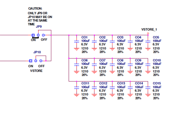
As mentioned at the end of Part 001 the EHSTG kit comes with a bank of capacitors can be configured as VSTORE for the LTC3108 TEG energy harvester or as an energy storage bank for the outputs of then energy harvesters (including the LTC3108).
This capacitive bank is used to accumulate the energy as electric charge.
When configured to store the outputs to get longer running times its size can be increased in capacitance with the addition of some more capacitors but it does have a side effect.
The side effect is that it requires more energy to reach the operating voltage and thus may require more time for the energy harvesters to accumulate the necessary energy to reach the operating voltage threshold.
V = Q/C
This also illustrates a second point of not all of the charge accessible by a device with a minimum operating voltage level because the output voltage is directly proportional to charge.
The full effect delay is only applicable when the bank is totally empty. This will occur at the very first attempt or an attempt after the bankt has emptied out due to energy leakage which usually over a prolonged time on inactivity.
Ideally this energy bank should;
- Reach the operating voltage quickly to enable the connected device to commence operation.
- Continue accumulating charge that is being harvested that is not being consumed whilst the connected device is in operation.
- Not to commence operation until sufficient energy has been accumulated.
(BTW- the LTC3108 can do this to some degree.)
If we simply connect a 1 Farad capacitor to the inbuilt bank (15 x 100uF), its capacitance rises from .0015 Farads to 1.0015 Farads.
And assuming we are energy harvesting at a constant charge rate it will roughly take 667 (1.0015/.0015) times longer before the POWERGOOD signal is asserted to turn on from an empty state.
I ran a rough experiment to confirm this. I loaded the STK3700 with the default INTEMP application and measured how long it took the Solar energy harvester to start it
- a. with just the inbuilt bank of capacitors (.0015F)
- b. with a 1F capacitor added to it.
There's not such thing as an unsuccessful experiment but by results confirmed my findings.
With morning sunlight and
With just the inbuilt bank of capacitors operation was pretty close to immediate.
With the 1F capacitor added it took about a couple of minutes.
As for operation the light was removed,
With just the inbuilt it ran for a few seconds.
With the 1F capacitor added it ran for ages and gave up on monitoring it.
I exposed the unit to sunlight again and this time the unit started much quicker for both configurations.
The residual charge in the capacitors remained thus enabling it to reach its operating voltage much quicker.
For the IR remote control, the 1F capacitor addresses the energy accumulation and the Hand crank is used to accelerate its charging to an operational state and as an alternative energy source.
However this solution is not always feasible.
Particularly addressing the unusable accumulated energy from the abovementioned configuration.
To do this a DC-DC step up converter is required. This requires additional circuitry and introduces new energy losses.
I have a suitable solution that I used with in the Wireless Power Solution RoadTest where the design;
a. Decides to use input power or reserve power
b. Convert the voltage of the reserve power to the nominated voltage.
A brief of it is here. http://www.element14.com/community/groups/wireless-power-solution/blog/2012/12/09/its-alive-part-018
All that needs to change is some tuning to enable it to use energy harvested power rather than wireless power.
There are other feasible techniques.
Remember that V=Q/C so if we can reduce C (the capacitance) with out affecting Q (the stored charge) we can increase its voltage.
All that is needed is a circuit to detect the voltage and reconfigure the capacitance accordingly and the ramifications thereof.
One method is by having an array of capacitors and switching their connection configuration.