I would like to sum up all the work I have done in one post for those who did not follow this RoadTest and do not want to go through all the posts one by one.
Project description
The other night I was making diner in the kitchen and I saw a blinking red LED on my carbon monoxide detector, indicating that I need to replace batteries. That is when I realized that some energy harvesting technique should do the trick for me next time with a help of some hack. These types of alarms are usually either mains or battery operated. In stores you can also get double powered ones (battery as the buffer, secondary supply). I do not have any power jacks available next to the places where I put my detectors (basement, kitchen and bathroom) and long cords wouldn’t look nice, so I use battery ones. As for energy harvesting I cannot use solar charger in my basement or vibration energy in any of the places, but still I could employ some Peltier modules to get energy from temperature difference in all the places at home. Later on I did put new batteries in my detector and got distracted by other projects and forgot about this energy harvesting idea for some time. Luckily, I was going through some topics on Energy Micro forum and I saw the energy harvesting RoadTest link.
Now, I present to you the final demo project movie. Later on you can check description about my struggles with energy harvesting.
The beginnings
I got my energy harvesting kit and I starter to test it. Everything on the board worked great.
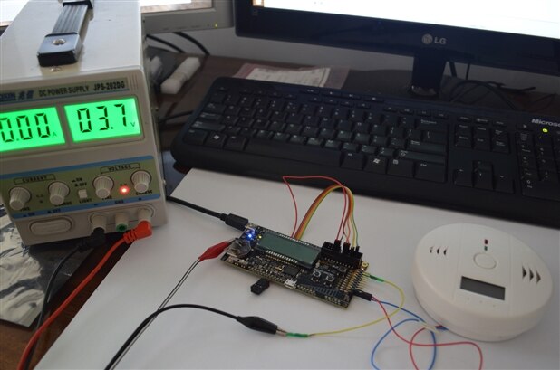
I wanted to check how much energy does a simple CO detector consume, so I cracked one open and saw its guts.
Additionally, I checked the energy consumption with a help of Energy Micro (now Silicon Labs) STK board. It has the energy debug module (AEM) and you can check the current draw in real time on your computer. If you are interested how to do that, please check one of my previous posts.
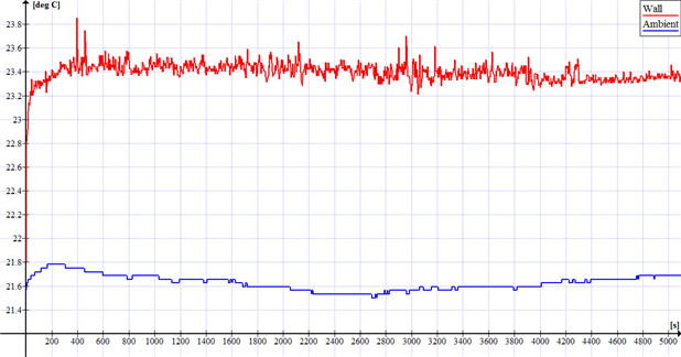
The average current consumption was about 500 uA. For standard mains supply that is almost nothing, but if you want the device to run on battery for couple of years or to be supplied from energy harvesting, you have to get your hands dirty and cut this consumption by at least 90%. And this is where the magic happens. I started to investigate from where I can get the free energy from temperature difference. My fists guess was: the walls. When you touch some wall you have a feeling that it is chill. But as it turned out it is just how you feel the temperature through your skin. In the matter of fact I checked some wall and ambient temperature and there was the difference, but only slight one.
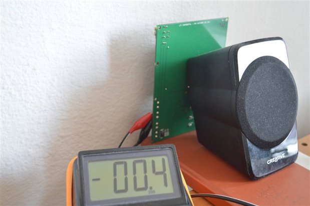
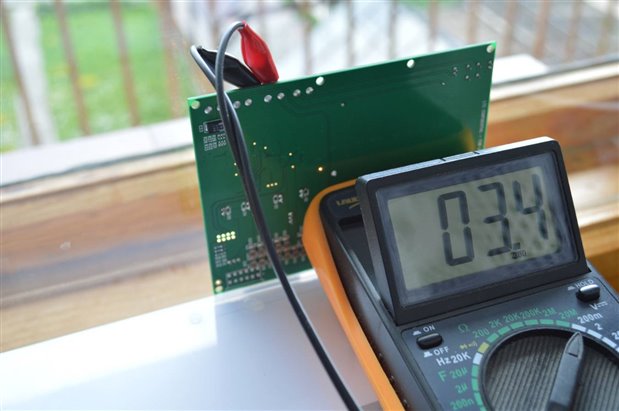
I thought to myself: “but there is still the difference, maybe I can get at least some energy from this?”. As it turned out, I could … but only for short period of time. The thermal conductance between Peltier module was faster than the one inside the wall, so after some time the difference in temperature between the wall and ambient was practically none. I also investigated if I could bet something from a glass window, but it was also a dead end.
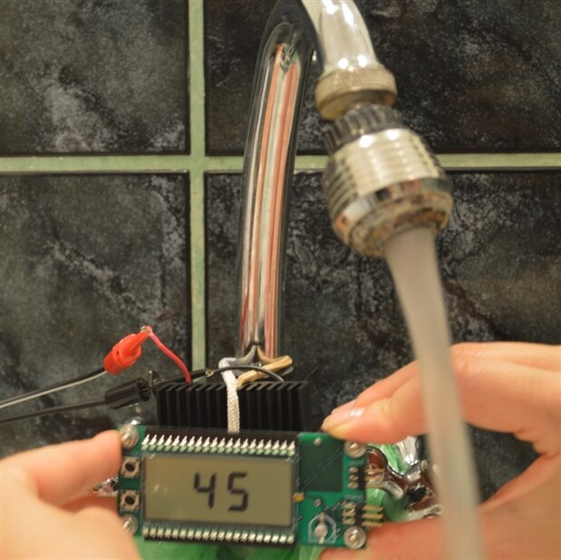
Then I tested the energy harvesting from hot water tap and that was it. I got satisfying results and I went with that solution. You have pipes with hot water, pretty much in all places where you need your CO detector: kitchen, bathroom, cellar, etc. If you are interested in precise data of this energy harvesting, please check this post.
The thing that was a little bit unexpected for me was that even after you turn off the tap, the pipe is still hot and you can harvest the energy – in that way, the heat in the water is not wasted. Check out the Peltier voltage timeplot after the tap was turned off.
Sensing unit
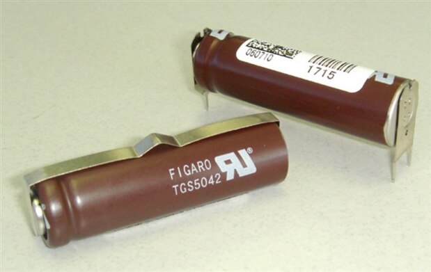
To sense carbon monoxide concentration, I took many sensors into consideration. The one I have chosen for my design is TGS 5042 from Figaro.
There are 3 main reasons that this sensor is perfect for my application:
- This is an electrochemical sensor – it does not need power supply. It is filled with some chemicals which in reaction with carbon monoxide produce current and the sensor works as current source. Plus, other gases and temperature (especially home environment temperature range) has almost zero influence on it and the lifetime is minimum 7 years.
- It does not need any fancy external chips and circuits. Carbon monoxide concentration is linear to the current value.
- It is designed for battery operated systems. It has only two lead and there is no need to heat it up (5V) before reading the measurements. Additionally, the reaction time for the gas concentration is below 60 seconds, which is very important for people safety.
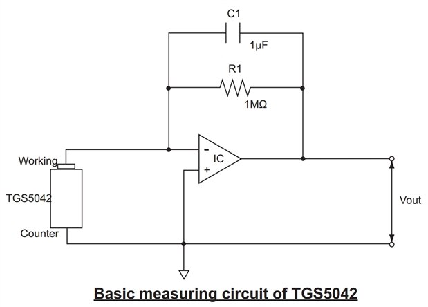
The datasheet suggests this measurement circuit (current-to-voltage converter):
I tested it and it works great, but … it requires external opamp with dual supply. With energy harvesting there is a problem with energy availability so with adding additional charge pump or other DC/DC (inverter) we would lose some vital energy. That is why I wanted to use the opamp which is already inside the EFM32 chip on the STK. The problem is that it is only single supply opamp. So, I proposed another measurement circuit:
The 1k resistor next to the sensor is for protection purposes. The datasheet says that the sensor should not be polarized with voltages above +/-10mV (when storing the sensor, datasheet suggests to short-circuit it). While my circuit is operational, there would be no problem, but I plan to turn off everything that I can, whenever I can to save power. That is why I have included this 1k resistor to protect the sensor (even in a high carbon monoxide concentration) when the internal opamp is disabled. I have used the opamp in non-inverting configuration (cause there is only one power supply and I do not want to make any external circuits for virtual ground) and that is why I had to invert the sensor leads. The sensor with STK is operational. The voltage to ppm conversion can be applied with the linear graph from the datasheet. The output voltage from the opamp takes form of: Vout = Isensor * R3 * ((R1 / R2) +1). It can be read with EFM32’s ADC. The gain is about 106 with the circuit I propose, so the 3V single supply amp can detect concentration far above 1000 ppm which is more than sufficient for home appliences.
I tested it and it worked great. Below, you can check the movie that shows the Voutput from the EFM32 opamp (non-inverting amplifier configuration), when the sensor is put inside the jar filled with CO. The first time the CO concentration was low because I put the paper towel inside just after it started to burn. The second time the Voutput equals the supply voltage because the CO concentration was above 1700ppm. 1V output is about 500ppm. After the first test when I took the sensor out, one lead disconnects so you can see that voltage goes off the scale, but the second time it is ok. You can see that in high CO concentrations the sensor’s response is very fast - couple of seconds (in datasheet max response is 60 sec. but for lower concentrations). When I opened the jar, the CO was quickly clearing out and the Voutput was dropping soon after.
Code
Then I moved to developing the energy friendly code for the microcontroller. I finished writing and testing the code for my project. Previously, I measured the average current consumption of a simple, cheap CO detector to be around 500 uA (@3,3 V) – that is being consumed by the whole standby and sensing functionality. This is a way over what I can supply from the TEG when harvesting energy from hot water tap. That is why I used Energy Micro STK with EFM32 Giant Gecko on board to create my own CO detector device. Before you continue to read the rest of this post, try to guess what average current consumption I did manage to achieve. Later on you can compare your estimation with my score and that will give you the idea how low-power the EFM32 family really is. But let's start from the beginning.
The device uses Figaro TGS 5042 carbon monoxide sensor. The datasheet says that the max response for even small CO gas concentrations is around 60 sec. In large CO concentrations, for instance over 500 ppm, the sensor response time is only couple of seconds. So, the whole device should be in some sleep mode. And here starts the fun! The EFM32 chip's EM4 (Standby mode) comes very handy. In this mode - according to Energy Micro data - chip draws only 20 nA. But I needed to implement some extra functionality. The Giant Gecko comes with RTC and BURTC (BackUp RTC). BURTC can operate in EM4 and wake up the chip when time compare event occurs. Ultra Low Frequency Clock (internal - 2 kHz) can be used with the BURTC in order to use as little energy as possible. This clock is usually not exactly 2 kHz, so if you would like to use it in your application, you should calibrate it with the oscilloscope and check the temperature stability data in the datasheet to get the best possible time accuracy.
Having the BURTC to wake up the processor every 60 seconds to check the CO sensor response is one thing, but the CO detectors usually do have the TEST button. Thus, EFM32 Giant Gecko also provides the possibility to wake up the processor from EM4 with an external pin interrupt (apart from the reset pin) and this is exactly what I have implemented. To sum up: the device is in the most energy friendly mode EM4 for approximately 60 seconds or less, if one press the TEST button.
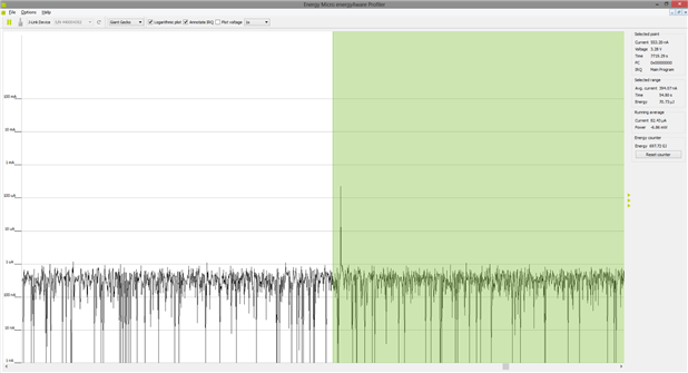
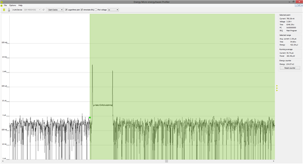
After a wake up, EFM32 checks the CO gas concentration and: if the concentration is higher than some threshold level (right how I set it on 35 ppm) or the wakeup is a result of the TEST button, the value in ppm is presented on LCD; if the TEST button was not pressed of the concentration is lower than the threshold, the result is not being displayed. Regardless of the case, the EFM32 goes into EM4 again. Below you can check two graphs, which represents the current consumption from the mentioned cases.
The average current consumption in the first case is around 2.4 uA and in the second case only around 400 nA. Is it even close to what you have guessed? In the next graph you can check the close up of current consumption between the wake up and going back to EM4 (case where the ppm value is being displayed). The whole action takes around 1.35 sec. The average current consumption in this time is around 80 uA.
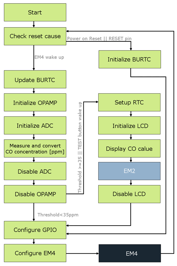
80 uA is not so little for the energy harvesting power supply, but since this occurs only once every 60 seconds and takes 1.35 sec, it is bearable. Nevertheless, it could have been far more than 80 uA – even couple of mA. The reason why the value is so low is that some other energy friendly coding, functionality and other energy modes were implemented.The picture below presents the basic dataflow of the code.
After the wake up the reset cause is being checked. If the reset was not caused by any of the implemented EM4 wake up methods, in other words – the cause of the wake up is Power on Reset or the RESET pin – BURTC is being initialized to work on 2 kHz Ultra Low Frequency Clock in EM4 and to wake up after 60 seconds. Also, the GPIO Port F, Pin 2 is being configured as Pulled Input (filtered) in order to allow wake up with the TEST button. If you would like to use this feature in your project, make sure that you also have enabled GPIO pin mode retention in EM4. It will allow the chip to use this GPIO wake up feature and also to keep some GPIO pins you set, for example to hold high or low the CS pin of some chip (i.e. memory or accelerometer). Enabling this feature will cause higher current consumption in EM4, but you will save probably more energy than if you would leave the pins floating. In the end, the EM4 mode is configured and the chip goes into it.
However, if the wake up was caused by the BURTC interrupt of the TEST button, the BURTC peripheral is being updated and the measurement stage begins. The Opamp is being initialized in the non-inverting mode. Then, ADC (channel 2) is being initialized, the analog value is converted 5 times and the mean value is calculated. Next, this value is put into the equation to get the CO gas concentration in ppm. Then, ADC and Opamp are being disabled.
Right now, I would like to explain what I use for the ADC reference. The EFM32 can use couple of sources as a reference (check the reference manual). Usually, I use the supply voltage of the chip. However, when using energy harvesting converter and some storage (supercaps), the supply voltage can be unstable. In my case, when the water is turned off, the device would be supplied from the supercap and in time the voltage will drop. So, I have decided to use the internal EFM32 5 V reference source. But remember that this voltage is only available when the supply voltage of the chip is not less than 2.5 V. In my project, the 5 V reference still gives me the desired resolution.
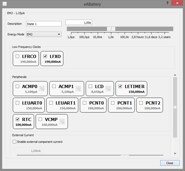
If the value of concentration is less than a 35 ppm threshold, the value is not being displayed. But, if it is 35 ppm and more or the wake up was caused by the TEST button, the RTC is being configured to count the duration of displaying the value in ppm on the LCD. The LCD driver is being initialized, the value is displayed and the chip goes into EM2 mode for the time of displaying to save energy. After some short period of time, the RTC wakes up the chip and the LCD driver is being disabled. Here is a tip for you. If you need to count time in EM3 mode, you can use the Low Energy Timer in EFM32 (with ULFRCO) instead of the RTC to save energy. My device have to stay in EM2, because of the LCD driver to I use RTC. I could also use Low Energy Timer in EM2 but it uses more current than RTC in this mode.
After this I had to modify the code to add a delay after the OPAMP is being turned on. There is a capacitor in feedback circuit to prevent glitches, so it needs time to charge and show correct output voltage. During this delay, uC goes into EM obviously. This change causes bigger current draw, but still, this happens only once a minute for a short period of time.
I know I can still go lower on the average current consumption by more tailoring the code (tweaking prescalers, checking the disassembly, not use API for EFM32, etc.), but this would not give me a significant drop, because for most of the time the chip is in EM4 and that is the lowest it can get. That is why I think of this code as a version 0.9. I have uploaded the source code for you to check and you can add how you can inform about crossing the concentration threshold (simple buzzer, UART transmission, RF, etc) if you would like to build this detector.
Final round
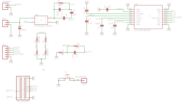
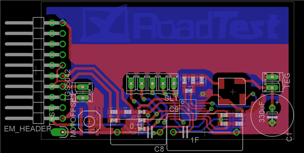
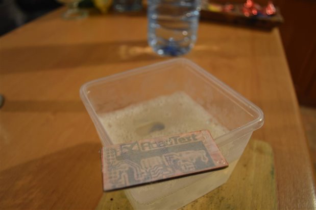
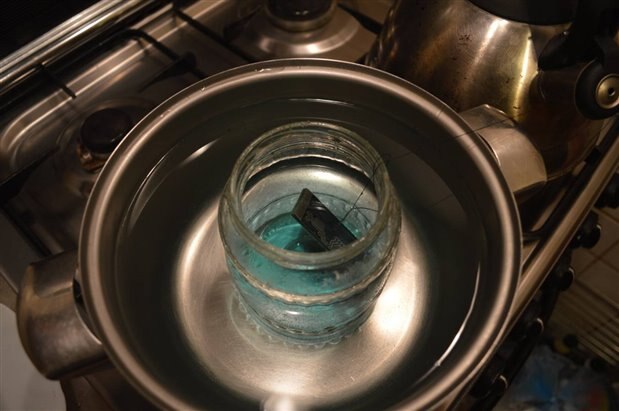
Since deadline was approaching fast, I did not have time to order the PCB. That is why I had to do it by myself in the old fashion iron way. Here are some pictures of schematic, board and the etching process.
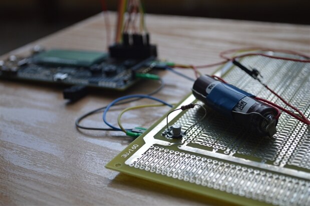
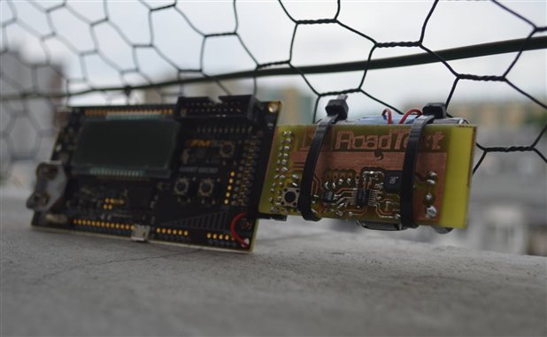
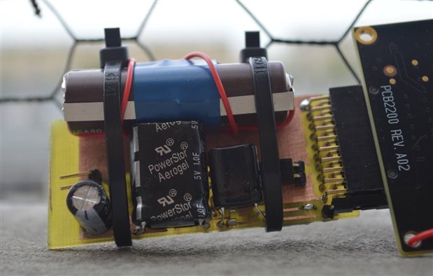
I soldered and tested my board and I must say – it works great! Here are some pictures of the whole thing: detector, harvester and STK with uC.
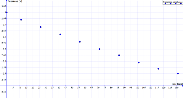
I did some energy tests. The output of the harvester chip has 0.1 F supercap. I used LTC3108-1, so the output is 3 V. As I mentioned, I use internal EFM32 5V reference, so the usable voltage for me is 2.5-3 V. Below, there is a graph of discharge process. It takes more than 2 h to drain the 0.1 F supercap from 3 to 2.5 V.
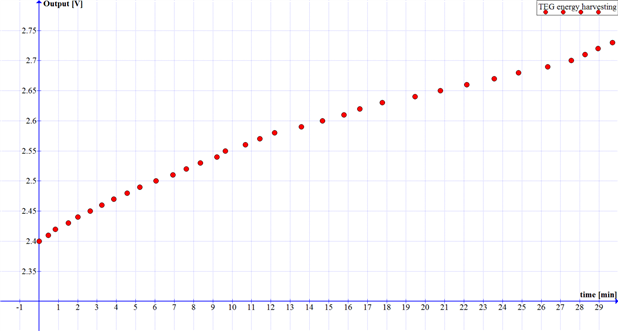
Additionally, I did some energy harvesting time test. The charging graph from 2.4 to 2.7 V is presented below.
To compare, the charge/discharge time ratio from 2.5 to 3 V is 1/3. I thought to myself I could be better, but I tested the device over a whole day where I was doing some house choirs: washing dishes, cleaning, cooking, plus two baths and I have to say that after a day the voltage was still 3 V and even some extra energy was saved in STORE capacitor – I used 1 F supercap.
My other observations:
- If you use your hot water tap a lot during the day, the system works great. When not so often, bigger (or even couple) Peltier module and radiator may come handy.
- When the output supercap and the STORE supercap are fully charged, the device can autonomously work for almost 1.5 day.
- Be aware where you put the radiator. If it is right above the sink, the heat from hot water will influence the ambient temperature and TEG will not be as effective as it could be.
- The stable 70 mV Peltier voltage shows really quick after you turn the water on, but the tap stays warm for at least couple/tens of minutes, so I noticed that it is more efficient to use the tap often, but for short periods.
- As Victor (other RoadTest contestant) mentioned in one of his posts, there is a problem with starting the EFM32 because of the leakage current. The LTC comparator and FET is a solution, but I would like to use something else. Since the CO detector is a safety device it should have power supply all the time, even if the hot water is not used for some time. That is why I would like to use harvester with buffered power supply from a battery. I used this in one of my projects and it worked great. You just have to use another LTC (the one without -1 at the end), the 3 V battery and two Schottky diodes.
Final thoughts
- Energy harvesting is hard, but very interesting.
- You have to think about everything: low-energy component use, energy optimized analog circuits, energy saving oriented code in uC, low-power sensors, DC/DC converters, energy storage, energy harvesting technique, possibilities and restrains. If you miss even one of them, you will fail.
- Energy harvesting is not for every design.
- Make use of unique features and exploit the best way scenarios.
- Think outside the box.
If you are interested in this sensor, please chech the source code files, Eagle schematic and board layout files attached to this post.







Top Comments
-

sharath24
-
Cancel
-
Vote Up
0
Vote Down
-
-
Sign in to reply
-
More
-
Cancel
Comment-

sharath24
-
Cancel
-
Vote Up
0
Vote Down
-
-
Sign in to reply
-
More
-
Cancel
Children