


The last post was very short, just a picture of the layout of my board, becaus I really, really, really wanted to get into my bed. Which I did. I will now describe what I've done the last few days.
Datasheet reading
In my second-last post I pointed out some specifics about the LTC3108. After configuring that, I went on to design the schematic for the EFM32. At first I was feeling a bit awkward about using the EFM32 Giant Gecko series for the simple task I was performing, and especially for having to use such a large device in pin numbers. Then when I started looking for LCD's I found out that most pins were actually going to be used. I've never designed something driving an LCD directly, and now that I selected a very small display ('100 count'), I realized how fast an LCD eats through the available pins.
A big compliment is in its place for EnergyMicro's documentation. I've always praised Atmel for having both good datasheets and good application notes on peripherals, and I can add EnergyMicro to the list of chip vendors that understood how to make an engineer happy! Although SimplicityStudio (the tool to select documentation and keep stuff up to date) is not my favorite application, a simple Ctrl-F action in the directory where the docs are stored helps me tremendously. The datasheet about the LCD driver revealed a lot of info to me (didn't know you had to drive LCD's with AC waveforms), and gave me ample background info on the internals of the chip. I've selected a very simple display with only one 'common', but the EFM32 enables multiplexing of displays with several commons, while maintaining a zero-DC-bias, and doing this in low power mode.
Coming to low power: before starting this RoadTest Challenge I already knew EnergyMicro from name, and knew they're targeting low power applications. I now know how serious they are about it.... Every aspect of the chip is designed with low power in mind, and almost all features can be switched off to save power, or be enabled to run in a low power mode. To return to the LCD driver: for some displays the output voltage needs to be higher than the VCC provided. The EFM32 has an internal boost converter for this (just need to add two capacitors on IO pins), which can be enabled or disabled. Also, animations in the display can be kept running in low power modes, without intervention of the CPU. All these features are targeted at either using as little energy as possible by switching unneeded stuff off, or taking care that WHEN you need them, you can do so in a low power mode. I think Gelmi's posts have already shown quite a bit about these possibilities, and the optimizations you can do in that area.
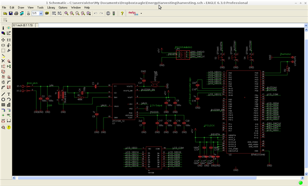
Schematic
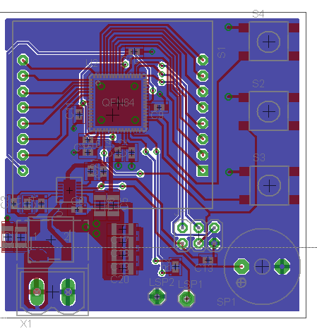
layout, 49x49mm
Doing the layout
When doing the layout I considered two things: making a good layout for the switching converter, and getting the layout done in time  I hope I haven't made any screw-ups in the footprints!
The layout of the LTC3108 was aided by the guidelines in the datasheet (come to think about it: LT is also good at datasheets!). I've created a local GND plane under and around the DC/DC converter, and tied it to the 'main' GND plane in one spot. The goal of this approach is that all local switching currents will go through the local plane, preventing currents from going through the GND plane on the bottom layer. This way, the bottom layer GND will remain 'clean' , while the DC/DC converter will have a low-resistance, low- inductance path where current peaks are expected.
The assignment of the pins for the LCD was changed to make routing as simple as possible. I've seen that there is a way to convert the EM libraries to use other displays, I'll have to see whether I can use those to control my display, or that I'm going to write my own routines.
There's one part that really got my mind messed up, and that was the pinning of the transformer; in the end I looked up how it was in the schematic and layout of the demonstrator board, and took care that it was equal. This is very important, as the 'dots' of the transformer have to be aligned correctly to get the right polarity on the secondary winding.
BIG THANKS TO WUERTH
A big 'thank you' goes out to Wuerth; they're not only enabling this RoadTest Challenge by making the energy harvesting to go kit, but also agreed to help me fabricate my PCB. Around the 7th of July I can expect a small parcel from WE-direkt that contains my 2-layer design. Without them, I wouldn't have had the possibility to finish this in time. Thanks again!
What's next?
Now that I've got to wait for a week, I'll have to make a partlist, and maybe already prepare some code to use the new LCD. Also, I'll do some simulations to look at the behaviour of the LTC3108. Stay tuned!


