element14 Community
element14 Community
    Register Log In
  • Site
  • Search
  • Log In Register
  • Community Hub
    Community Hub
    • What's New on element14
    • Feedback and Support
    • Benefits of Membership
    • Personal Blogs
    • Members Area
    • Achievement Levels
  • Learn
    Learn
    • Ask an Expert
    • eBooks
    • element14 presents
    • Learning Center
    • Tech Spotlight
    • STEM Academy
    • Webinars, Training and Events
    • Learning Groups
  • Technologies
    Technologies
    • 3D Printing
    • FPGA
    • Industrial Automation
    • Internet of Things
    • Power & Energy
    • Sensors
    • Technology Groups
  • Challenges & Projects
    Challenges & Projects
    • Design Challenges
    • element14 presents Projects
    • Project14
    • Arduino Projects
    • Raspberry Pi Projects
    • Project Groups
  • Products
    Products
    • Arduino
    • Avnet & Tria Boards Community
    • Dev Tools
    • Manufacturers
    • Multicomp Pro
    • Product Groups
    • Raspberry Pi
    • RoadTests & Reviews
  • About Us
  • Store
    Store
    • Visit Your Store
    • Choose another store...
      • Europe
      •  Austria (German)
      •  Belgium (Dutch, French)
      •  Bulgaria (Bulgarian)
      •  Czech Republic (Czech)
      •  Denmark (Danish)
      •  Estonia (Estonian)
      •  Finland (Finnish)
      •  France (French)
      •  Germany (German)
      •  Hungary (Hungarian)
      •  Ireland
      •  Israel
      •  Italy (Italian)
      •  Latvia (Latvian)
      •  
      •  Lithuania (Lithuanian)
      •  Netherlands (Dutch)
      •  Norway (Norwegian)
      •  Poland (Polish)
      •  Portugal (Portuguese)
      •  Romania (Romanian)
      •  Russia (Russian)
      •  Slovakia (Slovak)
      •  Slovenia (Slovenian)
      •  Spain (Spanish)
      •  Sweden (Swedish)
      •  Switzerland(German, French)
      •  Turkey (Turkish)
      •  United Kingdom
      • Asia Pacific
      •  Australia
      •  China
      •  Hong Kong
      •  India
      •  Korea (Korean)
      •  Malaysia
      •  New Zealand
      •  Philippines
      •  Singapore
      •  Taiwan
      •  Thailand (Thai)
      • Americas
      •  Brazil (Portuguese)
      •  Canada
      •  Mexico (Spanish)
      •  United States
      Can't find the country/region you're looking for? Visit our export site or find a local distributor.
  • Translate
  • Profile
  • Settings
Energy Harvesting Design Challenge
  • Challenges & Projects
  • Design Challenges
  • Energy Harvesting Design Challenge
  • More
  • Cancel
Energy Harvesting Design Challenge
Blog Energy optimized code (II)
  • Blog
  • Forum
  • Documents
  • Files
  • Mentions
  • Sub-Groups
  • Tags
  • More
  • Cancel
  • New
  • Share
  • More
  • Cancel
Group Actions
  • Group RSS
  • More
  • Cancel
Engagement
  • Author Author: gelmi
  • Date Created: 29 Jun 2013 10:21 AM Date Created
  • Views 628 views
  • Likes 1 like
  • Comments 0 comments
  • low_power
  • heat
  • low_energy
  • thermal_energy
  • 32_bit
  • linear
  • temperature
  • enery_efficiency
  • energy_harvesting
  • thermal
  • efm32
  • peltier
  • energy_micro
  • self_powered
  • kit
  • energy_saving
  • consumer_electronics
  • energy_harvesting_challenge
  • energy_harvesting_source
Related
Recommended

Energy optimized code (II)

gelmi
gelmi
29 Jun 2013

In this post I would like to describe what the code does when the chip is woken up once a minute or when the TEST button is pressed. I will mention only the most important parts of the code. If you would like to investigate it more, you can check source files which are uploaded with this post. The picture below presents the basic dataflow of the code.

image

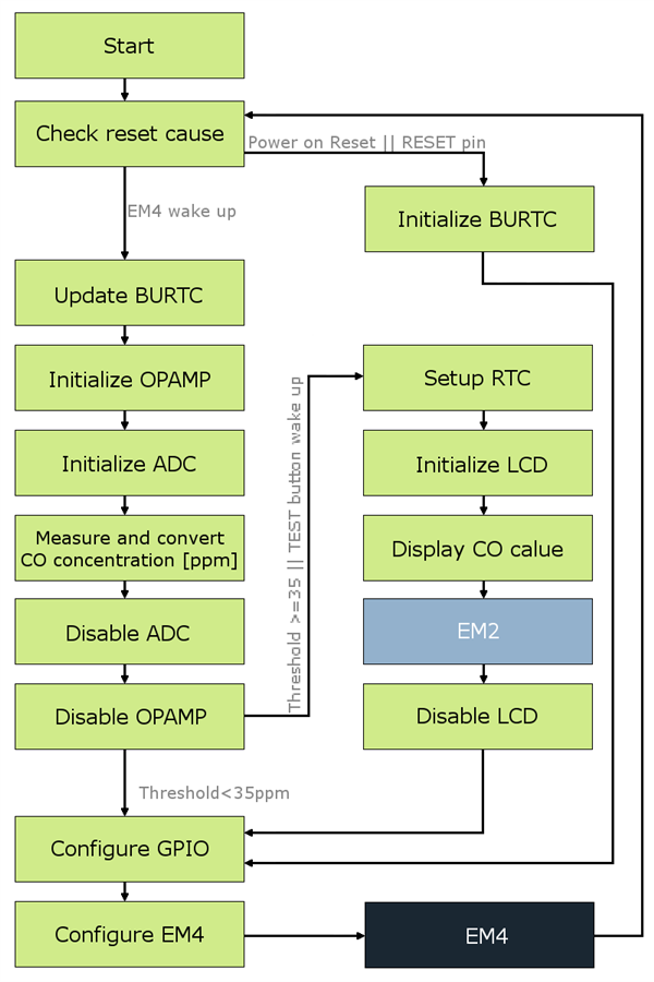
After the wake up the reset cause is being checked. If the reset was not caused by any of the implemented EM4 wake up methods, in other words – the cause of the wake up is Power on Reset or the RESET pin – BURTC is being initialized to work on 2 kHz Ultra Low Frequency Clock in EM4 and to wake up after 60 seconds. Also, the GPIO Port F, Pin 2 is being configured as Pulled Input (filtered) in order to allow wake up with the TEST button. If you would like to use this feature in your project, make sure that you also have enabled GPIO pin mode retention in EM4. It will allow the chip to use this GPIO wake up feature and also to keep some GPIO pins you set, for example to hold high or low the CS pin of some chip (i.e. memory or accelerometer). Enabling this feature will cause higher current consumption in EM4, but you will save probably more energy than if you would leave the pins floating. In the end, the EM4 mode is configured and the chip goes into it.

However, if the wake up was caused by the BURTC interrupt of the TEST button, the BURTC peripheral is being updated and the measurement stage begins. The Opamp is being initialized in the non-inverting mode. Then, ADC (channel 2) is being initialized, the analog value is converted 5 times and the mean value is calculated. Next, this value is put into the equation to get the CO gas concentration in ppm. Then, ADC and Opamp are being disabled.

Right now, I would like to explain what I use for the ADC reference. The EFM32 can use couple of sources as a reference (check the reference manual). Usually, I use the supply voltage of the chip. However, when using energy harvesting converter and some storage (supercaps), the supply voltage can be unstable. In my case, when the water is turned off, the device would be supplied from the supercap and in time the voltage will drop. So, I have decided to use the internal EFM32 5 V reference source. But remember that this voltage is only available when the supply voltage of the chip is not less than 2.5 V. In my project, the 5 V reference still gives me the desired resolution.

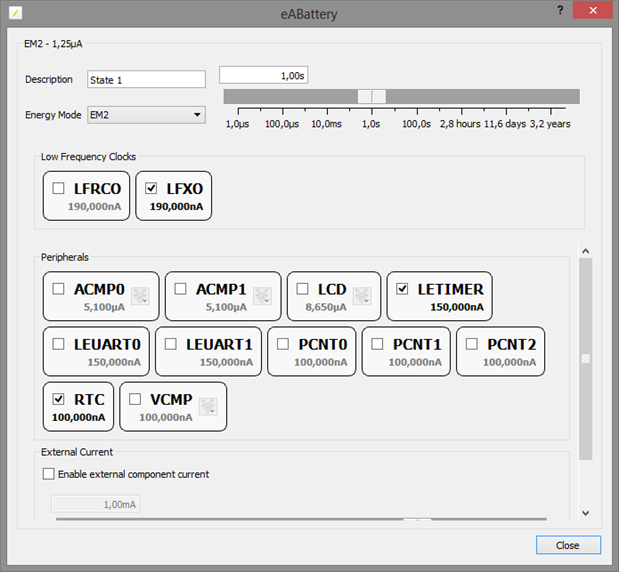
If the value of concentration is less than a 35 ppm threshold, the value is not being displayed. But, if it is 35 ppm and more or the wake up was caused by the TEST button, the RTC is being configured to count the duration of displaying the value in ppm on the LCD. The LCD driver is being initialized, the value is displayed and the chip goes into EM2 mode for the time of displaying to save energy. After some short period of time, the RTC wakes up the chip and the LCD driver is being disabled. Here is a tip for you. If you need to count time in EM3 mode, you can use the Low Energy Timer in EFM32 (with ULFRCO) instead of the RTC to save energy. My device have to stay in EM2, because of the LCD driver to I use RTC. I could also use Low Energy Timer in EM2 but it uses more current than RTC in this mode.

image

I know I can still go lower on the average current consumption by more tailoring the code (tweaking prescalers, checking the disassembly, not use API for EFM32, etc.), but this would not give me a significant drop, because for most of the time the chip is in EM4 and that is the lowest it can get. That is why I think of this code as a version 0.9. I have uploaded the source code for you to check and you can add how you can inform about crossing the concentration threshold (simple buzzer, UART transmission, RF, etc) if you would like to build this detector.

Attachments:
co_detector[29.06.2013].zip
  • Sign in to reply
element14 Community

element14 is the first online community specifically for engineers. Connect with your peers and get expert answers to your questions.

  • Members
  • Learn
  • Technologies
  • Challenges & Projects
  • Products
  • Store
  • About Us
  • Feedback & Support
  • FAQs
  • Terms of Use
  • Privacy Policy
  • Legal and Copyright Notices
  • Sitemap
  • Cookies

An Avnet Company © 2025 Premier Farnell Limited. All Rights Reserved.

Premier Farnell Ltd, registered in England and Wales (no 00876412), registered office: Farnell House, Forge Lane, Leeds LS12 2NE.

ICP 备案号 10220084.

Follow element14

  • X
  • Facebook
  • linkedin
  • YouTube