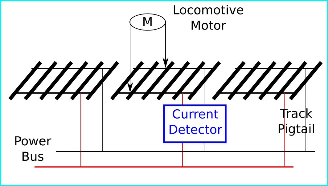
The goal of this challenge is to use the MAX40080 Current Sense Amplifier to detect the locomotive of a model train passing over a section of track rail.

In model railroading, determining if there are rail cars on a section of track is called Block Detection. There are a few methods that are used on model railroad layouts to accomplish the task. My plan is to look at current sense as a detection method.

There are two types of control systems for model train layouts. Direct Current (DC) and Digital Command and Control (DCC).
In the DC system, a DC voltage is applied to the power bus that supplies each isolated section of track through pig tails. The motor in the train locomotive picks up DC power from the track rails. The magnitude of the voltage determines the speed of the train. The polarity of the DC voltage determines the direction of travel for the locomotive.
In the DCC system a steady voltage is applied to the power bus. The power bus provides power to the locomotive and also acts as a communication path between a controller and the decoder inside the locomotive. Pulse signal are sent along the communication path as coded instruction picked up by the decoder. The decoder gets power from the track rails to operate. It controls the power used to drive the motor. In the DCC system, two signals that are sent to locomotive decoders are speed control and direction of travel.
The locomotive motor draws current from the rails. Track rails are isolated from each other, detecting current in a section of track will show the locomotive is present in that section of track.
At a cursory glance, this exercise seems pretty basic for the MAX40080 Current Sense Amplifier, simply detect the current drawn by a motor. The challenge becomes the model train control system.
The DC system varies the voltage and polarity of the power bus in order to control speed and direction of the locomotive. These are two parameters that are used in the current sense process. How will the variations impact performance?
For testing three speeds, slow, medium and fast will be used. Slow speed will be the voltage that just starts the locomotive moving and fast being the highest speed the locomotive operates at. Medium being some value in between. In this experiment, the fast speed is capped at 12VDC. The slow speed will be determined based on the locomotive used.
Besides variable voltage applied to the current sensor, the polarity of the power bus will change as the direction of the locomotive changes. How will the variations impact performance?
The DCC control system has its nuances that need to be considered for current detection. The voltage applied to the power bus and the polarity of the voltage in this system are constant. The decoder controls speed and direction of the locomotive. The aim is to show that the power bus provides more current as the speed of the locomotive varies. Direction of the locomotive travel should have no impact.
In addition, the DCC system uses the power distribution mechanism as a communication path. Will this impact the performance of the current sense?
To summarize, here are the conditions for examining the MAX40080 Current Sense Amplifier across the two systems:
DC system
-varied voltage
-varied polarity
DCC system
-constant voltage
-varied current
-communication signals
When I initially looked at this challenge, my first question was, how is the MAX40080 Current Sense Amplifier installed? Here is the approach I am going to take. Dear reader, if you see something amiss, please provide feedback.

With the MAX40080 Current-Sense Amplifier installation resolved a python script to detect the current will be required. I’m making an assumption the details for the script as well as installation and configuration of the Click 6, MAX40080 Current-Sense Amplifier model to the Raspberry Pi are available. Documentation suggests prior development material is provided through the vendor’s resources that can support the board.
