element14 Community
element14 Community
    Register Log In
  • Site
  • Search
  • Log In Register
  • Community Hub
    Community Hub
    • What's New on element14
    • Feedback and Support
    • Benefits of Membership
    • Personal Blogs
    • Members Area
    • Achievement Levels
  • Learn
    Learn
    • Ask an Expert
    • eBooks
    • element14 presents
    • Learning Center
    • Tech Spotlight
    • STEM Academy
    • Webinars, Training and Events
    • Learning Groups
  • Technologies
    Technologies
    • 3D Printing
    • FPGA
    • Industrial Automation
    • Internet of Things
    • Power & Energy
    • Sensors
    • Technology Groups
  • Challenges & Projects
    Challenges & Projects
    • Design Challenges
    • element14 presents Projects
    • Project14
    • Arduino Projects
    • Raspberry Pi Projects
    • Project Groups
  • Products
    Products
    • Arduino
    • Avnet Boards Community
    • Dev Tools
    • Manufacturers
    • Multicomp Pro
    • Product Groups
    • Raspberry Pi
    • RoadTests & Reviews
  • Store
    Store
    • Visit Your Store
    • Choose another store...
      • Europe
      •  Austria (German)
      •  Belgium (Dutch, French)
      •  Bulgaria (Bulgarian)
      •  Czech Republic (Czech)
      •  Denmark (Danish)
      •  Estonia (Estonian)
      •  Finland (Finnish)
      •  France (French)
      •  Germany (German)
      •  Hungary (Hungarian)
      •  Ireland
      •  Israel
      •  Italy (Italian)
      •  Latvia (Latvian)
      •  
      •  Lithuania (Lithuanian)
      •  Netherlands (Dutch)
      •  Norway (Norwegian)
      •  Poland (Polish)
      •  Portugal (Portuguese)
      •  Romania (Romanian)
      •  Russia (Russian)
      •  Slovakia (Slovak)
      •  Slovenia (Slovenian)
      •  Spain (Spanish)
      •  Sweden (Swedish)
      •  Switzerland(German, French)
      •  Turkey (Turkish)
      •  United Kingdom
      • Asia Pacific
      •  Australia
      •  China
      •  Hong Kong
      •  India
      •  Korea (Korean)
      •  Malaysia
      •  New Zealand
      •  Philippines
      •  Singapore
      •  Taiwan
      •  Thailand (Thai)
      • Americas
      •  Brazil (Portuguese)
      •  Canada
      •  Mexico (Spanish)
      •  United States
      Can't find the country/region you're looking for? Visit our export site or find a local distributor.
  • Translate
  • Profile
  • Settings
Experimenting with Current Sense Amplifiers
  • Challenges & Projects
  • Design Challenges
  • Experimenting with Current Sense Amplifiers
  • More
  • Cancel
Experimenting with Current Sense Amplifiers
Challenge Blog Blog #14: Experimenting with Overvoltage Detection
  • Blog
  • Forum
  • Documents
  • Files
  • Mentions
  • Sub-Groups
  • Tags
  • More
  • Cancel
  • New
  • Share
  • More
  • Cancel
Group Actions
  • Group RSS
  • More
  • Cancel
Engagement
  • Author Author: misaz
  • Date Created: 7 Jun 2022 9:22 PM Date Created
  • Views 950 views
  • Likes 4 likes
  • Comments 2 comments
  • Current 6 Click
  • overvoltage
  • csa
  • current sense amplifier
  • MAX40080
  • Experimenting with Current Sense Amplifiers
Related
Recommended

Blog #14: Experimenting with Overvoltage Detection

misaz
misaz
7 Jun 2022
Blog #14: Experimenting with Overvoltage Detection

Hello everyone.

After reading last blog posts form other challengers, I felt some confusing with 6-bit values used when configuring overvoltage, undervoltage and overcurrent detection and accuracy of this detection. In fact all of this things are mentioned in Datasheet but it is hard to understand them.

Sample sponsors

Maxim sponsored whole contest, but they also send me free sample of DAC which I will use in this mini-experiment. Thank Maxim for sending me free sample of this chip.

image

Calculating 6-bit values of under and over-voltage and over-current detections

Values in real units are computed in the exact same values as I shown in blog post 3 with one difference – instead of 4095 (which is 2^12 – 1 deduced from 12-bit resolution of sensor) use 63 (2^6 -1) because value is now 6-bit instead of 12-bit. Now you can use following formula (just replace 4095 by 63) from 3rd blog:

image

For now, I will spend some time with voltage detection. I did not mention how to convert measured value to volts anywhere yet. From block diagram you can see that voltage is not forwarded through any amplifier. It is almost “directly” connected to the ADC.

image

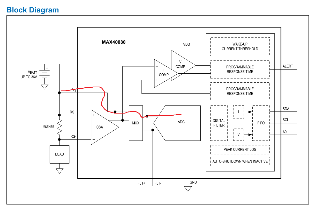
But datasheet mention another important parameter – “Voltage buffer gain” as a 1/30:

image

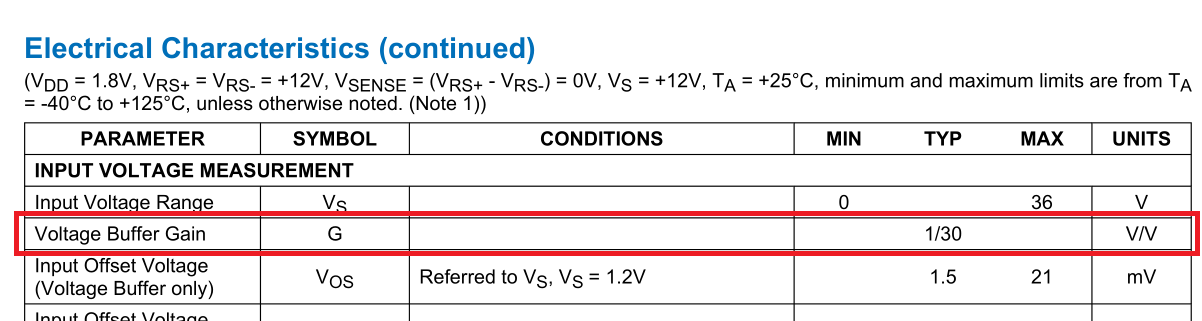
So, input voltage is divided by 30 before applying to ADC which has reference of 1.25V:

image

ADC provides maximum range of voltage measurements is 30 * 1.25V = 37.5V. Now you can compute value of 1 LSB of over and under voltage detection just by dividing this limit by 64: 37.5V / 64 = 0.586V. This is resolution of over and under-voltage detection on MAX40080. For test I did experiment.

Experimentally detecting overvoltage detection level

Instead of any power supply I connected DAC (Digital to analog converter) to the VIN pin of Current 6 Mikro E Click Board. I used MAX5715 DAC on breakout and connected it in the following way:

image

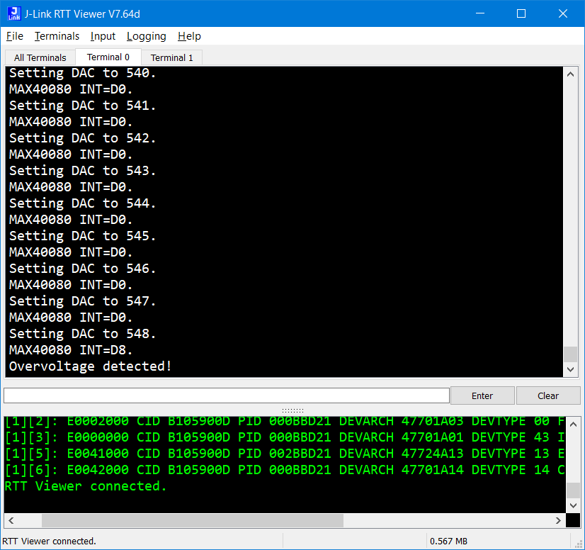
In firmware of MCU I configured MAX40080 over-voltage detection to just one. After configuring it, I started increasing voltage of DAC (with reference of 4.096V). After every increment I checked overvoltage interrupt flag in MAX40080 Interrupts register.

Overvoltage occurred on value 548 which with 4.096V reference of 12-bit DAC means 4.096 * 548  / 4096 = 0.548V which is very near estimated value 0.586V which we deduced form datasheet. Accuracy of overvoltage detections seams to be 38 mV at this level under these conditions.

image

Closing

Thank you for reading this blog post. I wrote them in a hurry before contest deadline. I of course did not plan to write this blog post, but I hope it may be helpful for other challengers who wanted to use over-voltage (or other over/under detection) of MAX40080 chip. In next few minutes I will post my final summary blog.

Next blog: Misaz’s Experimenting with Current Sense Amplifiers Summary Blog

  • Sign in to reply
  • misaz
    misaz over 3 years ago in reply to aspork42

    Have you enabled storing voltage to the FIFO in FIFO Config Register? When sensor is configured to sample only current (default configuration), then under and overvoltage detection don’t work. In this mini-experiment I configured sensor by following parameters:

    • Mode of operation: active
    • Sample rate: 1Msps (I did not connect any samples in this experiment. So, FIFO overflown quickly, but I was interested only in interrupt flags in this experiment)
    • Storing voltage only in the FIFO (If you choose storing both voltage and current, then remember to set sample rate to 0.5 ksps)
    • I configured enabled interrupts (interrupt sources that asserts IO pin) to overvoltage only (FIFO overflow for example did not assert interrupt signal, but flag in register was of course set as you can see from screenshot)
    • Other parameters at default values

    Also note that on MikroE Click Board interrupt signal is inverted by transistor (which also act as level shifter), so interrupt is efficiently active high instead of active low. I recommend filtering interrupt sources which triggers this signal in INT_EN register. Especially interrupts from FIFO are annoying unless you really need them.

    While block diagram show voltage detections implemented using (analog) comparators, I think they are internally implemented as digital comparisons. I think it because there is configurable Alert response time:
    image

    And electrical characteristics contains mentioned latencies of this detection at different sample rates and configurations:

    image

    Block diagram of device is little bit misleading here, because visualize detections as independent on ADC while they are dependent at least on ADC sample rate.

    • Cancel
    • Vote Up 0 Vote Down
    • Sign in to reply
    • More
    • Cancel
  • aspork42
    aspork42 over 3 years ago

    This is a nice closed-loop test. I need to play with me sensor some more and simplify code to see if I can get similar results. I was setting the alert level then running the power supply up and down but could never get the alerts.

    • Cancel
    • Vote Up 0 Vote Down
    • Sign in to reply
    • More
    • Cancel
element14 Community

element14 is the first online community specifically for engineers. Connect with your peers and get expert answers to your questions.

  • Members
  • Learn
  • Technologies
  • Challenges & Projects
  • Products
  • Store
  • About Us
  • Feedback & Support
  • FAQs
  • Terms of Use
  • Privacy Policy
  • Legal and Copyright Notices
  • Sitemap
  • Cookies

An Avnet Company © 2025 Premier Farnell Limited. All Rights Reserved.

Premier Farnell Ltd, registered in England and Wales (no 00876412), registered office: Farnell House, Forge Lane, Leeds LS12 2NE.

ICP 备案号 10220084.

Follow element14

  • X
  • Facebook
  • linkedin
  • YouTube