


I welcome you to my second blog about my experiments as part of Experimenting with Current Sense Amplifiers Design Challenge. In previous blog post I introduced my experiment plans as part of this Design Challenge. Today I will show my first experiments with MAX40080 Current Sense Amplifier sensor. This blog post can be partially considered as mini tutorial showing basic usage of MAX40080 CSA sensor and related Current 6 Click board with Raspberry Pi. In this blog I will use Python for small programs. The goal of this initial experiment is to measure current flowing through resistor to check that sensor works correctly.
Connecting Pi 3 click shield
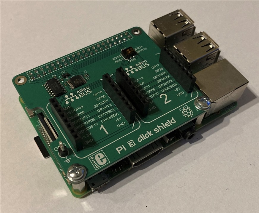
The first step is to connect Pi 3 click shied to the Raspberry Pi. This is easy step. You just need to plug shield on Raspberry Pi and optionally use standoffs to make connection more robust. Pi 3 click shied which I have received for free from Element14 as part of this design challenge contains two standoffs, so I used them, but 2x20 connector is strong even without them. Connection should look like this:
Connecting wires to Current 6 Click Board
Current 6 click board which is main component of this design challenge has four terminal block inputs. You need the small screwdriver. This was my first issue which I have experienced in this contest  I did not find any so small screwdriver in my toolbox. I measured it and screw hole diameter is less than 2mm. I considered ordering compatible screwdriver and waiting for it but after some time I decided to try do it in DIY way and after some experiments I was able to screw it using manicure scissors. I never realized how much time it can take to connect four wires to terminal block . So finally, I connected them:

Connecting testing circuit
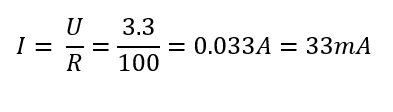
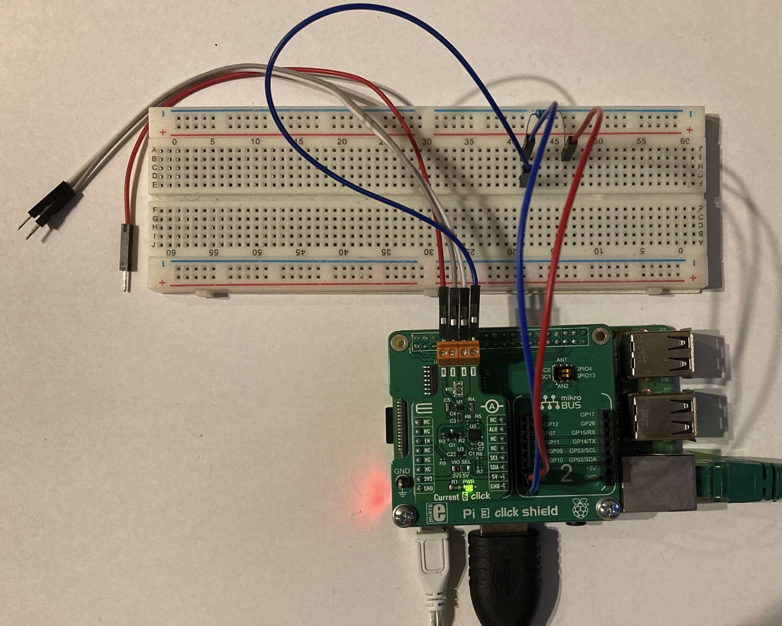
The next step is preparing testing circuit. As I stated in this initial experiment, I will measure current flowing by simple resistor. Because native GPIO pins are occupied by Pi 3 Click Shield, you cannot use them directly but both GND and 3.3V are available at both mikro BUS connectors, so you can connect your circuit to them. The important note is that current sourced by 3.3V pin of Raspberry Pi GPIO should be less than 50 mA and this includes also power consumption of our MAX40080 sensor (which is in fact very low, so we do not need to worry about it much). But it is very important when selecting resistor value. For first demonstration I will use 100 ohms. According to ohm law the current flowing by resistor would be 33mA which fits the 50mA limit.
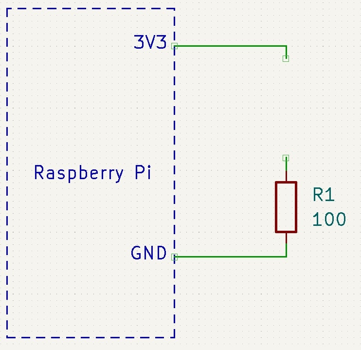
Schematically connection looks like this:

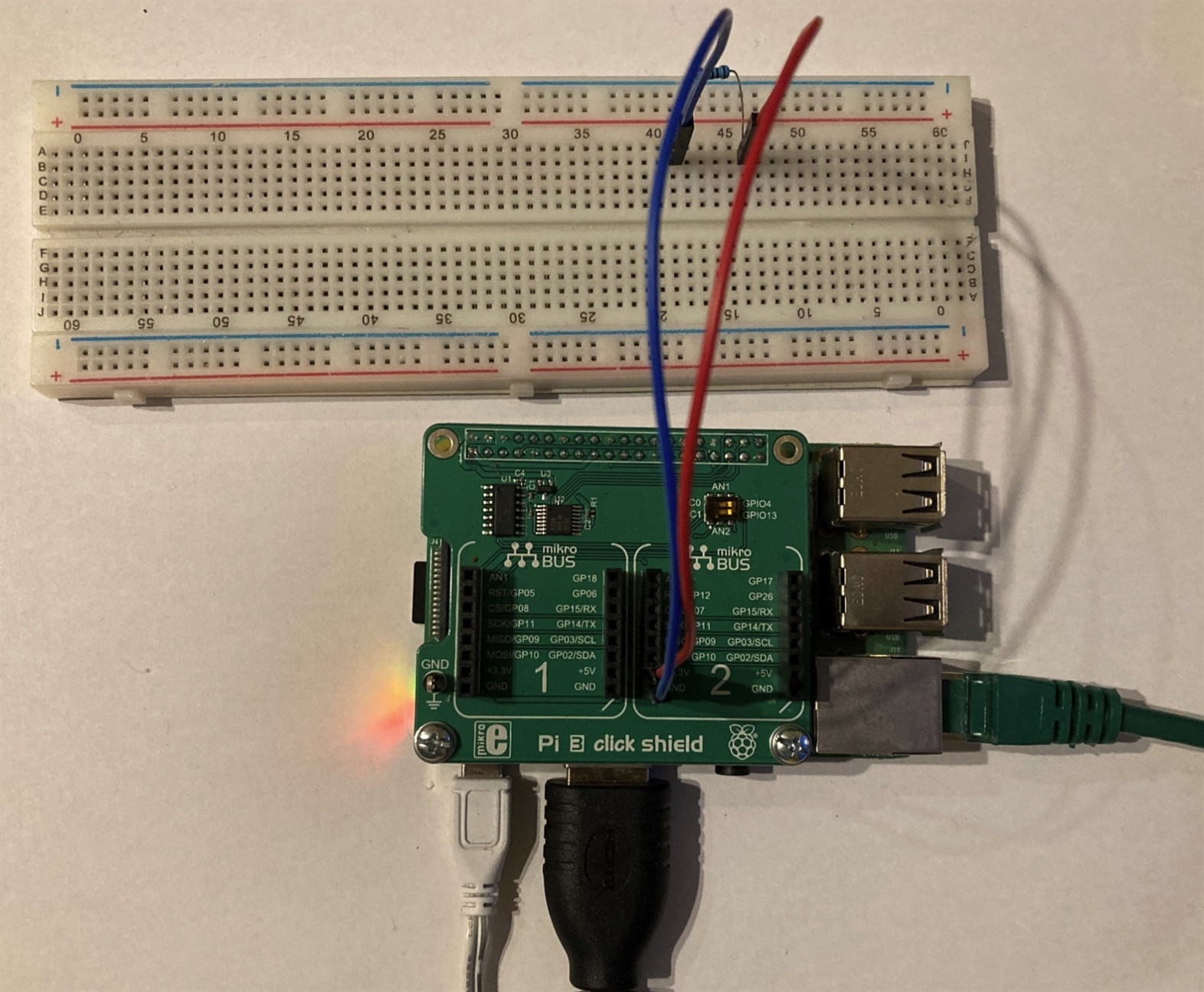
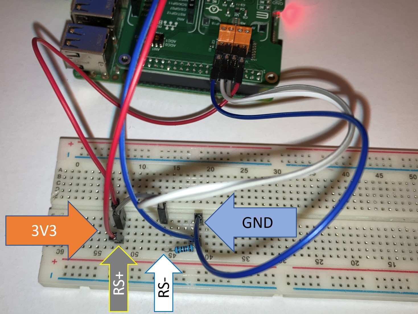
And finally in real world, it looks like this:
Connecting Current 6 Click
Now you can connect Current 6 Click board to the Pi 3 click shield.
The (important) first step is connecting GND wire to GND of measured circuit. In my case it is blue wire. In this case in fact, it can be omitted because ground of the tested circuit and sensor is the same ground. But for showing best practises I will still connect it:
The second optional step is connecting red wire to the power supply voltage of the measured circuit. For measuring current it is not mandatory, but MAX40080 can also measure voltage (up to 36V) so we can connect this to the other side of resistor.
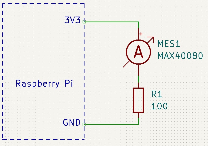
The next step is connecting sensor to the circuit for measuring current. Like standard amperemeter we need to disconnect the circuit at some point. Later we will connect remaining two wires to the newly created gap. Schematically we will do following:
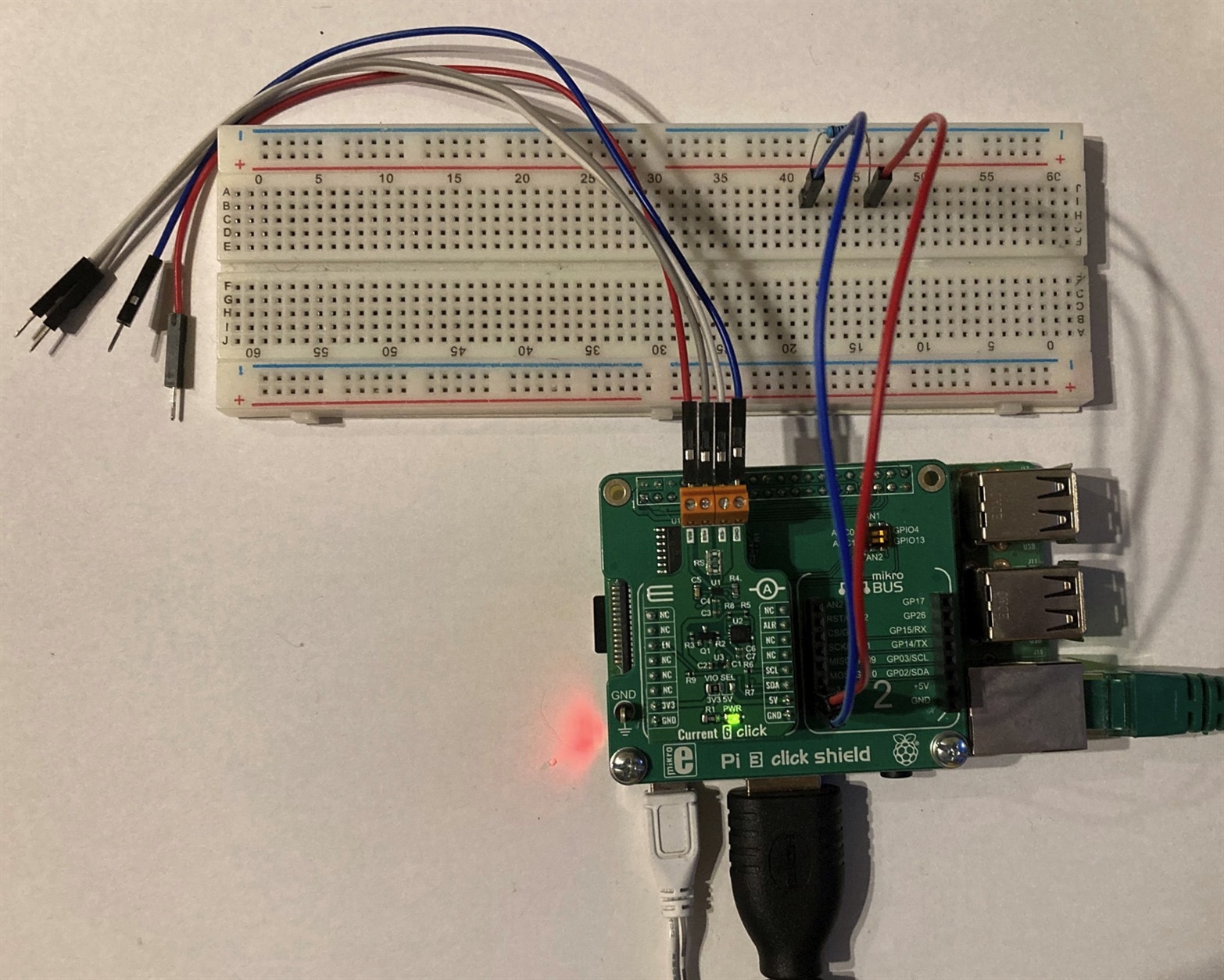
And in real world:
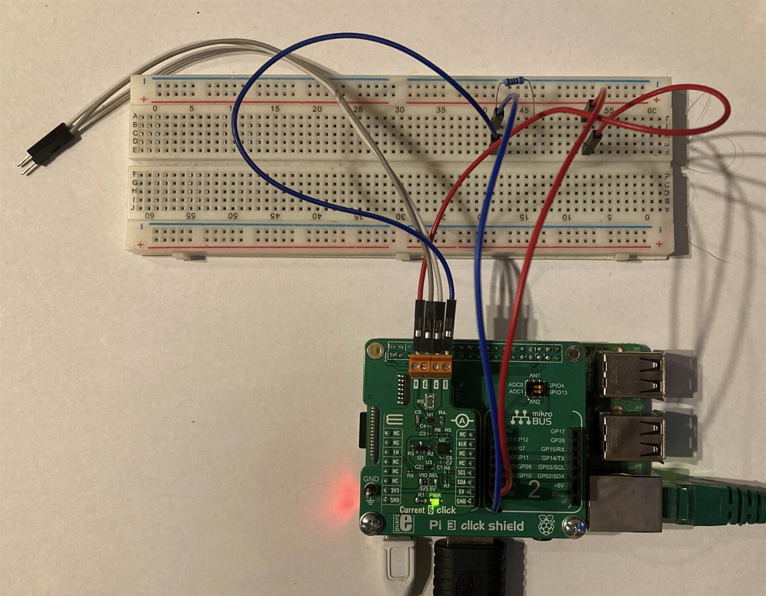
The final step is connecting the amperemeter (which is MAX40080 sensor in our case) to the newly created gap in our circuit. Sensor has two wires (white and grey in my case) named RS+ and RS-. Usually, you connect RS+ to higher voltage which is near red wire in my case and RS- to the direction of lower voltage which is near resistor in my case. But sensor is bi-directional so you can safely reverse the connection. Only difference will be that you will read negative values from the sensor later. Schematically we will do following:
And in real world:
And that’s it. Now we can setup software and make current measurements.
I2C Scan
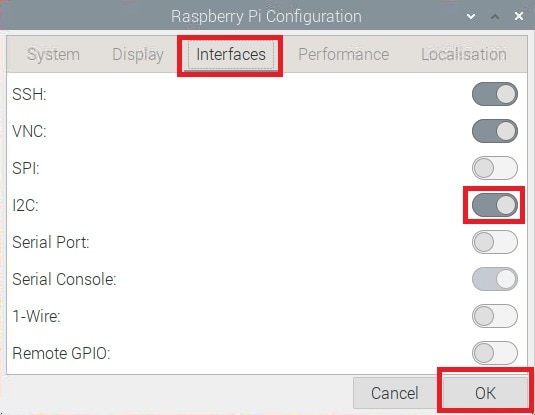
MAX40080 is I2C sensor. Raspberry Pi and Linux operating system supports this bus and have implemented drivers for it, but you need to enable the driver.
In Raspberry Pi OS (formally Raspbian) go to menu > Preferences > Raspberry Pi Configuration. Then go to Interfaces tab, enable I2C and confirm dialog:
At this point I opened terminal and run i2cdetect command.

Unluckily the command did not find any device on the bus. As a little bit experienced user of I2C devices, I know that system may have more than one I2C controller so I also tried listing the I2C controllers and running i2cdetect against the second controller:

The command found some devices but which one of them the MAX40080 is?
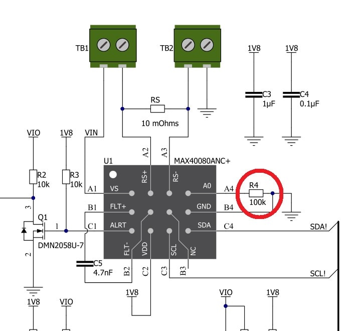
According to MAX40080 datasheet, I2C address is determined by resistor connected to A0 pin. Because we are using Current 6 Click board, we can find this value in schematic of click board. It is 100kOhm:
According to datasheet device address is 010001:
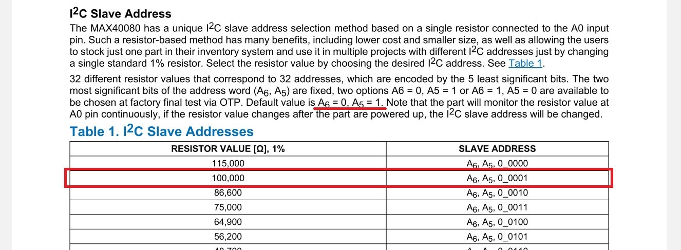
Address 010001 is 0x21 hex but wait... Previous i2cdetect did not detect any device at address 0x21. So, what is wrong? Click board LED lit so the board is properly powered. I double checked that it is correctly fitted in the shield. Even more I used logic analyser and I have really seen that device do not answer the request at address 0x21 (when using logic analyser, I also ensured that correct I2C driver for bus exposed on GPIOs is the first one).
20 minutes later…
After some analysis I found that there are no voltages on components near MAX40080 sensor. The board has onboard LDO converting input voltage 3.3 V or 5 V to the 1.8V which is required for MAX40080 operation and this LDO did not provide any power to the sensor. After investigation schematic I found that LDO used for powering MAX40080 have ENABLE pin and this pin is not connected to the power or GND rail by pull up/down resistor, but rather is exposed to the GPIO pin of the Click board:

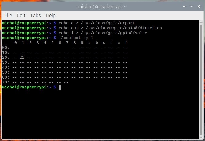
By default, Raspberry Pi GPIO is in high impedance state, so I measured voltage about 0.5V on enable pin which means that LDO is disabled. For fixing the issue I configured Raspberry Pi GPIO pin to output and set its value to logical one. You can do this from the terminal using following commands. They work when click board is placed in first click slot. If you are using it in second slot, replace value 8 by 7 in first command and gpio8 by gpio7 in second and third command.
echo 8 > /sys/class/gpio/export
echo out > /sys/class/gpio/gpio8/direction
echo 1 > /sys/class/gpio/gpio8/value
After running this, I was able to successfully detect MAX40080 on the bus:
Installing python libraries
As I stated at the beginning, I will use Python for this experiment. Python is installed on the Raspberry Pi by default but libraries which I will use are not. Install them using following command:
pip3 install smbus matplotlib
Reading MAX40080 registers
The first example is very simple. I will read configuration register and current measurement register. They are at addresses 0 and 12 (0xC in hex) according to datasheet:

Code is very simple. It initialize SMBus driver which is used for driving I2C bus and read block data. Both values are 2 bytes wide but reply from MAX40080 also contains third CRC byte, so I will read 3 bytes. Then I will print them.
import smbus
import matplotlib.pyplot as plt

max40080_addr = 0x21

bus = smbus.SMBus(1) # Use /dev/i2c-1

# check configuration
value = bus.read_i2c_block_data(max40080_addr, 0x00, 3)
print("cfg reg =", value)

# read measurement
value = bus.read_i2c_block_data(max40080_addr, 0x0C, 3)
print("data reg =", value)
Output is following:

This is valid output. We can see that CRC byte is set to some value which looks like valid CRC at the first look . The value of configuration register is also valid. From the datasheet we know that value should be 0x0060 and 0x60 is 96 in decimal. Data which we received are empty and invalid (15th VALID bit is not set). It is because sensor is by default in standby mode and not do any measurement.
Configuring MAX40080
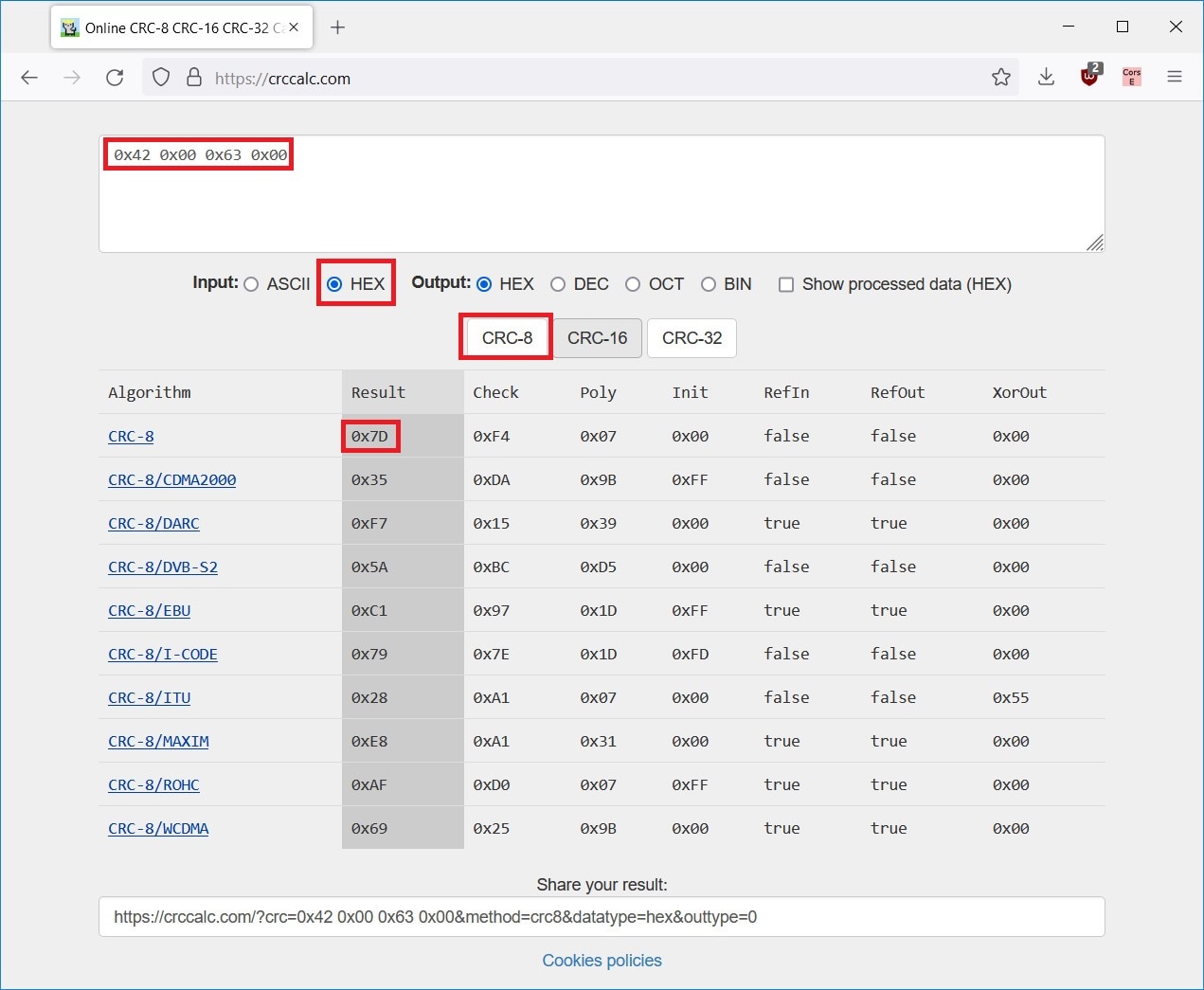
The next step is configuring MAX40080 to do any measurements. We will remain PEC (CRC) enabled and voltage range at default value and change mode from standby to the active mode. The new value will be 0x0063. Note that values transmitted to and from the sensor are little endian. Last step is to calculate CRC for our command. For now, I used online calculator. CRC message must be calculated from all bytes of the message including address byte with direction bit. So, we will compute CRC of bytes 0x42 (device address + write direction), 0x00 (register address), 0x63 (LSB of register value), 0x00 (MSB of register value). Result is 0x7D:
I also added some delay to allow MAX40080 taking measurement before reading it (immediate reading caused still receiving zeroes). Following lines were added to the code
import time

# set mode from standby to active
bus.write_i2c_block_data(max40080_addr, 0x00, [0x63, 0x00, 0x7D])

# wait for first measurement
time.sleep(0.1)
Output will be following:
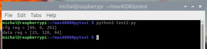
We can see updated configuration (99 is 0x63 hex) and we can also see measurement. Second byte tells us that VALID bit is set, other bits are zeroes and lower bits are 21 dec, so we measured value +21.
Parsing values and plotting chart
Final program upgrade as part of this blog post is that I extend script with loop collecting 100 samples and then I will plot them using matplotlib library. For doing this I need to parse value from bytes which I have received. According to datasheet, structure of the register is following:

I need to filter out VALID bit and do sign extension to fill gap created by filtering VALID bit. Following code replaces main part of script. The main part of the code is in the middle. The first three lines are simple Python code which creates array, loops 100 times and reads data from sensor which we have already seen. The next line is responsible for filtering VALID bit (this is done by mask 0x7F which is in binary 0111_1111). MSB after flag filtering is shifted 8 bits left and it is ORed with unmodified LSB. The second line do sign extension. Sign is 14th bit in the number (counted from 0). This bit is selected by mask 0x4000 (0100_0000_0000_0000 in binary) and then is shifted right to the latest 15th bit. Next, the value is ORed with remaining unchanged bits of number. Third line converts number back to bytes and fourth line use python function to convert 2 bytes to signed integer (original number was interpreted as unsigned number). Finally, value is appended to the array and there is some delay before collecting next sample.
measurements = []
for i in range(100):
    value = bus.read_i2c_block_data(max40080_addr, 0x0C, 3)

    filtered_flag = ((value[1] & 0x7F) << 8) | value[0]
    sign_ext = ((filtered_flag & 0x4000) << 1) | filtered_flag
    bytes_after = [sign_ext & 0xFF, (sign_ext & 0xFF00) >> 8]
    measured_value = int.from_bytes(bytes_after, "little", signed="True")

    measurements.append(measured_value)
    time.sleep(0.001)
At last I plot the chart:
print("Average:", sum(measurements) / len(measurements))
plt.plot(measurements)
plt.ylim(ymin=0)
plt.show()
Output is following:
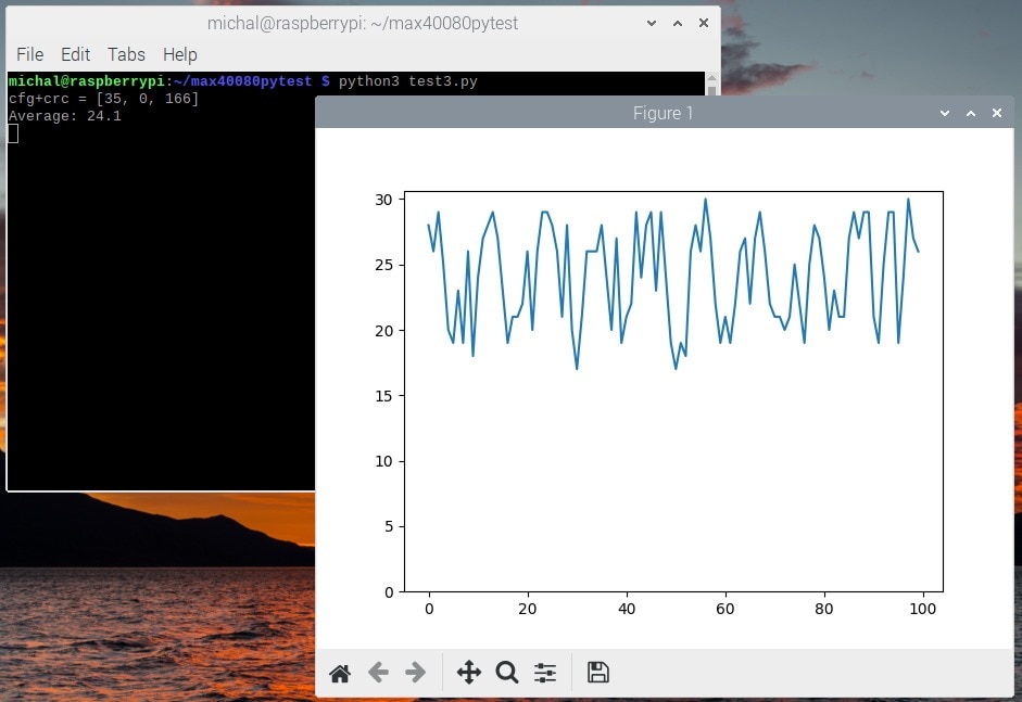
We can see that we received small values between 18 to 30. They are correct. Currently we sense very small current (about 33mA). Also note that values are not in Ampere units. It is raw value received from sensor in range -4095 to 4095. How to convert this measured value to current in Amperes I will show in next blog post.
Swapping RS+ and RS-
The last experiment which I will do as part of this blog post is that I will try swap RS wires and we should see similar values (between about 20 to 30) but negative. Only change in code is that we need to remove setting plot Y axis starting at zero (now it needs to start at negative values). We need to remove following line:
plt.ylim(ymin=0)
After that, the output will be following:
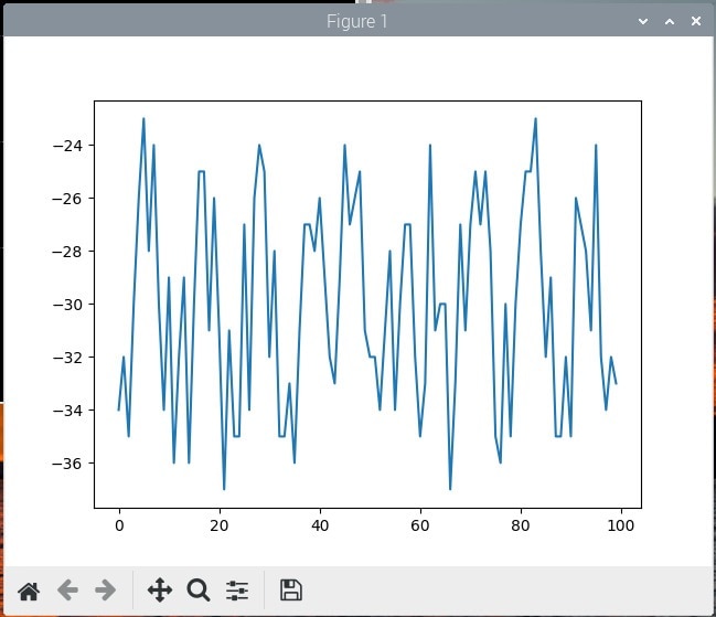
So finally, we can see that sensor is working correctly (and my Python code handle negative numbers correctly). We received values about -30 which is similar what we have seen in previous (positive) case. In both cases we have seen some noise which most probably comes from my DIY breadboard setup. Sensor measures very low voltages in range +- 50mV and measured value -30 corresponds to only -0.00037 volts! So, it makes sense that that this circuit is sensitive to noise. Spoiler from next blog post is that values about 27 are valid and corresponds to theoretical 33mA which we expect on 100 ohm resistor powered by 3.3V.
Summary
In this blog post I shown my first experiments with MAX40080 CSA. I described some issues which I have faced and may be helpful for other challengers. Then I shown simple Python programs for reading and configuring MAX40080 and finally I shown some plots of measurements.
Future plans
In next (3rd) blog post I will describe how to precisely convert measured value to Amperes. This is important when working with CSA, but it is not as easy as it could look at the first look. I will show both experimental and precise approaches. Then I plan to do some experiments with the same setup as you have seen in this blog post. Today I used only small currents (33mA), small voltage (3.3V) and only most simple configuration with almost all interesting MAX40080 features disabled. So, in 4th blog post I will do more experiments with this setup, and I will more deeply evaluate MAX40080 CSA. As I stated in my Introductory blog post I will create my own library for using this sensor with microcontrollers. This library I will most probably show in 5th blog post. I am working on it at the time of writing this blog post. For some further experiments I need PCBs which I already ordered at OSH park, and I expect them in about month. I also need to buy some components. In meantime I plan to start making some project mentioned in first post which do not rely on PCBs like long-term power consumption monitoring.
For this blog post its totally all. Thank you for reading it and stay tuned. I also like to hear any feedback in comments.
Top Comments
-

guillengap
-
Cancel
-
Vote Up
0
Vote Down
-
-
Sign in to reply
-
More
-
Cancel
-

misaz
in reply to guillengap
-
Cancel
-
Vote Up
0
Vote Down
-
-
Sign in to reply
-
More
-
Cancel
-

guillengap
in reply to misaz
-
Cancel
-
Vote Up
0
Vote Down
-
-
Sign in to reply
-
More
-
Cancel
-

misaz
in reply to guillengap
-
Cancel
-
Vote Up
0
Vote Down
-
-
Sign in to reply
-
More
-
Cancel
Comment-

misaz
in reply to guillengap
-
Cancel
-
Vote Up
0
Vote Down
-
-
Sign in to reply
-
More
-
Cancel
Children