


I welcome you to my next blog post as part of Experimenting with Current Sense Amplifiers Design Challenge. In my first blog I described my experiments plan and in my second blog post I shown basics of using MAX40080 sensor as part of MikroE Current 6 Click Board. In this third blog I will continue with fundamentals of MAX40080 sensor. In this blog post I will describe approaches how to find formula for converting measured digital value in range between -4095 and 4095 to real value in Ampere unit. I will show two approaches how to do this. The first I will show experimental approach of determining formula from measured values at known currents and then I will show accurate approach providing exact formula for converting value.
Experimental approach
The first approach which I will describe is experimental. If we do not know how to convert measured value exactly, we can suppose some things and then estimate function (for example linear function) that we can use for converting value. In case of current sensing, we luckily can suppose linearity of value because we measure voltage drop on shunt resistor which is linear with current according to ohm law and ADC inside MAX40080 is also almost linear. Se we can set up two experiments with two different static known currents flowing through circuit, read values measured by sensor and compute coefficients of linear function using linear interpolation. So, lets experiment.
For the first measurement we can reuse values measured from previous blog. In this blog I used 100ohm resistor powered by 3.3V rail of Raspberry Pi and sensor returned values between around 20 to 30 and we computed average of 100 samples as a 24.1. So, for first measurement of theoretical current 0.033 A (value 0.0333 is computed using ohm law as a U / R where U is voltage on resistor 3.3V and R is value of the resistor) we know that sensor returns 24.1.
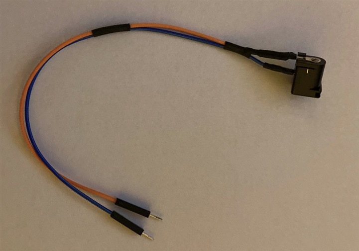
For second measurement I upgraded my setup. Because I have no regulable high power bench power supply, I was limited to standard power adapters. Instead of 3.3V from Raspberry Pi which is limited to source 50mA I decided to use 12V from barrel jack. I bought barrel jack connector and solder wires to it:
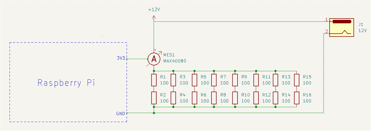
For powering I used old router power supply which can source 5A/12V. The next material issue which I faced was resistor. At this point I realised that is easy to make some high current flow like 1A, but do I have resistor which can handle this current without overheating? I don’t. All my resistors which I have can handle 0.25 or 0.6W, but for handling so “high” current (about 1 Amp) on “high” voltage (about 12 V) requires 12 Wats (P = U * I = 12 * 1 = 12). After some calculations and estimation, I decided to make setup of 16 × 100-ohm resistors connected using 8 paralell branches and each branch having 2 resistors connected in series. This result to final resistance of 25 ohms (100 * 2 / 8), allowing to flow 0.48 A at 12 V and reducing load on each resistor to 0.36 W (limit is 0.25 but this I did not considered as significant violation at room temperature). Final connection looks schematically as follows:
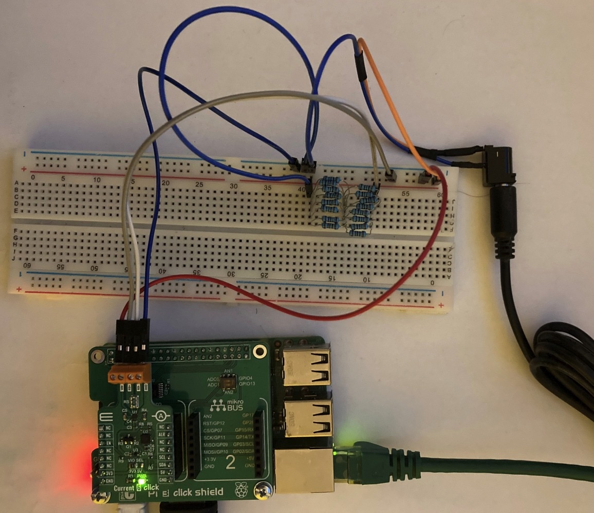
And in reality:
After connecting I run the same program as in previous blog post with following output:

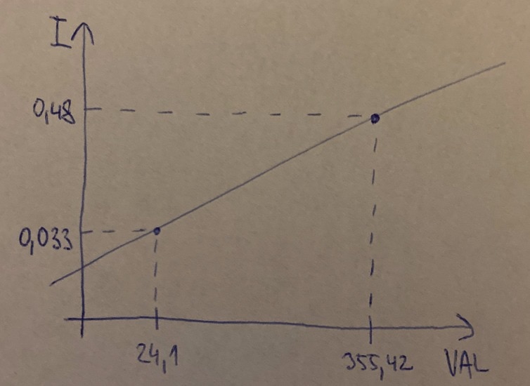
Now we get higher numbers than in previous case and it is expected behaviour because we measure higher current. So, we have two measurements of two different currents 0.033A and 0.48A and two different values 24.1 and 355.42 calculated based on data from sensor.
Experimentally determining conversion formula using linear interpolation
Now we know two inputs and corresponding outputs of some linear function. I will refer value returned by sensor as VAL and real current as I. Linear function and our known points looks on the plot as follows:
Generic formula of linear function looks as follows:
![]()
And if we replace X and Y by our variables:
![]()
So, it is function which expects VAL as parameter and outputs real current as a value. Our task is to find parameters A and B which are used within formula. The purpose of linear interpolation is to build two equations (with two unknown variables A and B) and solve it. We replace VAL by known values returned by sensor and I by theoretically known corresponding currents. The equations look as follows:

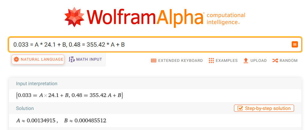
And now we can solve them. You can use online solver like WolframAlpha, but I did it manually using multiplication of first equation by constant and then summing with second equation. After it one unknown variable disappear (it is multiplicated by zero) and after that we can get value of one coefficient by solving simple single equation containing single unknown variable:
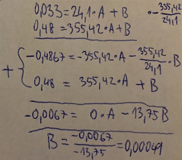
And now we can place newly discovered value of B param to one of original equation and simply solve it:

Now we know A and B params. I used WolframAlpha for checking my results. Computed parameters look correct and rounding errors which I did does not look significant:
So, now we can place parameters A and B to original formula and get resulting linear function for converting measured value to real current in Amperes:
![]()
Testing Formula
For testing formula, I used another third configuration with resistor. I used 12V as in previous case and 220ohm resistor (in fact it was 2 × 2 series-parallel configuration). Expected current from ohm law is 12 / 220 which is approximately 55mA. So, lets check. I used the same program with following output:
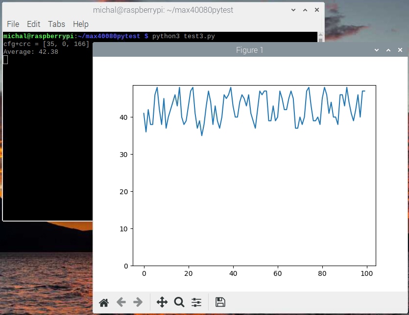
So now we can “call” our function F with value 42.38 and see what we get:

We got 0.0577 A which is after converting from A to mA 57.7mA and this is very near our known theoretical result 55mA. It looks that our experimentally determined formula is correct. Minor error is caused by noise, accuracy of voltage and resistor values used and so on. Our formula is not totally correct because we computed it from similarly inaccurate values.
Only single sample suffice
One possible upgrade of our formula reduces need of parameter B with another small assumption. We can assume that sensor returns 0 when measuring 0A current and then we need only one point. This assumption is quite trivial. Efficiently we reduce equations by B parameter which would be zero. Note that we calculated B parameter near zero. The non-zero B parameter introduce some offset to our calculations, and it is problematic especially when measuring negative values.
Accurate Approach
In previous section you have seen experimental approach of estimating coefficients for converting measured value to current. But MAX40080 is not a black magic, and all its structures are documented. We can make exact formula using parameters from datasheet. I will describe process in a reverse way: from 12-bit digital value to real current. The important image for this section is block diagram of MAX40080 sensor from datasheet:
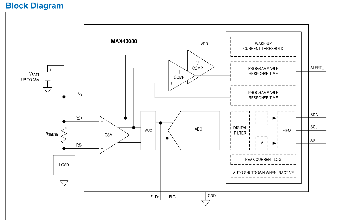
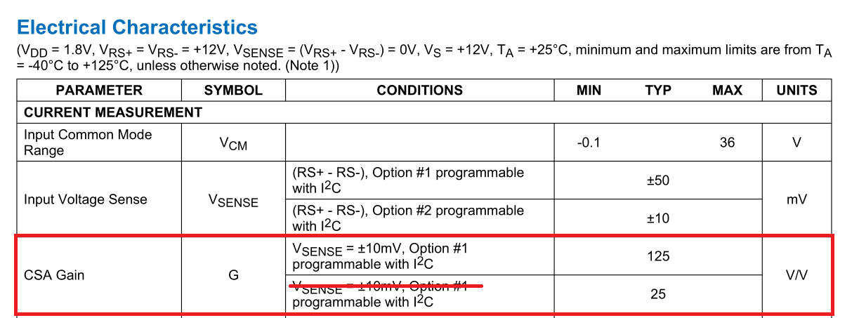
The first step of making formula is realize what does the senser measure. The digital value which we receive comes from ADC. ADC in MAX40080 is 12-bit, so it converts voltage in range 0V to reference voltage and convers it to value between 0 to 4095 (2^12 – 1). MAX40080 is bidirectional so it adds 13th bit and returns value in range -4095 to 4095. The first question is what the reference voltage is? The answer is in datasheet: It is 1.25V:

So MAX40080’s ADC converts value in range -1.25V to 1.25V (I personally thing that it internally measures voltage in range 0 to 1.25V and sign bit is provided by some comparator externally. It is internal detail, and I did not find accurate answer to this question in datasheet but it is not important for us).
From this knowledge we can convert digital value to voltage (still not a current) by simple cross multiplication (or linear interpolation with single point as used in previous sections):

Now we received voltage on input of ADC. Input of ADC is connected across some multiplexer and filtering circuit from amplifier. This amplifier has fixed gain 25 or 125 depending on configuration. Note that datasheet has wrong label which I crossed out for making it less confusing.
So, if we want to get voltage on input rather the amplified one, we just need to do reverse operation of amplification which is division. Formula will look as follows:
So now we have computed real voltage on the input of MAX40080 chip but we do not need a voltage. We rather need the current. So now we must understand what we are really measuring. The answer is also visualized on block diagram from MAX40080 datasheet:

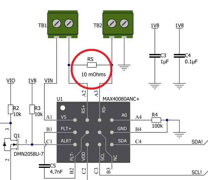
So, we are measuring voltage drop on resistor which is outside the MAX40080. In our case it is resistor on MikroE Click Board. It is this resistor:
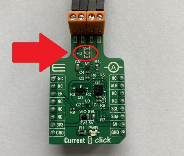
It is large because it can handle large current. In opposition its value is very small because it should be transparent for measured circuit. Its value is only 10mOhms (mili-ohms) according to datasheet:
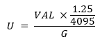
So now we know formula for getting measured voltage, we know value of resistor having measured voltage drop so now we can use simple ohm law to get final formula for getting value of current from measured value:
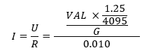
We can simplify nested fractions:
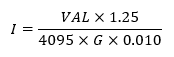
And this is final formula which we can use for converting measured value (VAL) to current I in Amperes.
Testing Formula
Our script used standard 50mV range, so G value is 25. We can try evaluating our formula for measured values from my previous experiments. We know that sensor returned values around 355.42 (which was average for 100 samples) for theoretically computed current of 0.48A. So, let’s check formula:
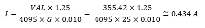
We are near expected result. In this case error is not caused by an experimentally determined coefficients, but rather by noise, and also improper calculation of theoretical currents resulting from assumed voltage exactly 12V and resistor value exactly 25ohm which both was inaccurate with some tolerance in real world.
Comparing Experimental and Theoretical Results
Finally, we can compare our theoretical formula with experimentally deduced one. Theoretical formula matches our assumption that B param should be zero. When you measure value of 0, you get 0A of current. Now think about A param. A param is coefficient which corresponds to value in Amperes for one measured unit. So, if we evaluate our exact formula with VAL=1, then we should get A param of our experimentally deduced formula. Let’s do this:
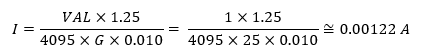
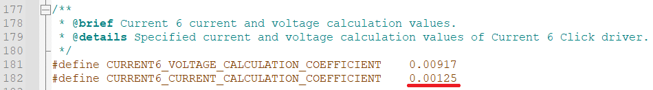
Our experimentally estimated coefficient was 0.00135. 0.00122 and 0.00135 are very similar numbers which confirms that both methods resulted into very similar formula. Lastly, we can compare with results coming from somebody else. If you download official library from MikroE and opens current6.h file, you can see that this library use coefficient of value 0.00125 which is also very similar to coefficients computed by me:
Summary
In this blog post you have seen two ways how to get or compute formula for converting measured value from MAX40080 CSA sensor to value in real Ampere unit. I shown experimental way gathering formula from measurements using linear interpolation and also you have seen accurate method providing formula from datasheet parameters. From practical point of view, these information are useless because we can just use formula and coefficients computed by someone else. But I still like it. I learn a lot. This process allowed me to deeply understand operation of MAX40080 CSA and CSAs in general. In fact, this process is very similar for other CSA no matter of vendor. Only parameters like G, and Vref differs. Sometimes internal structure differs slightly.
Experiments Status and Future Plans
At the time of writing this blog post I started experimenting with using MAX40080 from MAX32625 microcontroller. After first MCU experiments I faced some issues that cost me a lot of time and I also found some mistakes in datasheet which I will report to Maxim. I am currently testing my own library and I plan to post some first thoughts soon. I also plan to prepare some simple Python library because I feel some interest from other challengers due to lack of any official library for Raspberry Pi. I also have some idea how to utilize my library for MCUs on Raspberry Pi and I am considering creating CLI utility for interacting MAX40080 without any programming needed. I am still waiting for PCBs for my more advanced experiments. OSHPark panelised them and send them to fab but still did not ship them to me. In the meantime, I ordered and received required components.
Last Words
For this blog it is totally all. Thank you for reading it and stay tuned. If you find any inconvenience or other issue in my formulas, computation or somewhere else, feel free to write a comment. I also like to hear any feedback in comments.
Next blog: Blog #4: Using MAX40080 CSA with MAX32625 MCU – First thoughts
-

guillengap
-
Cancel
-
Vote Up
0
Vote Down
-
-
Sign in to reply
-
More
-
Cancel
-

misaz
in reply to guillengap
-
Cancel
-
Vote Up
0
Vote Down
-
-
Sign in to reply
-
More
-
Cancel
-

guillengap
in reply to misaz
-
Cancel
-
Vote Up
0
Vote Down
-
-
Sign in to reply
-
More
-
Cancel
-

misaz
in reply to guillengap
-
Cancel
-
Vote Up
0
Vote Down
-
-
Sign in to reply
-
More
-
Cancel
Comment-

misaz
in reply to guillengap
-
Cancel
-
Vote Up
0
Vote Down
-
-
Sign in to reply
-
More
-
Cancel
Children