


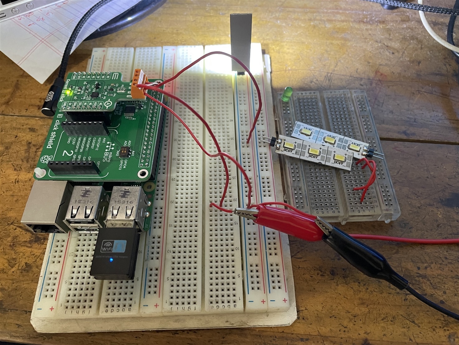
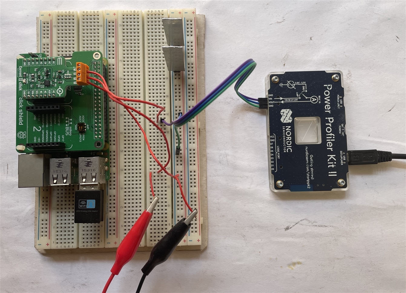
 In this blog post, I will change different parameters like the sample rate, and digital filter of the current sense amplifier and try to find if there is any effect of those parameters on accuracy and stability. For this purpose, I will measure the current passing through a small LED panel from a 4V supply. I will change the power rating of the load but throughout my experiment, I will not change the supply voltage. The following image shows the circuit setup. I will plot a graph for every test using 1000 sample measurements.
Effect of using the internal digital filter
The digital filter provides the opportunity to calculate the average among multiple samples. It number of samples for averaging can be set for 1, 8, 16, 32, 64, and 128. The following table is populated using the test data by applying different filter options:
| Sl No | Voltage (V) | Power (W) | Samples | Average Current (mA) | Graph |
| 1 | 4 | 1.2 | 1 | 268.69 | Fig.1 |
| 2 | 8 | 270.92 | Fig.2 | ||
| 3 | 16 | 248.55 | Fig.3 | ||
| 4 | 32 | 267.52 | Fig.4 | ||
| 5 | 64 | 268.60 | Fig.5 | ||
| 6 | 128 | 269.77 | Fig.6 |
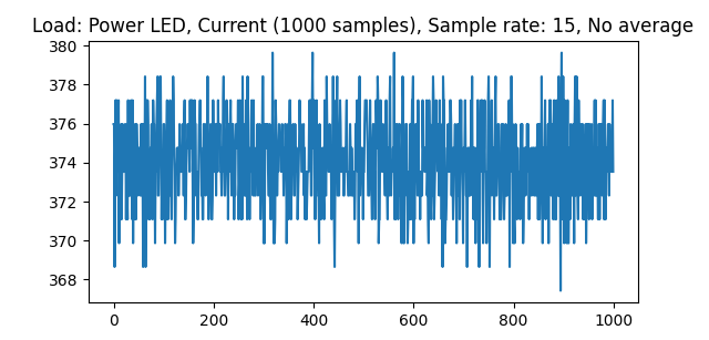
Fig.1
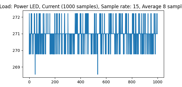
Fig.2
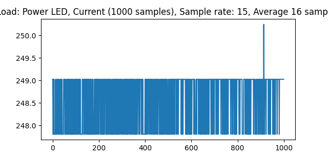
Fig.3

Fig.4
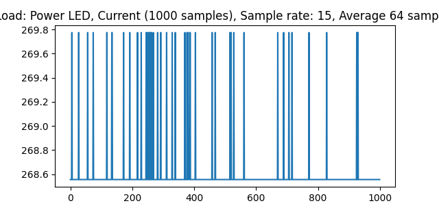
Fig.5
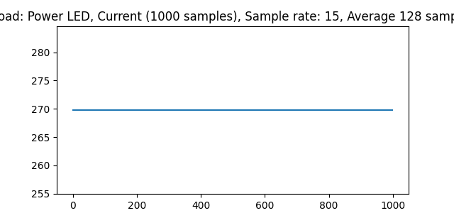
Fig.6
From the above experiment, it seems accuracy does not be affected by the digital filter. It takes a little bit more time to show the result for a higher filter rate but for a higher filter we can get a more stable output. It may be useful where manual averaging is not possible.
Effect of changing sample rate
From the same circuit setup following data was generated by changing the sample rate without applying any internal digital filter:
| Sl No | Voltage (V) | Power (W) | Sample Rate (ksps) | Average Current (mA) | Graph |
| 1 | 4 | 1.2 | 15 | 268.56 | Fig.7 |
| 2 | 18.75 | 236.88 | Fig.8 | ||
| 3 | 23.45 | 236.19 | Fig.9 | ||
| 4 | 30 | 248.38 | Fig.10 | ||
| 5 | 37.5 | 250.25 | Fig.11 | ||
| 6 | 47.1 | 246.20 | Fig.12 | ||
| 7 | 60 | 246.11 | Fig.13 | ||
| 8 | 93.5 | 236.50 | Fig.14 | ||
| 9 | 120 | 233.10 | Fig.15 | ||
| 10 | 150 | 239.62 | Fig.16 | ||
| 11 | 375 | 236.51 | Fig.17 | ||
| 12 | 750 | 238.18 | Fig.18 | ||
| 13 | 1000 | 242.94 | Fig.19 |
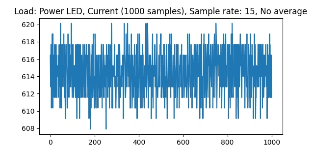
Fig.7
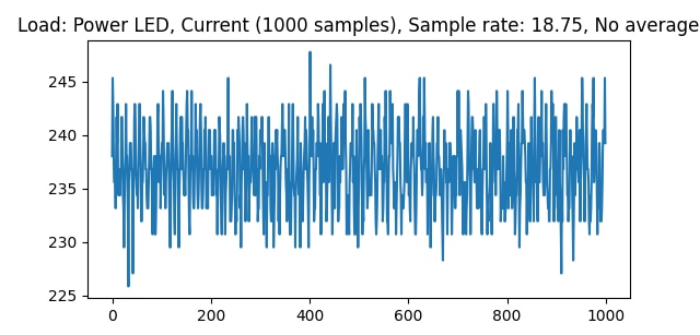
Fig.8
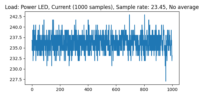
Fig.9
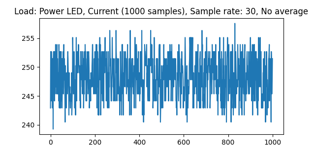
Fig.10
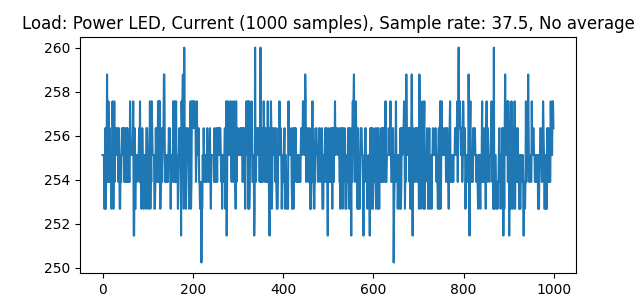
Fig.11
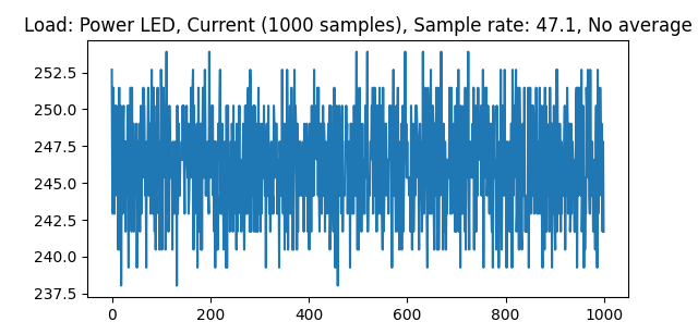
Fig.12

Fig.13
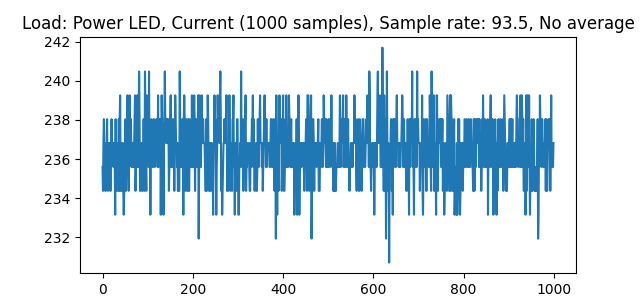
Fig.14
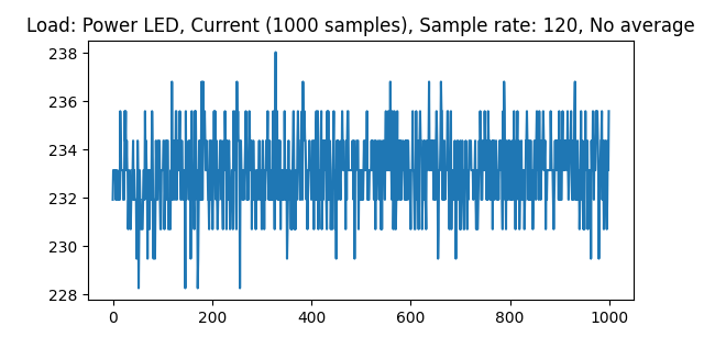
Fig.15
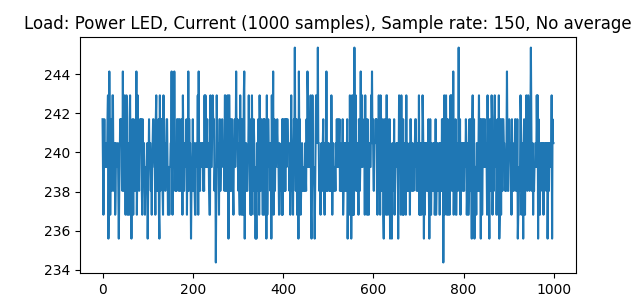
Fig.16
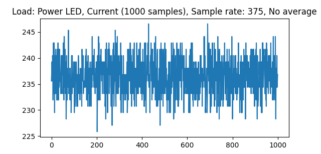
Fig.17
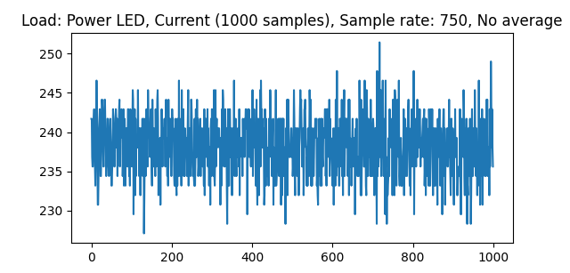
Fig.18
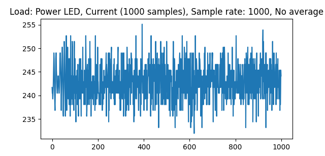
Fig.19
From the table and the graph, the change in accuracy or stability is not clearly observed. For calculating only the average current we can set any sample rate and it has no effect on the average output current. But for observing instantaneous current, transient and pulsating current, inductor/capacitor current for a high-frequency power converter, or ripple measurement in a high-frequency power circuit, setting a high sample rate can be more effective or advantageous.
Effect of changing Current Direction
The MAX40080 can measure bidirectional current. But does it measure the same in both directions? To get the answer I allowed to flow the same current in both directions and tried to observe if is there any notable change in the measured value. I did it for three different loads such as 1.2W, 2.4W, and 3.6W and measured the average current twice for every load. I also plot a graph every time for 1000 samples. I set the digital filter as 128 samples. The data I recorded is as follows:
| Sl No. | Voltage | Power | Direction | Measured Current | Graph |
| 1 | 4 V | 1.2 W | +Ve | 121.38 mA | Fig.20 |
| 2 | -Ve | -177.28 mA | Fig.21 | ||
| 3 | 2.4 W | +Ve | 379.14 mA | Fig.22 | |
| 4 | -Ve | -374.15 mA | Fig.23 | ||
| 5 | 3.6 W | +Ve | 389.03 mA | Fig.24 | |
| 6 | -Ve | -409.98 mA | Fig.25 |
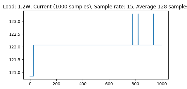
Fig.20
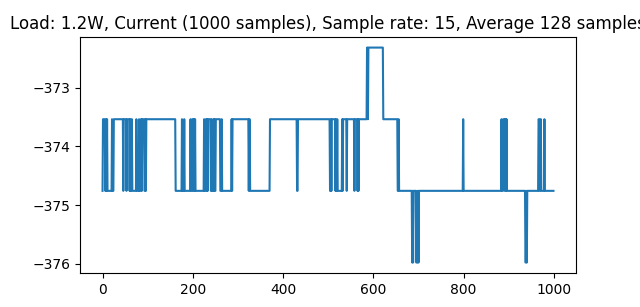
Fig.21
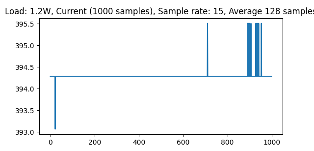
Fig.22
Fig.23
Fig.24
Fig.25
From the above data and graph, it is clearly observed that current measures in the two directions are slightly different. But it does not follow any specific rule and I have no right answer about this behavior at this time. Later I will try to discover more details about this behavior.
Comparing results with Nordic Power Profiler Kit II
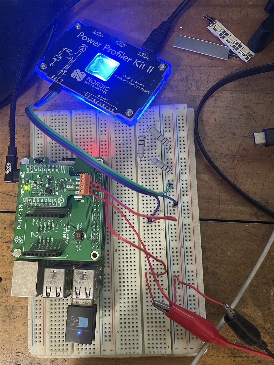
To know how accurate the measured current is, I compared the measured current using MAX40080 with the current measured by Nordic Power Profiler Kit II. Power Profiler Kit II can measure current from 200nA to 1A very accurately. This kit measures the current at a sample rate 100 ksps. The closest sample rate for MAX40080 is 93.5 ksps. So, I set the sample rate to 93.5 for MAX40080 current sense amplifier. For the first experiment, I connect both current sensors in series so that I can measure current by the two devices simultaneously. The following images show my circuit setup:

For keeping the current within 1 A I measured current for 1.2W, 2.4W and 3.6W LED panels using 4V power source.
Low Side (close to the ground): PPK 2, High Side (close to the power supply): MAX40080
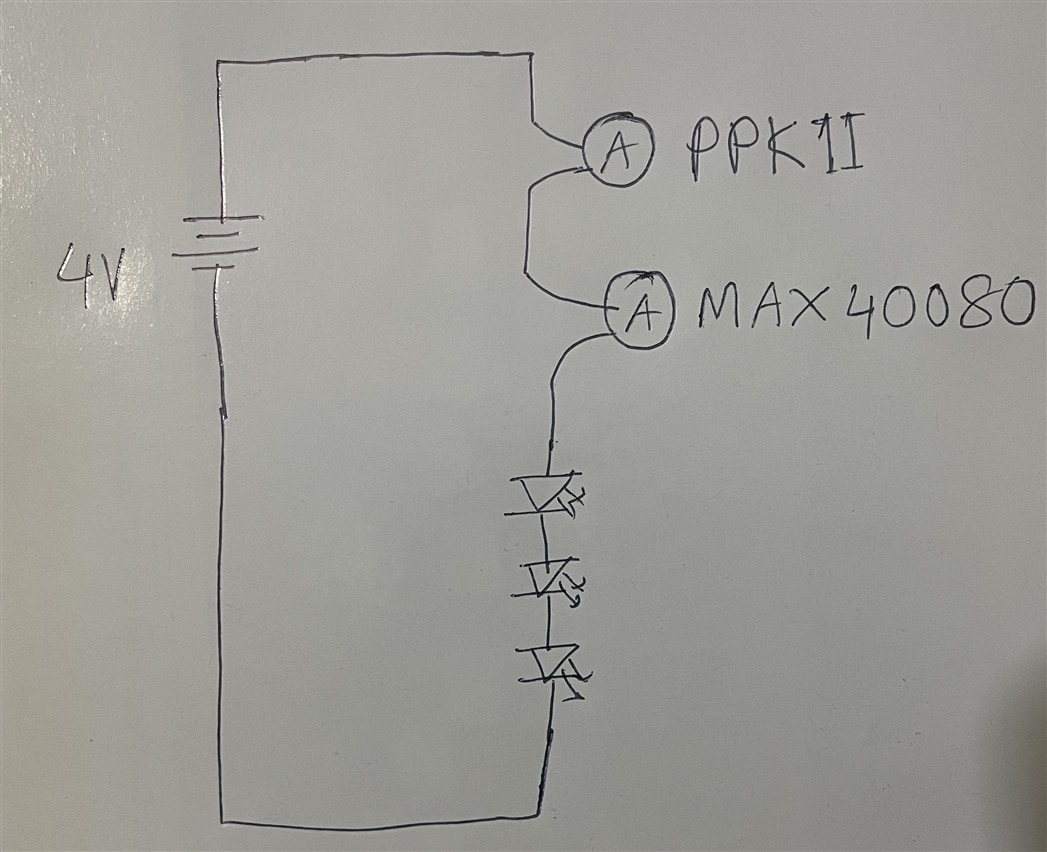
Fig: Position of PPK II and MAX40080 in the test circuit.
The tested data is given in the table below. I measured the average current three times for every load configuration. Figures show the measurement result for PPK II.
| Sl. No. | Load | Average Current (MAX40080) | Average Current (PPK II) | Graph |
| 1 | 2.4 W | 310.72 | 313.85 | Fig.26 |
| 2 | 308.53 | 310.45 | ||
| 3 | 309.40 | 311.17 | ||
| 4 | 1.2 W | 228.18 | 231.25 | Fig.27 |
| 5 | 226.55 | 228.19 | ||
| 6 | 225.89 | 228.76 | ||
| 7 | 3.6 W | 338.64 | 342.95 | Fig.28 |
| 8 | 344.82 | 347.13 | ||
| 9 | 342.11 | 344.47 |
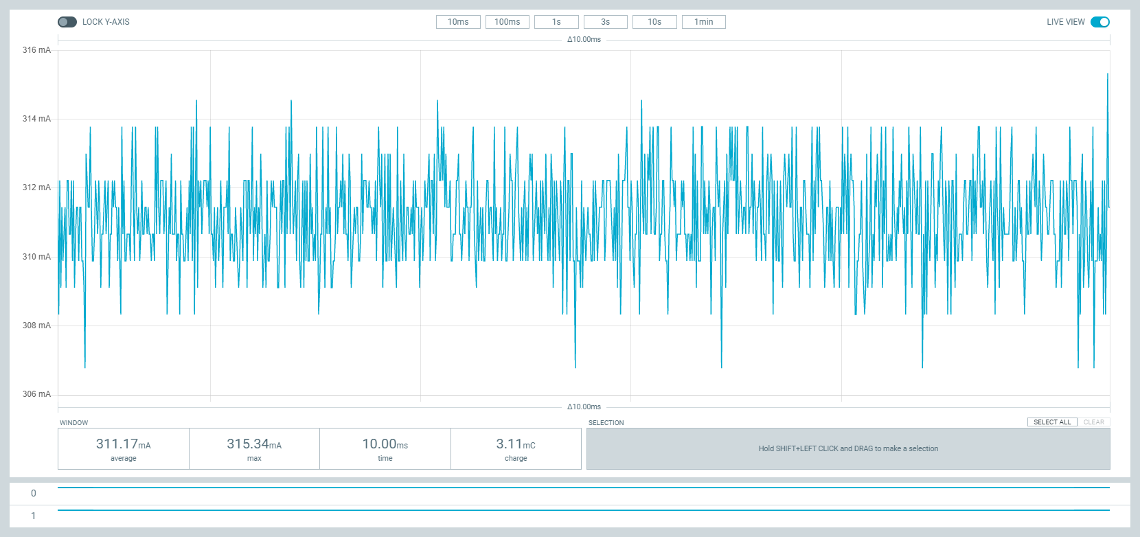
Fig.26
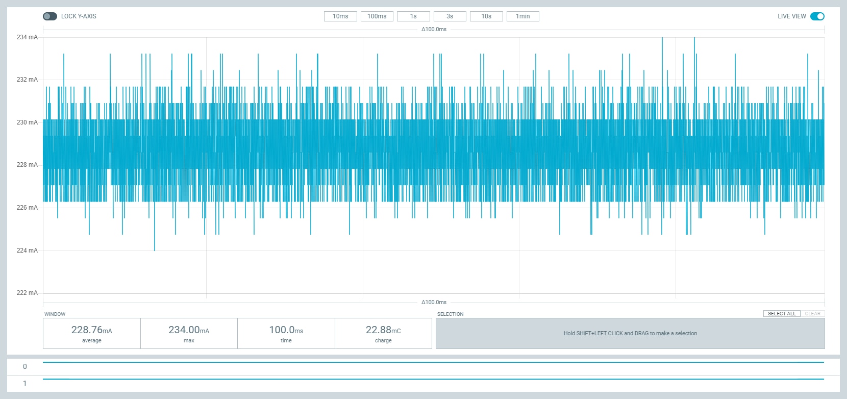
Fig.27

Fig.28
From the above data measured with both the kit simultaneously, it is clearly seen that the current measured by power profiler kit II is always 2-3 mA higher than the current measured by the MAX40080 current sense amplifier. I was surprised by this variation and suspect that it may be for the position of the sensors. So, I interchanged the position of the two measuring devices and now the PPK II kit is placed on the high side and MAX40080 was placed on the low side. But interestingly I observed the same result. As there is always the same gap between the two so we can say both sensors measure the current very accurately but MAX40080 current sense amplifier is calibrated slightly lower. I will investigate this in more detail in a later experiment.
High Side: PPK II, Low Side: MAX40080
| Sl. No. | Power | Average Current (MAX40080) | Average Current (PPK2) | Graph |
| 1 | 3.6 W | 271.32 | 274.33 |
Fig.29 |
| 2 | 2.4 W | 266.06 | 267.18 | |
| 3 | 1.2 W | 196.27 | 198.62 |
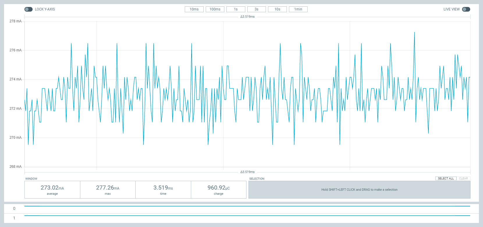
Fig.29
MAX40080 Direction Change
After completing the first experiment I tried to observe the current from the opposite direction more closely. As PPK II can not measure the current from opposite directions I only change the direction of the MAX40080 current sense amplifier. If MAX40080 can measure the same for both directions the difference should be 2/3mA. The sign or direction will not be an issue. But this time I observed slightly more variation between the two measured values. The MAX40080 shows more current than PPK II. So, we can conclude that MAX40080 does not measure the same amount of current as equal in both directions, for changing the direction we can get a slightly different value. I have no answer about the reason.
| Sl. No. | Power | Average Current (MAX40080) | Average Current (PPK2) | |
| 1 | 1.2 W | -178.99 | 175.66 | |
| 2 | -185.99 | 180.39 | ||
| 3 | 2.4 W | -238.33 | 231.89 | |
| 4 | -225.02 | 219.73 | ||
| 5 | 3.6 W | -265.33 | 259.34 | |
| 6 | -260.53 | 241.92 |
How much tiny current Current 6 Click can measure accurately?
In my previous blog, I tried to measure the sleep current of ESP8266 using the current 6 click but failed. That proves that the current 6 click is not capable to measure a very small current. SO, I want to know how minimum current the current 6 click can measure accurately. To find that I took 3, 100ohm, 1W resistors so that I can flow tiny current and I can very the current and measure it. First I use a 100ohm resistor as a load and measure the current using both the current sensing device. I provided 1V from the power supply to the resistor. According to the ohm's law, the current through a 100ohm resistor for 1V supply is 1/100 = 10mA. Nordic Power Profiler Kit II shows very accurate result which was 9.43mA which is very logical because wires has also some resistance. But I was not pleased with the result shown by MAX40080 based current 6 click. It shows 5.63mA which is only half of the actual current. Then I added another 100ohm resistor in series with the previous one. Still, PPK II shows very accurate result which is 4.86mA. The MAX40080 shows only 0.65mA which is very close to zero and may be the minimum current it can measure before showing a negative value. I added another 100ohm and like before get an accurate result from PPK II and very expectedly or unexpectedly MAX40080 shows a negative results.
The measured data is given in the following table:
| Sl. No. | Voltage | Resistance | Calculate Value | Average Current (MAX40080) | Average Current (PPK II) | Graph |
| 1 | 1 V | 100 ohm | 10 mA | 5.63 | 9.43 | Fig.30 |
| 2 | 1 V | 200 ohm | 5 mA | 0.65 | 4.86 | Fig.31 |
| 3 | 1 V | 300 ohm | 3.33 mA | -0.92 | 3.27 | Fig.32 |
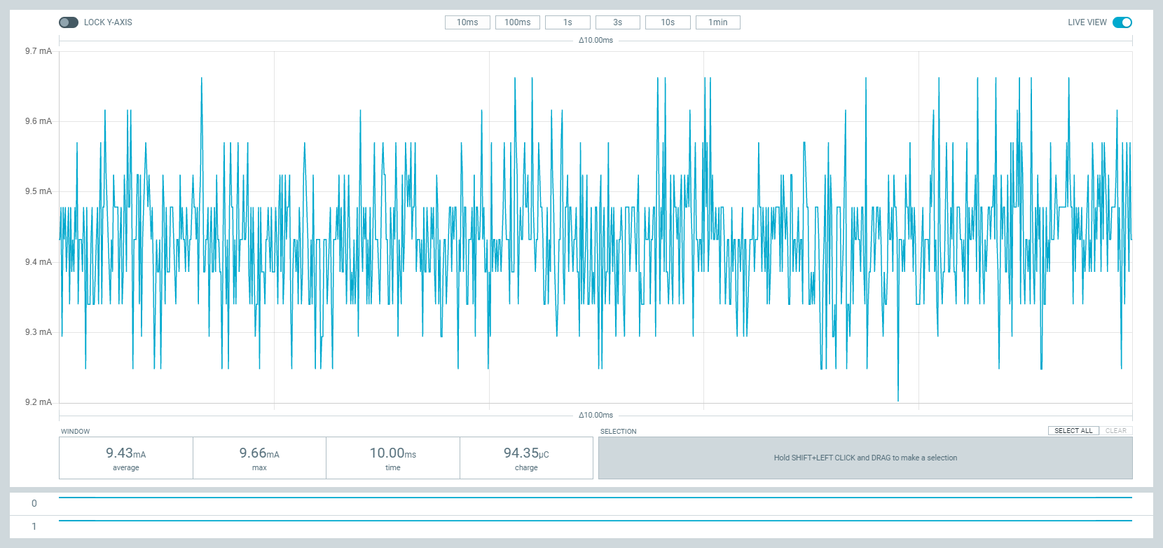
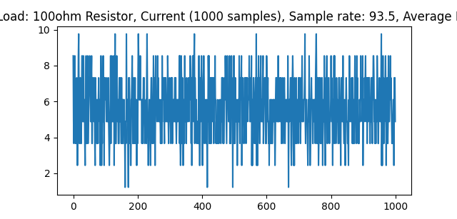
Fig.30
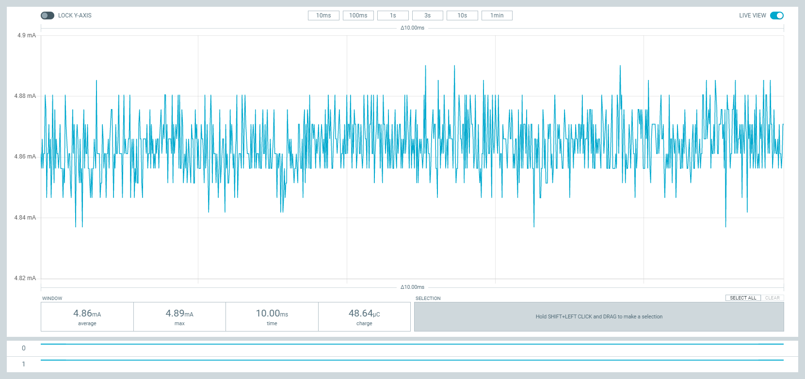

Fig.31

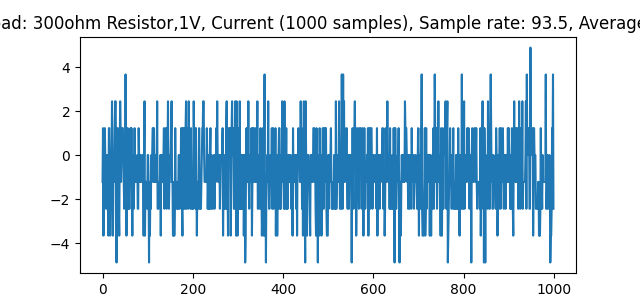
Fig.32
So, from the above test result, it is clear that MAX40080 is not showing a very accurate result for a tiny current of about a few milliamps. For the current less than 5mA, MAX shows a negative result. For even better understanding, I did the experiment using a 5W, 33ohm resistor and provided power from 0V to 5V incrementing 0.5V every time and measuring the current using both sensors. From the test data following graph was generated for better visualization.
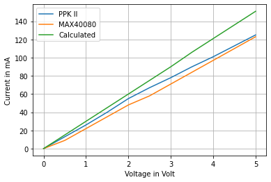
From the graph, it is clear that the value difference between the two measuring devices is not always the same. For the current above 100mA, the gap reduces gradually and may reach to zero after a certain value. For current around 40mA to 80mA the difference is maximum which is about 5mA.
We can also say that the Current 6 Click is not capable to measure a very small current like 5-10mA or below. Maybe increasing the value of the current shunt will help to overcome this limitation.
Effect of Changing Input Range or Gain
All the previous experiments were performed for the input range +/- 50mV which was the default input range in misaz python library. I did it first because there is no function in the python library I can use to change the input range or gain. So, I planned to modify the library to adjust the input range at the end of the experiments to make it work with +/-10mV. To do this experiment I manually changed the input range and gain inside the library source file and set it for 10mV.
Now, I will measure some current using two input ranges and compare both results with the Nordic Power Profiler Kit II
| Sl. No | Voltage (V) | Resistance (ohm) | Average Current MAX40080 (10mV) | Average Current MAX40080 (50mV) | Average Current PPK II |
| 1 | 0.5 | 33 | 11.06 | 7.03 | 11.61 |
| 2 | 1 | 23.09 | 21.52 | 23.54 | |
| 3 | 1.5 | 34.21 | 32.59 | 35.31 | |
| 4 | 2 | 49.65 | 51.14 | 49.98 | |
| 5 | 2.5 | 60.67 | 61.20 | 61.14 | |
| 6 | 3 | 74.56 | 73.56 | 74.87 | |
| 7 | 3.5 | 86.52 | 84.62 | 86.97 | |
| 8 | 4 | 95.30 | 96.17 | 95.64 | |
| 9 | 4.5 | 98.52 | 99.16 | 99.15 | |
| 10 | 5 | 125.98 | 127.23 | 126.25 |
From the table data following graph was generated.

From the data table and the graph, it is observed that for a very low current (less than 50mA) you will get a more accurate reading if you set the input range to 10mV. For more than 100mA load current I did not observe any significant effect of the input range on the accuracy. Even when the input range is 10mV, like the 50mV range I did not get any negative results when the current is less than 5mA. So, this 10mV input range is very effective for measuring the current close to zero mA.