element14 Community
element14 Community
    Register Log In
  • Site
  • Search
  • Log In Register
  • Community Hub
    Community Hub
    • What's New on element14
    • Feedback and Support
    • Benefits of Membership
    • Personal Blogs
    • Members Area
    • Achievement Levels
  • Learn
    Learn
    • Ask an Expert
    • eBooks
    • element14 presents
    • Learning Center
    • Tech Spotlight
    • STEM Academy
    • Webinars, Training and Events
    • Learning Groups
  • Technologies
    Technologies
    • 3D Printing
    • FPGA
    • Industrial Automation
    • Internet of Things
    • Power & Energy
    • Sensors
    • Technology Groups
  • Challenges & Projects
    Challenges & Projects
    • Design Challenges
    • element14 presents Projects
    • Project14
    • Arduino Projects
    • Raspberry Pi Projects
    • Project Groups
  • Products
    Products
    • Arduino
    • Avnet & Tria Boards Community
    • Dev Tools
    • Manufacturers
    • Multicomp Pro
    • Product Groups
    • Raspberry Pi
    • RoadTests & Reviews
  • About Us
    About the element14 Community
  • Store
    Store
    • Visit Your Store
    • Choose another store...
      • Europe
      •  Austria (German)
      •  Belgium (Dutch, French)
      •  Bulgaria (Bulgarian)
      •  Czech Republic (Czech)
      •  Denmark (Danish)
      •  Estonia (Estonian)
      •  Finland (Finnish)
      •  France (French)
      •  Germany (German)
      •  Hungary (Hungarian)
      •  Ireland
      •  Israel
      •  Italy (Italian)
      •  Latvia (Latvian)
      •  
      •  Lithuania (Lithuanian)
      •  Netherlands (Dutch)
      •  Norway (Norwegian)
      •  Poland (Polish)
      •  Portugal (Portuguese)
      •  Romania (Romanian)
      •  Russia (Russian)
      •  Slovakia (Slovak)
      •  Slovenia (Slovenian)
      •  Spain (Spanish)
      •  Sweden (Swedish)
      •  Switzerland(German, French)
      •  Turkey (Turkish)
      •  United Kingdom
      • Asia Pacific
      •  Australia
      •  China
      •  Hong Kong
      •  India
      •  Japan
      •  Korea (Korean)
      •  Malaysia
      •  New Zealand
      •  Philippines
      •  Singapore
      •  Taiwan
      •  Thailand (Thai)
      •  Vietnam
      • Americas
      •  Brazil (Portuguese)
      •  Canada
      •  Mexico (Spanish)
      •  United States
      Can't find the country/region you're looking for? Visit our export site or find a local distributor.
  • Translate
  • Profile
  • Settings
Experimenting with Current Sense Amplifiers
  • Challenges & Projects
  • Design Challenges
  • Experimenting with Current Sense Amplifiers
  • More
  • Cancel
Experimenting with Current Sense Amplifiers
Challenge Blog Blog #4: Getting it wrong. The Epiphany
  • Blog
  • Forum
  • Documents
  • Files
  • Mentions
  • Sub-Groups
  • Tags
  • More
  • Cancel
  • New
  • Share
  • More
  • Cancel
Group Actions
  • Group RSS
  • More
  • Cancel
Engagement
  • Author Author: colporteur
  • Date Created: 15 Apr 2022 1:11 PM Date Created
  • Views 2982 views
  • Likes 4 likes
  • Comments 11 comments
  • raspberry pi
  • current sense amplifier
  • MAX40080
Related
Recommended

Blog #4: Getting it wrong. The Epiphany

colporteur
colporteur
15 Apr 2022

Before nodding off in the early AM, I was rolling around the connection I proposed to measure the motor current using for the Current 6 Click sensor. Even when this challenge was in it's infancy, I made posts that reflected my uncertainty of how to connect the device to take measurements. Misza offered some suggestions but I still was not convinced I had a configuration that would work. As slumber was about to overtake me, I realized my connection proposal was wrong and would work once but then never again:( Sleep would have to wait!

image

The problem is the power bus voltage, the polarity reverses when the direction of the locomotive changes. That same voltage is the reference for the Current 6 Click device. When the locomotive is travelling forward Vin would be connected to the positive rail and GND connected to the negative. When the locomotive is made to travel backwards the voltage would reverse. Most devices I have used do not play well when the supply voltage or in this case the reference voltage is reversed! I suspect, the ground pin on the device being connected to a voltage was the nagging electronics at fault that invaded my sleep.

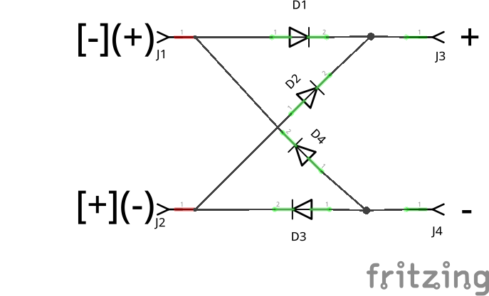
To put the connection demons haunting my shut-eye to rest, I got out of bed and sat at the desk trying to napkin design a solution. Something in the recesses of my mind suggested a bridge rectifier would solve this. Typically a bridge rectifier is used in a circuit to convert AC voltage to DC voltage. I recall seeing it used to prevent polarity reversal on power a connection, but how?
image

Please electronics aficionado's if I am in error tell me! I have yet to wire the device to a circuit. I need to get it right the first time or this challenge for me goes up in smoke. The two voltage polarities that can be reversed on the left are constantly translated to the right. The left would be connected to the power bus and the right to the Current 6 Click device. Voltage reversal problem solved (I think?).

I appreciate the power bus voltage will be reduced by the voltage drop across the two diodes before arriving at the Current 6 Click device. That voltage would vary as the speed of the locomotive is changed, so a voltage variance issue was anticipated.

I suspect this might impact the detection when the locomotive is moving at a slow speed. I have indicated in my first post speed testing voltages would be established as part of testing. That is one of the tests to determine if the circuit will still detect the locomotive motor.

I'm going to let this idea soak for a few days. No actual power connections during this soak period. I could really use a few thumbs up from the guru's to boost my confidence, if you happened to be reading by.

BACK TO NAPKIN FOR MORE EVALUATION

The bridge rectifier to adjust for polarity reversal suggested above will create a directional issue for the locomotive on the block of track the sensor is monitoring. That calls for another napkin. 
image

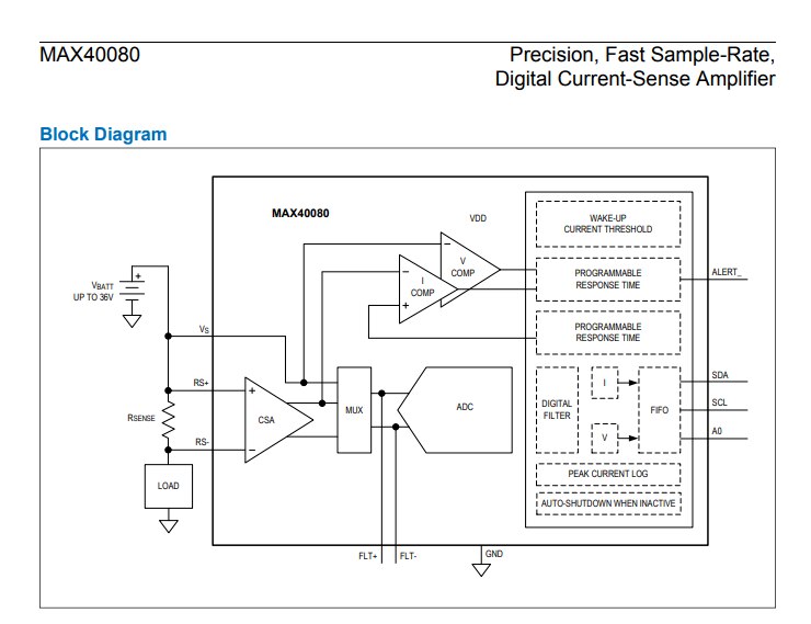
This MAX40080 chip schematic shows the load hookup. I just found a best practice recommendation that a DC current shunt should be connected on the grounded side of the load to minimize voltage present at the shunt and metering. I'm not sure how important that is for this circuit. I'm going to use the recommendation for my configuration.

The hookup I've planned without the bridge will work for the locomotive moving in one direction but creates an issue when the power bus polarity reverses for travel in the opposite direction. That indicates I can do testing in the forward direction for the DC system but not in the opposite direction. I have to remember to prevent a polarity reversal in my DC tests or I may damage the device.

The circuit should work for the DCC system since it doesn't use polarity on the rails to determine direction.

  • Sign in to reply
  • colporteur
    colporteur over 4 years ago in reply to jc2048

    I'm not understanding your explanation JC but in analyzing your feedback I see a flaw in my reasoning.

    This circuit is one block of track rail. The power bus voltage polarity determines the locomotive direction. Any locomotive entering this block of track rail will be forced to travel in a forward direction.

    • Cancel
    • Vote Up 0 Vote Down
    • Sign in to reply
    • More
    • Cancel
  • jc2048
    jc2048 over 4 years ago

    I don't think that works. With the bridge, you'll have the OV of the click board a diode drop above whichever of the controller outputs is most negative. One way round, the sense resistor will be close to the controller output that is most negative, so it will be below the 0V and blow the chip.

    • Cancel
    • Vote Up 0 Vote Down
    • Sign in to reply
    • More
    • Cancel
  • colporteur
    colporteur over 4 years ago in reply to dougw

    DC powered train system typically use a wire wound rheostat to lower the voltage. Maybe some of the newer power supplies are using PWM. I have about seven different models and the big wire wound resister is what I have found. That will need to be something I scope on the supply I am using to confirm.

    • Cancel
    • Vote Up 0 Vote Down
    • Sign in to reply
    • More
    • Cancel
  • colporteur
    colporteur over 4 years ago in reply to dougw

    To power the board it will rely on the Raspberry Power supply. Looking at the specifications Vin max is 36V.

    image

    Vin will be connected to the output of this modified bridge rectifier. The Max voltage for the power bus in my application will be 12V less the drops across the diodes.

    • Cancel
    • Vote Up 0 Vote Down
    • Sign in to reply
    • More
    • Cancel
  • dougw
    dougw over 4 years ago

    I am not quite clear what your circuit looks like.

    I don't know anything about the power system - if it is varying the voltage to adjust train speed or if it is using PWM, you may need to run the measurement system from the power supply instead of from the train power.

    • Cancel
    • Vote Up 0 Vote Down
    • Sign in to reply
    • More
    • Cancel
<>
element14 Community

element14 is the first online community specifically for engineers. Connect with your peers and get expert answers to your questions.

  • Members
  • Learn
  • Technologies
  • Challenges & Projects
  • Products
  • Store
  • About Us
  • Feedback & Support
  • FAQs
  • Terms of Use
  • Privacy Policy
  • Legal and Copyright Notices
  • Sitemap
  • Cookies

An Avnet Company © 2026 Premier Farnell Limited. All Rights Reserved.

Premier Farnell Ltd, registered in England and Wales (no 00876412), registered office: Farnell House, Forge Lane, Leeds LS12 2NE.

Follow element14

  • X
  • Facebook
  • linkedin
  • YouTube