


In this blog post, I will test the over-voltage and over-current protection features and charge a Li-ion battery with the Current 6 Click board using those features.
MAX40080 has a dedicated pin named as ALERT_ that indicates any overflow or underflow. Such a condition generates an interrupt. In the Current 6 Click board that pin is named ALR and it goes high if any overflow such as FIFO overflow, current overflow, or voltage underflow occurs. So, this is not very useful for individually identifying any overflow or underflow. To specifically detect any such event we need to check the STATUS register. The status register has a dedicated bit for every overflow and underflow. For our experiment, we need to detect over-current, over-voltage, and under-voltage. So, we are interested only in D2, D3, and D4 bits.
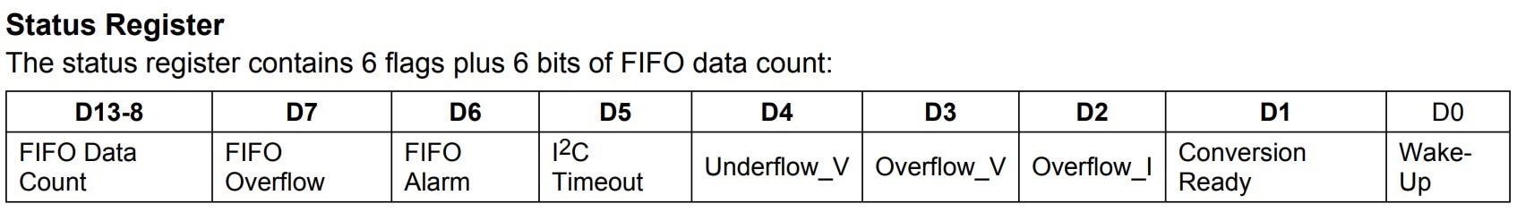
MAX40080 Status register's D2, D3, and D4 are for over-current, over-voltage, and under-voltage respectively.
Another three important registers for these features are Threshold_Over_Current, Threshold_Over_Voltage, and Threshold_Under_Voltage. These registers are used to set the threshold level of the related value.
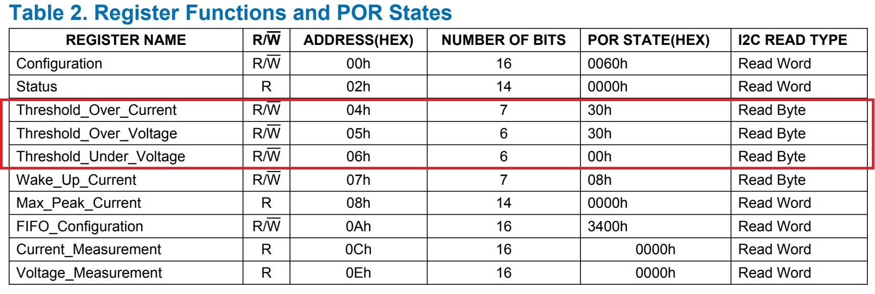
Let's, we want to set an over-voltage alert at 15 V. So, we need to store a specific value to the 0x05H register. This is a 6-bit register and the default value is set to 30H.
How to calculate the threshold value?
As Threshold_Over_Voltage is a 6-bit register the maximum value we can store in this register is b111111 which is 63 in decimal and 3F in hex. We know, that MAX40080 can measure a maximum of 36 V. So if we place 63 in the register it will set a threshold for 36V.
For the 15V limit, the threshold value will be ( 63/36 * 15 ) which is around 26 in decimal.
Same way, for the 300mA current limit, the threshold value for the Threshold_Over_Current register is ( 63 * current/1000 ) which is around 19 if the input range is set for 10mV or the maximum current is 1000mA.
How accurate the threshold is?
One downside of the 6-bit data value for the overvoltage or overcurrent threshold is that it is not very accurate. The maximum value we can store in a 6-bit register is 63 and this 63 is for 36V or 1000mA. So, if we consider the voltage, the minimum or maximum voltage we can set for the threshold is 36/64 = 0.56V or a multiple of 0.56V.
If we set an overvoltage alert for 4.5V it will not detect an overvoltage until 5.04V passes. So, the error here is around 0.5V and the maximum possible error is 0.56V.
We can do the same calculation for the current also.
How to clear the alert?
Every time an overflow or underflow is detected the corresponding bit is set. According to the datasheet, it remains set until it is cleared by writing the same value in the status register. So, for making clear any overflow we first need to read the status register and then write the same value to the status register.
My Python Code for Setting Overcurrent, Overvoltage, and Undervoltage Alert
For limiting the current and voltage I wrote the following test code. I used the misaz's Python library with some modifications and I wrote some new functions for setting threshold voltage and current. Using the code you can set and detect any overvoltage and overcurrent condition.
from max40080v import MAX40080V
import matplotlib.pyplot as plt
import time
import smbus
import crc
import RPi.GPIO as GPIO
GPIO.setwarnings(False)

max40080_addr = 0x21
bus = smbus.SMBus(1)

GPIO.setmode(GPIO.BCM) # Broadcom pin-numbering scheme
GPIO.setup(8, GPIO.OUT) # LED pin set as output
GPIO.output(8, GPIO.HIGH)

GPIO.setup(6, GPIO.IN)

max = MAX40080V()
max.configure(sample_rate_khz=15, digital_filter=1, measure_current=False, measure_voltage=True)

def calculate_crc(data):
    crc_parameter = crc.Configuration(8, 0x07, 0x00, 0x00, False, False)
    return crc.CrcCalculator(crc_parameter, True).calculate_checksum(data)

def read_16bit(reg_addr):
    buffer = bus.read_i2c_block_data(max40080_addr, reg_addr, 3)
    if calculate_crc([max40080_addr << 1, reg_addr, (max40080_addr << 1) | 0x01] + buffer[0:2]) != buffer[2]:
        raise Exception("Bad CRC received.")

    return buffer[0] | (buffer[1] << 8);

def write_16bit(reg_addr, data):
    buffer = [data & 0xFF, (data & 0xFF00) >> 8]
    buffer.append(calculate_crc([max40080_addr << 1, reg_addr] + buffer))
    bus.write_i2c_block_data(max40080_addr, reg_addr, buffer)

def write_8bit(reg_addr, data):
    buffer = [data & 0x3F]
    buffer.append(calculate_crc([max40080_addr << 1, reg_addr] + buffer))
    bus.write_i2c_block_data(max40080_addr, reg_addr, buffer)

def clear_overflow():
    value = read_16bit(0x02)
    write_16bit(0x02, value)

def check_overflow():
    value = bus.read_i2c_block_data(max40080_addr, 0x02, 3)
    if (value[0] & 0x04) == 4:
        print("Current Overflow")
    else:
        print("Current Normal")
    if value[0] & 0x08 == 8:
        print("Voltage Overflow")
    elif value[0] & 0x10 == 16:
        print("Voltage Underflow")
    else:
        print("Voltage Normal")

def set_current_limit(current):
    val = hex(round(63 * current/1000))
    value = int(val, 16)
    write_8bit(0x04, value)

def set_max_voltage(voltage):
    val = hex(round(63/36 * voltage))
    value = int(val, 16)
    write_8bit(0x05, value)

def set_min_voltage(voltage):
    val = hex(round(63/36 * voltage))
    value = int(val, 16)
    write_8bit(0x06, value)

def read_plot_current():
    measurements = []
    for i in range(100):
        value = max.read_current() * 1000
        measurements.append(value)
    print("Average( 100 samples):", (sum(measurements) / len(measurements)), " mA")
    #plt.plot(measurements)
    #plt.title('Current (100 samples), Sample rate: 15, No average')
    #plt.show()


set_max_voltage(15) #maximum 36
set_min_voltage(4.2) #minimum 0
#set_current_limit(300) #maximum 1000mA for 10mV input range and 5000 for 50mV


while True:
    read_plot_current()
    value = bus.read_i2c_block_data(max40080_addr, 0x02, 3)
    print("Status reg =", bin(value[0]))
    value = bus.read_i2c_block_data(max40080_addr, 0x04, 2)
    print("Current reg =", bin(value[0]))
    value = bus.read_i2c_block_data(max40080_addr, 0x05, 2)
    print("Ovoltage reg =", bin(value[0]))
    check_overflow()
    clear_overflow()
    time.sleep(1)
For setting current and voltage alerts simultaneously sample rate must be set to 0.5ksps. In my experiment, I tested over-voltage and overcurrent together by setting a sample rate 0.5. Show my experiment video below for over voltage and over current detection.
Charging & Discharging Li-ion Battery with protection
Li-ion battery is very sensitive to overvoltage (overcharging) and over-discharging. A sophisticated battery management circuit is required to protect a li-ion battery from overcharge and over-discharge. Again a controlled charging current should be maintained to keep battery health good for a long time. So, I set up an experiment circuit to maintain the voltage and current of a li-ion battery while charging and discharging. For load, I am using a small 3V DC Motor. See the image below:
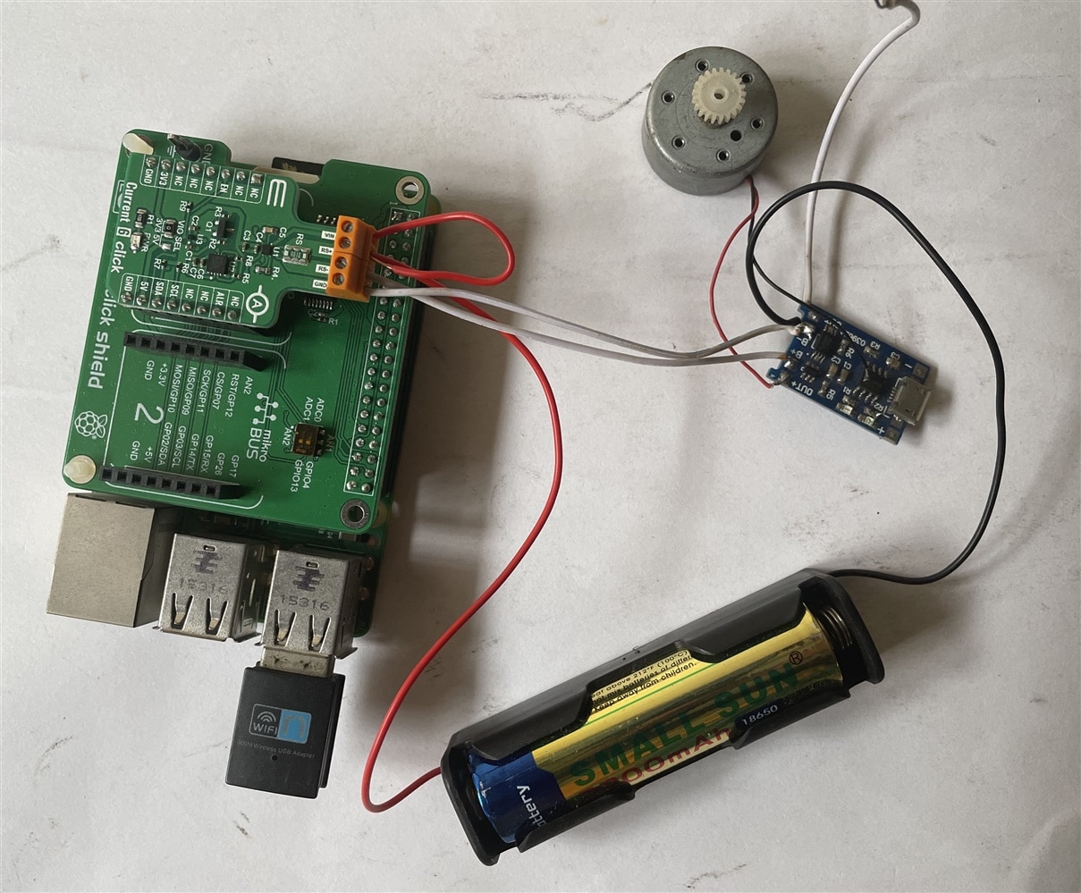
MAX40080 can be an option to use in a li-ion battery management circuit for overcharge and undercharge control with voltage and current monitoring.
Learning from the Current Sense Amplifier Contest
I have learned a lot from this challenge. I have gathered a lot of knowledge about the current sense amplifiers. Here are some topics I have learned from the challenge.
1. I learned about the current sense amplifier, current shunt, low side, and high side current sensing with advantages and disadvantages.
2. I learned about different types of the current sense amplifier and got a good knowledge about the MAX40080 current sense amplifier.
3. I learned about the different features of MAX40080 and the Current 6 Click board.
4. I learned different characteristics of MAX40080 current sense amplifier.
5. I got practical knowledge about current and voltage measurement using MAX40080 current sense amplifier.
6. I learned overvoltage and overcurrent detection of MAX40080 current sense amplifier
7. Throughout the experiments I realized that a current sense amplifier is really a good tool for current/voltage measuring and monitoring. These current sensing devices can be used in low power application circuits for precise current measuring. Overvoltage and overcurrent detection features can be utilized to protect a sophisticated circuit from overvoltage and overcurrent. Unlike other current measuring devices tiny form factor of the current sense amplifier makes them very useful to use in miniature circuit. Current sense amplifier can be used in smart home devices for power and energy monitoring. It can also be using in li-ion battery mangement circuit and power bank circuit for control, protection and monitoring.
