


This is the final post for the challenge. I have been in a holding pattern of trying to finish the challenge. In blog#7 I provided a picture of the water coverage in the area. I completed bench testing and was ready to put the locomotive on the rails and record some results. Flooding prevented me from getting to the model railroad site (farm).
It normally takes less than ten minutes to get to the farm from my home in town. With flooding, it took close to an hour to get to a road that crosses the rail line and then a 3/4 mile walk down the line to reach the farm. The video is a short clip of conditions. The farm is in the corp of trees at the end of the rail line. To gather data to complete the challenge I went for a drive and then a walk on the rail line.
Attached is a spreadsheet of results from eight tests. I can't figure out how to post the spreadsheet data!
The yellow highlight areas are when the locomotive enters the monitored rails.


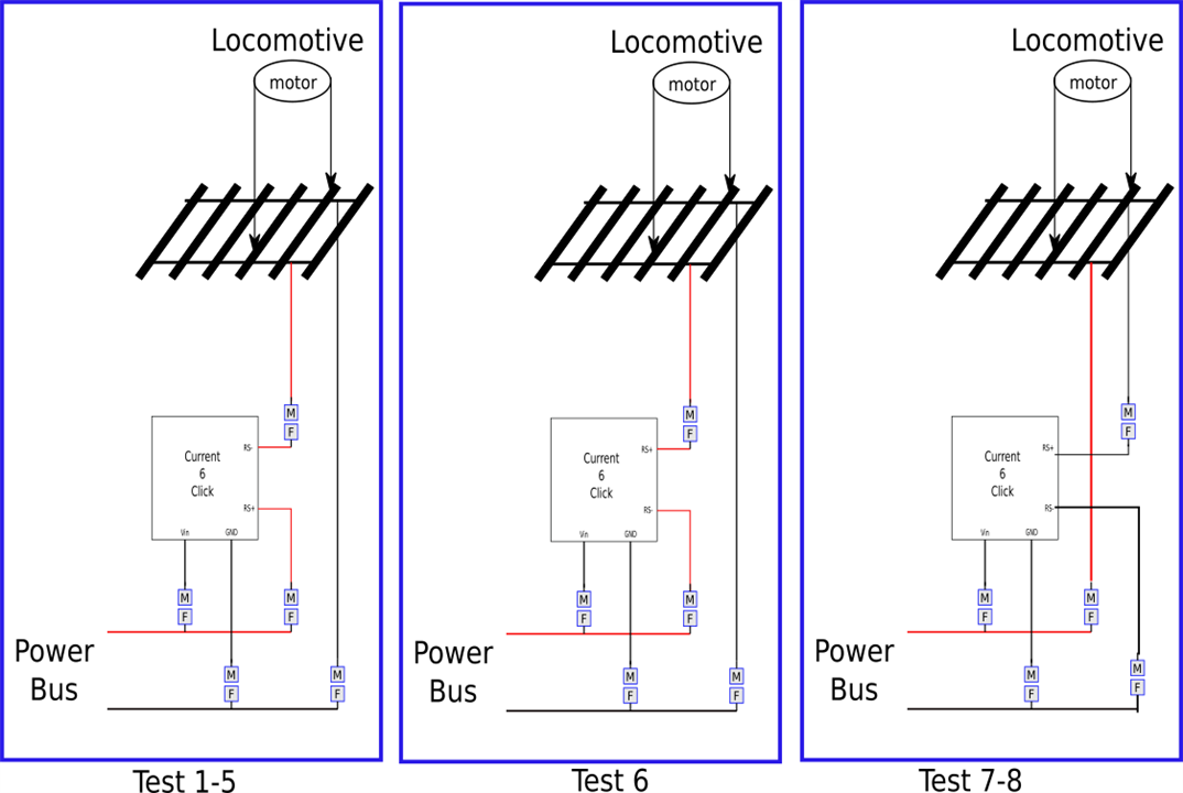
The eight tests were done using three hardware configurations. Below is a brief description of each test.
Test1:Tech II Railmaster 2400 power supply connected to the power bus. A VOM is also attached to the power bus to get a reading called Meter. Meter= 5.15VDC
Test2:Tech II Railmaster 2400, Meter= 8.28VDC
Test3:Tech II Railmaster 2400, Meter= 9.08VDC
Test4:Buck/Boost Module, Meter= 4.85VDC
Test5:Buck/Boost Module, Meter= 8.82VDC
Test6:Buck/Boost Module, Meter = 4.85VDC, RS- & RS+ reversed
Test7:Buck/Boost Module, Meter= 4.85VDC, RS- & RS+ low side of load
Test7:Tech II Railmaster 2400, Meter= 5.5VDC, RS- & RS+ low side of load
Extensive testing was done to try and discover why the Click6 voltage measurements didn't seem appropriate. Bench testing the locomotive the Click6 voltage measurement aligned with the power supply voltage. It did not during the rail tests. The Click6 measured voltage measurement is greater than the voltage applied to the power rails.
At first, I thought it was caused by the Tech II Railmaster 2400 variable power supply used for operating DC locomotives (Test1-3). This thought proved wrong because when I used the same power supply that was used for bench testing, anomaly results were recorded also (Test4-5). Test6 I reversed where RS- & RS+ were connected. This proved wrong because no readings were recorded. Test 7-8 had the Click6 connected on the other side of the load. Again the voltage anomaly existed.
What was different between the bench test and the rail test was where the Click6 was connected.
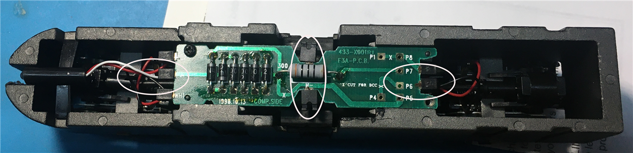
The connection in the center of PCB in the locomotive chassis goes to either side of the motor. This is the location where the bench power supply was connected. The connection at either end of the PCB is connected to the trucks (wheels) on the locomotive. This is where the rail power supply was connected. I'm going to speculate the increase (doubling) in the current sense readings is because first one truck is in the measurement and then the second touches the rail.
I don't have a schematic for the PCB. It looks like it contains a resistor and multiple diodes. The board provides a connection point if the modeler wanted to add lights.
I don't have a reason why the voltage measured by the Click6 is higher than the power supply.
Summary
My objective was to uncover some knowledge in Block Detection, a model train practice. Working on this challenge has met that object and then some. Block Detection using rail power has challenges.
I also planned to test the hardware on both a DC and DCC system. I discovered the hardware would not work on the DCC system because the Power Bus on a DCC system is an AC voltage and not DC voltage as I assumed.
My thanks to the challenge committee for selecting my application. My initial response after receiving the equipment was to withdraw from the challenge to give someone with more skills a chance to participate. There was no python library provided by the equipment vendor. I don't have the skills to develop one. I continued with the challenge after encouragement from the committee and after reading misaz post. I asked misaz if I could use the python library once it was developed. Using that library was the key to being able to continue.