


In today's blog, I'd like to give a current update on the current state of my current project monitoring current.  TL;DR - I've got my hardware test rig working, and a Python script talking to the module, but ran into an issue being able to write values out to the device. I've unfortunately been pretty distracted the past couple of weeks and haven't been able to work on this. I'm back now and plan on cranking away over the final two weeks before the end. Scroll all the way down for a video overview.
What am I building?
My project is designed to monitor the current going out to the nozzle (or heated bed) of a 3D printer. By paying attention to those values, I think it is possible to detect fatigued or loose wires, and also short circuits. Coupled with a relay (or MOSFET) we could disconnect the power going to the device and have a safe shutdown.
Hardware layout
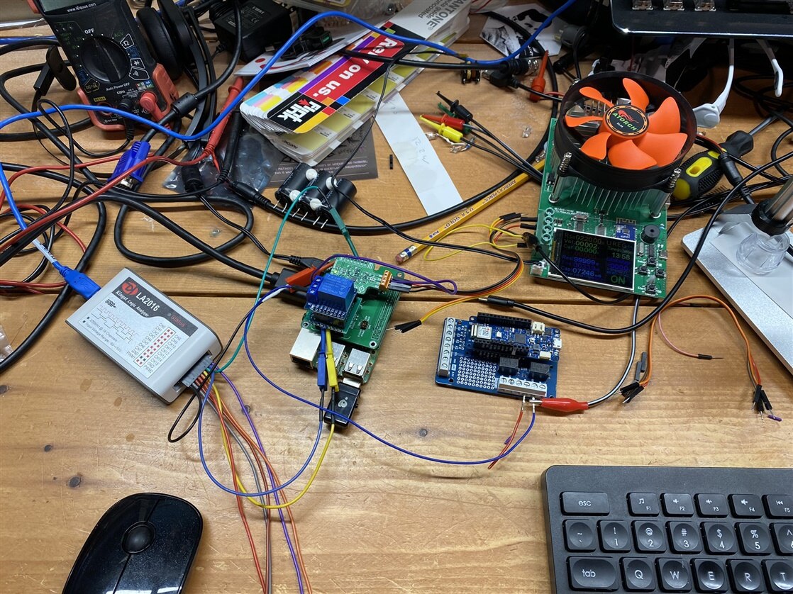 Yup - bench is delightfully messy today :) I have assembled my hardware setup for this project as follows...This is using all bench equipment. If this were to be implemented, it would be made more compact and built into a 3D printer control board.
I've got a bench power supply that I will ultimately be pushing a couple amps @ 24v. During testing so far I've dialed it back to 5v with a pretty low current limit. I am using a DC load at the other end to create the current draw. I have this dialed back to 220ohms (constant current mode) or about 20 mA - LED territory in terms of power draw; but keeping things safe until more pieces are assembled and working.
The power from my bench supply goes through two relays - the first relay is on a separate Arduino which will be running 'blink' to pulse the power on and off. This will simulate a 3D printer cycling its MOSFET to enable/disable power to the hotend. The second relay is part of my project. It is the safety backup way of disconnecting power when a fault is detected. I'm using a relay shield from a D1Mini for this, and made a simple adapter board to get it to plug into the Click Shield; and am controlling it from my Python sketch.
Software
I was planning on running PyCharm on the RaspberryPi as my development environment for Python, but wasn't able to get it operational. I wasted about two evenings trying to get it going. It kept throwing an 'out of memory' error for Java. I did some digging and found tips to reduce the stack size that JDK allocates, but wasn't ever able to get PyCharm to get past the splash screen. I later caved in and went with Thonny on the Pi. It isn't as polished as PyCharm, but it does the trick. I lose the realtime syntax checking and intelletype and simple GIT integration that I love with Pycharm, but I'm able to code and debug.
My code is currently about 120 lines of Python. I'm trying to make it simple and so aren't using really much with creating my own libraries or some functions of OOP. Just piling everything into one big file
The code use RPI.GPIO to control the IO; complete with some interrupt functions for when the 'alert' pin is asserted on the Current6Click. It also uses the SMBus library to talk over the I2C lines.
So far my code can toggle output pins as required (like the Current6Click 'enable' and to turn on my relay), and I'm able to have a 'one-sided' conversation with the MAX40080 chip which is the brains of the Current6Click board. I can read the appropriate registers and I'm getting valid data back that matches what the Datasheet says they should be.
But I'm stuck!!!
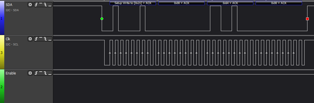
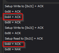 The part I'm stuck at now is that I can't seem to do any proper 'writes' to the MAX40080. The SMBus library handles all the low-level communications and I can use the i2cbus.write_word_data() command; but the data doesn't seem to 'stick.' I pulled out my logic analizer and am probing the SDA/SCL lines and everything I see here seems to match the MAX40080 datasheet; but when the register is read back, it still has the previous data stored. I've read through the data sheet multiple times but surely am still missing something.his image shows sending down a 0x64 configuration into register 0x00; but when I read back afterwards, it is still at the default 0x60 value. I've tried multiple different registers and I don't see any sort of write-protect bit or some other 'enable'.
Of course, for those following the others in this competition may already know the answer because I'm sure that someone else already ran into this. I however, have made a point to avoid reading the other blogs and spent a few extra evenings trying to find the answer myself. But alas, I'm still stuck. So after posting this, I'll be browsing through the other posts to see what they've found.
My Code
If anyone is interested, here is my code as of tonight.
import RPi.GPIO as GPIO
# import board
# import busio
# i2c = busio.I2C(board.SCL, board.SCA)
from smbus import SMBus
import time

current6ClickAddress = 0x21
CurrentSenseEnablePin = 8
OvercurrentAlertPin = 6
RelayPin = 26

GPIO.setmode(GPIO.BCM)
GPIO.setup(CurrentSenseEnablePin, GPIO.OUT)
GPIO.setup(RelayPin, GPIO.OUT)
GPIO.setup(OvercurrentAlertPin, GPIO.IN)


#Create Instance of SMBus to talk to device
i2cbus = SMBus(1)


#enable relay
def enableRelay():
    GPIO.output(RelayPin, GPIO.HIGH)

def disableRelay():
    GPIO.output(RelayPin, GPIO.LOW)

def readConfig():
    myval = i2cbus.read_word_data(current6ClickAddress, 0x00)
    print('config: ', hex(myval))

def setConfig():
    myval = i2cbus.read_word_data(current6ClickAddress, 0x00)
    #char writebuf[2] = {0x00, 0x62}
    myval = myval | 0b00000110 # enable Active mode with bits 1,2.
    myval = myval | 0b00001000 # disable I2C Timeout
    print("new config: ", hex(myval))
    i2cbus.write_word_data(current6ClickAddress, 0x00, myval)
    time.sleep(0.05)
    mynewval = i2cbus.read_word_data(current6ClickAddress, 0x00)
    print('config: ', hex(mynewval))

def readStatus():
    myval = i2cbus.read_word_data(current6ClickAddress, 0x02)
    print('Status: ', hex(myval))

def readOverCurrentThreshold():
    myval = i2cbus.read_byte_data(current6ClickAddress, 0x04)
    print('Overcurrent Threshold: ', hex(myval))

def readVoltage():
    myval = i2cbus.read_word_data(current6ClickAddress, 0x0E) #0x0E is address for voltage
    print(myval)

def readAmps():
    myval = i2cbus.read_word_data(current6ClickAddress, 0x0c) #0x0c is address for current
    print(myval)

def setOverCurrentThreshold():
    i2cbus.write_byte_data(current6ClickAddress, 0x04, 0x31)
    myval = i2cbus.read_byte_data(current6ClickAddress, 0x04)
    print('Overcurrent Threshold: ', hex(myval))
    pass

def overcurrentDetect_callback():
    print("Overcurrent detected!")
    disableRelay()
    pass

GPIO.add_event_detect(OvercurrentAlertPin, GPIO.RISING)
GPIO.add_event_callback(OvercurrentAlertPin, overcurrentDetect_callback)

def setup():
    #enable the current sense pin on Current6Click
    GPIO.output(CurrentSenseEnablePin, GPIO.HIGH)
    time.sleep(0.25)

    #readStatus()
    #readConfig()
    setConfig()

    #readOverCurrentThreshold()
    #setOverCurrentThreshold()
    #readStatus()


def main():
    print("Program starting")

    n=0
    while n <10:
        enableRelay()
        readVoltage()
        readAmps()


        time.sleep(.5)
        disableRelay()
        time.sleep(.5)
        n+=1

try:
    if __name__ =="__main__":
        setup()
        main()

except KeyboardInterrupt:
    print("Keyboard interrupt detected")
    #catch any Cntl+C exits
    pass

except Exception as e:
    print("Exception")
    print(e)
    pass

finally:
    print("cleaning up")
    GPIO.cleanup()
And Finally - a video!
2-minute video showing the status of the project as of tonight.
-

aspork42
-
Cancel
-
Vote Up
0
Vote Down
-
-
Sign in to reply
-
More
-
Cancel
-

misaz
in reply to aspork42
-
Cancel
-
Vote Up
0
Vote Down
-
-
Sign in to reply
-
More
-
Cancel
Comment-

misaz
in reply to aspork42
-
Cancel
-
Vote Up
0
Vote Down
-
-
Sign in to reply
-
More
-
Cancel
Children