


Hello again!
I'm looking at how to use a Current Sense Amplifier to make a safer 3D printer. By monitoring the current going out to the printer's nozzle and heat bed, we can detect loose/broken, and shorted wires.
Where am I at with all this?
 Well - I'm at two places! I'm at a pretty good place with the project where I can nearly say I've achieved all my goals. I'm also traveling in Michigan this week; away from my normal Milwaukee. I'm visiting my mom for the weekend and brought my kit along to keep things rolling. I'm now able to have the MAX40080 take all my measurements, and a Python script control a relay to cut power if a fault is detected.
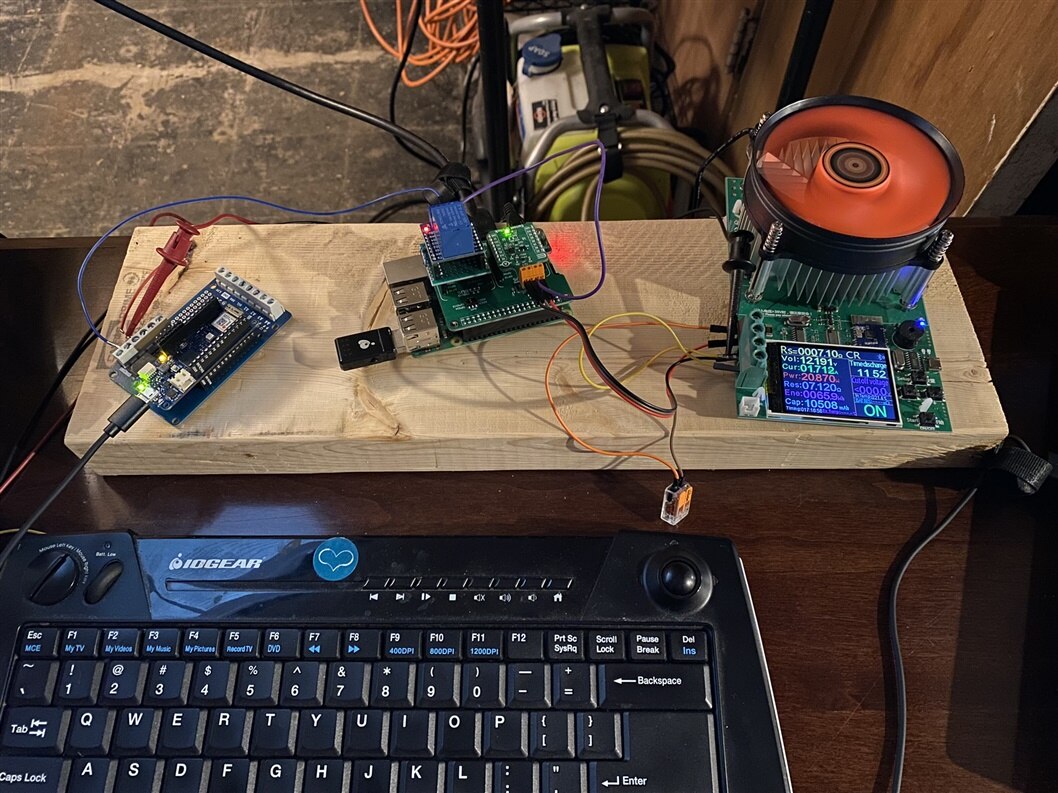
I'm working in a half-finished (mid-remodel) basement on a tiny table with minimal supplies, but making the most of it  Image to the left shows my bare-bones setup.
Skip to the end
If you'd like to see a 3-minute video update.
What else is left?
I've got two lingering things that I need to work out. I has stated originally that I was going to use MQTT to control this; and so far I haven't added that in yet. I'm not super concerned about this as it was more of a bonus for monitoring & control. The second issue is something I found in testing. I have one additional relay being run via a Blink sketch on an external Arduino. this clicks on and off to simulate the 3D printer using a MOSFET to turn the nozzle on and off. It looks like when the relay shuts off, the MAX40080 is reading fast enough to see the current drop to zero before the voltage and sees this as a fault. When the current drops to zero, my device still sees 12V, without any current flowing and kills the system. This would be a condition of broken/loose wiring (using high-side current sensing). This is where I tried turning to averaging on-board the 40080 which caused a bunch of other issues; and then started trying to average in Python instead. The downside of this approach is it cuts down reaction time of the system. This means I have my next problem to solve! I also don't know if this has to do with using a relay instead of MOSFET, or using the inexpensive digital load verses how a normal resistive load would behave.
Updates since the last blog?
In Blog #3, I was having issues talking to the device. It turned out that I was missing sending a CRC checksum. I figured this out after posting that write-up by checking a few competitor's blogs (which I've been avoiding as much as possible; to not get distracted). I think I was mis-reading the datasheet and assuming that CRC was disabled; but it was not. So add in a few more nights trying to manually calc the CRC and then messing with libraries before finally giving it a pass and just disabling and moving on. At least the data we get back from the device has a "Data Valid" bit that must check out before proceeding.
Once I got past this barrier, I could start setting all the bits in memory that I wanted to play with. It was really starting to look like almost my entire program could be interrupt-drive, but looking at the notes below, this failed. I had to achieve this all in code.
Problems with the Datasheet (and/or chip)(and/or me)
There were some issues I ran into with the datasheet - although to be fair it may be my interpretation of the data sheet; or a misunderstanding of some features of the chip. Take for instance the High/Low range for current measurement. The data sheet only notes High/Low range for 50mv/10mv. It doesn't spell out how this corresponds to the data readings it will produce. It isn't directly even spelled out what this 50/10mv even refers to (assuming its the CSA input voltage? But that's determined by the current shunt resistor; so that doesn't even make sense). For reading back values, it turns out that it becomes up to the user to "multiply by five" the current output when going into High Current mode. So by setting this bit, my current readings were just reduced by a factor of five. This isn't noted in the Range section or the measurement sections. I work in engineering and constantly have to remind my peers that what they consider 'obvious' isn't really obvious at all to the outside world; to people who didn't design the 'thing' and haven't worked with the 'thing' daily for years. They need to make things easy and simple for the general userbase who don't have as much deep technical knowledge.
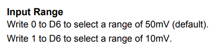
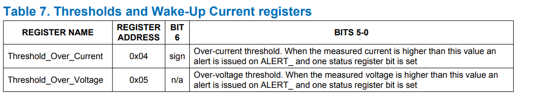
Another issue is that of units. Most the datasheet doesn't seem to spell out units/ranges/scaling for setpoints. I can see the number of bits and the address, but not what the corresponding value is supposed to relate to. See images below. We have a 12-bit number for the current & voltage magnitude, and a 6-bit value for the threshold used in the interrupt. No where is it correlated how do do the conversion from volts/amps to this value. Again, there is no notes of how high/low range change the values that need to be placed into these registers. my best guess was to correlate input max/min for the given range, and then scale my 6-bit value accordingly. I could verify that my writes were being done properly, but the alerts never came. How does changing High/Low range affect these values?

I know that this will return 16 bits of data, with the current magnitude in D11-D0, but I don't know Amps, milliamps, etc; so where does my decimal go?
Digital Filter - Turning on filtering caused all sorts of interrupts and alerts. I wanted to do averaging right on the chip but ultimately had to do this in code because the chip seemed to freak out. I was getting overcurent and overvoltage interrupts like crazy. It seemed like perhaps the chip was trying to do averaging internally, and the rolling tally was counted against the alert threshold; rather than the averaged value.
Interrupts - I had wanted to use Overvoltage interrupt to tell my application to start monitoring current because the printer was running the nozzle. I couldn't figure out how to get any suitable value that fired this interrupt though (since no guidance on how to set and my playing around didn't yield anything productive). Undervoltge would then also tell me that the printer is no longer asking the nozzle to run; so don't monitor current. But I couldn't get this to fire reliably. Then Overcurrent was also going to be most useful for detecting shorted wires. But again, I couldn't get this to fire. I played around with masking the faults and basically had to mask the FIFO because it was constantly complaining about being full. So I ignore it and tell the chip not to alert me about it.
To Fifo or Not to Fifo? The chip has a First-in-first-out buffer for measurements. When a read is performed, it goes to the next spot in this FIFO. It internally handles knowing which measurement was the last read. I also spent a decent amount of time messing with the settings for the Fifo. As noted above, I was assuming that the chip would just "read continuously" as per the setting I used. Then I could use the interrupts to tell me when I needed to know something. That would have been the fastest response time and simplest to code, but it didn't work. So then I don't understand the FIFO buffer - why not just use Single Measurement Mode and not bother with Fifo? In the end, I needed to manually read the chip and it would always complain that the FIFO was full; but only when I read; never else would it complain. So it seemed like the chip was doing single conversion mode. I really don't care about each individual measurement, I just wanted to know when they go out of bounds. But disabling the FIFO causes the readings to be blank; so I had to leave it on... why? And why was it always full? I also had to enable Roll-Over otherwise it seemed like it was still in single-conversion mode and I was getting really stale data. Even flushing the FIFO didn't resolve anything and I just got zeros for my measurements.
Also, I found that the Fifo doesn't store voltage by default, so I had to turn that on as I need it. There is perhaps an argument on what should be 'default' here, but I'd argue that it should be storing voltage by default also. So I was getting all zeros until this was done.
My Code
If anyone is interested, here is the complete code that was running in the video shown on this blog post.
import RPi.GPIO as GPIO
# import board
# import busio
# i2c = busio.I2C(board.SCL, board.SCA)
from smbus import SMBus
#from PyCRC.CRCCCITT import CRCCCITT

# import crc8

import time

activeInterrupt = False # to handle interrupt pin

InputRangeHigh = True # True for 5Amp limit. False for 1Amp limit

current6ClickAddress = 0x21
CurrentSenseEnablePin = 8
OvercurrentAlertPin = 6
RelayPin = 26

myMaxCurrent = 2
myMinCurrent = 0.3
myTurnOnVoltage = 10  # when to start assuming that the system is running
myTurnOffVoltage = 2

GPIO.setmode(GPIO.BCM)

GPIO.setup(CurrentSenseEnablePin, GPIO.OUT)
GPIO.setup(RelayPin, GPIO.OUT)
GPIO.setup(OvercurrentAlertPin, GPIO.IN)


#Create Instance of SMBus to talk to device
i2cbus = SMBus(1)

#enable relay
def enableRelay():
    GPIO.output(RelayPin, GPIO.HIGH)

def disableRelay():
    GPIO.output(RelayPin, GPIO.LOW)

def setConfig():
    global InputRangeHigh

    myval = i2cbus.read_word_data(current6ClickAddress, 0x00)
    print("Starting Config: ", myval)
    myval = 0x00 # disable Packet Error Checking (PEC); leave all other values at default.

    i2cbus.write_i2c_block_data(current6ClickAddress, 0x00, [myval, 0x00, 0xB7]) # Disable PEC

    #i2cbus.write_i2c_block_data(current6ClickAddress, 0x00, [0x7e, 0x00, 0xc3])

    # Configuration register
    myval = myval | 0b00000011 # enable Active mode with bits 0,1.
#     myval = myval | 0b00001000 # disable I2C Timeout
    myval = myval | 0b00010000 # Alert response time. 0=unfiltered. 1= four consec. readings
#     myval = myval | 0b00100000 # PEC
    if not InputRangeHigh:
#         print("Disable High Current Range")
        myval = myval | 0b01000000 # Input Range - write 1 for Low (5Amps max)

#     myval = myval | 0b10000000 # Stay HS Mode

    print("proposed config: ", hex(myval))

#     Digital averaging - makes erratic faults and readings :(
    myval = myval | 0x0000 #no average
#     myval = myval | 0x1000 #average 8
#     myval = myval | 0x2000 #average 16
#     myval = myval | 0x3000 #average 32
#     myval = myval | 0x4000 #average 64
#     myval = myval | 0x5000 #average 128

#     print("proposed config: ", hex(myval))

    i2cbus.write_word_data(current6ClickAddress, 0x00, myval)
#     i2cbus.write_byte_data(current6ClickAddress, 0x00, myval)

#     myval = i2cbus.read_word_data(current6ClickAddress, 0x00)
#     print("Config now in chip: ", hex(myval))

    #Fifo settings
#     myFifo = i2cbus.read_word_data(current6ClickAddress, 0x0A)
#     print("Startup Fifo config: ", hex(myFifo))

    myFifo = 0x0000
    #myFifo = myFifo | 0x8000 # flush
    #myFifo = myFifo | 0x0003 # disable fifo
    myFifo = myFifo | 0x0002 # fifo for V & C
    myFifo = myFifo | 0x4000 # enable rollover of Fifo

    i2cbus.write_word_data(current6ClickAddress,0x0A, myFifo)

#     myInts = i2cbus.read_byte_data(current6ClickAddress, 0x14)
#     print("Interrupts currently set: ", myInts)

    # configure interrupts
    myInts = 0x0
    myInts = myInts | 0b00000001 # wake-up enable
    myInts = myInts | 0b00000010 # Conversion ready
    myInts = myInts | 0b00000100 # Overflow current
    myInts = myInts | 0b00001000 # overflow Volts
    myInts = myInts | 0b00010000 # Underflow Volts
    myInts = myInts | 0b00100000 # I2C Timeout
    myInts = myInts | 0b01000000 # Alarm overflow
#     myInts = myInts | 0b10000000 # Overflow Mask **Need to disable this to avoid overflow interrups
#     print("Proposed Interrupts: ", myInts)
    i2cbus.write_byte_data(current6ClickAddress, 0x14, myInts)
#
#     myInts = i2cbus.read_byte_data(current6ClickAddress, 0x14)
#     print("Interrupts currently set: ", myInts)

#     myFifo = i2cbus.read_word_data(current6ClickAddress, 0x0A)
#     print("New fifo on chip memory: ", hex(myFifo))

#     time.sleep(0.1)
#     mynewval = i2cbus.read_word_data(current6ClickAddress, 0x00)
#     print('current config: ', hex(mynewval))

hiVolt = False # if we've got power going to printer nozzle

def readStatus():
    global activeInterrupt
    myval = i2cbus.read_word_data(current6ClickAddress, 0x02)
    print('Interrupt Alert Status: ', hex(myval))
    if(myval & 0x01):
        print("Wake up alert")
    if(myval & 0x02):
        print("Conversion ready")
    if(myval & 0x04):
        print("Overflow Current")
    if(myval & 0x08):
        print("Overflow Voltage")
        global hiVolt
        hiVolt = True
    if(myval & 0x10):
        print("Underflow Voltage")
        hiVolt = False
    if(myval & 0x20):
        print("I2C Timeout")
    if(myval & 0x40):
        print("FIFO Alarm")
    if(myval & 0x80):
        print("FIFO Overflow")

#     print("Clearing alert")
    i2cbus.write_word_data(current6ClickAddress,0x02, myval) # clear alert
#     print("Cleared")
    activeInterrupt = False

def readOverCurrentThreshold():
    myval = i2cbus.read_byte_data(current6ClickAddress, 0x04)
    print('Overcurrent Threshold: ', hex(myval))

def readVoltage():
    fifod = i2cbus.read_i2c_block_data(current6ClickAddress,0x0E,2)[::-1]
    val = 0
    for x in range(0,2):
        val = val << 8 | fifod[x]
#     print(fifod)
    dvalid = val & 0x00008000
    dsign = val & 0x00001000
    dvalue = val & 0x00000FFF
#     print("Voltage raw: ", dvalue)
    if dsign != 0 :
        dvalue = dvalue - 4096
    if dvalid != 0 :
        dvalue = dvalue / 4095.0 * 36.0
    dvalue = round(dvalue, 2)
#     print("V:", dvalue)
#     i2cbus.write_word_data(current6ClickAddress,0x0A, 0x8000) # flush FIFO

    return dvalue

def readAmps():
    global InputRangeHigh
    fifod = i2cbus.read_i2c_block_data(current6ClickAddress,0x0c,2)[::-1]
    val = 0
    for x in range(0,2):
        val = val << 8 | fifod[x]
    dvalid = val & 0x00008000
    dsign = val & 0x00001000
    dvalue = val & 0x00000FFF
    if dsign != 0 :
        dvalue = dvalue - 4096
    if dvalid != 0 :
        dvalue = dvalue / 4095
    if InputRangeHigh: dvalue = dvalue*5 #correct for high-current mode
    dvalue = round(dvalue, 3)
#     print("A:", dvalue)
    return dvalue

def setOverCurrentThreshold(ampsVal):
#     memory address is 7 bits; 0-127; ranged from 0A - Max (either 1 or 5 depending on setting)
#     Default value = 0x30
    global InputRangeHigh

    myval = i2cbus.read_byte_data(current6ClickAddress, 0x04)
    print('Starting Overcurrent Threshold: ', hex(myval))

#     multFactor = 0.007874
#     if InputRangeHigh: multFactor = 0.03937
#     ampsVal = ampsVal / multFactor *100
#
    newVal = round(ampsVal*127)
    print(newVal)
    i2cbus.write_byte_data(current6ClickAddress, 0x04, newVal)

    myval = i2cbus.read_byte_data(current6ClickAddress, 0x04)
    myval = round(myval/127, 2)
    if InputRangeHigh: myval = myval * 5

    print('Overcurrent Threshold: ', myval)

def setOverVoltageThreshold(VoltsVal):
#     memory address is 6 bits; 0-63; ranged from 0-36v
#     print("Setting Overvoltage Threshold to: ", VoltsVal)
    myval = int(round(VoltsVal / 0.5625, 0))
#     print(myval)
    i2cbus.write_byte_data(current6ClickAddress, 0x05, myval)

    myval = i2cbus.read_byte_data(current6ClickAddress, 0x05)
    print('Overvoltage Threshold now in chips memory: ', myval)

def setUnderVoltageThreshold(VoltsVal):
#     memory address is 6 bits; 0-63; ranged from 0-36v
#     print("Setting Overvoltage Threshold to: ", VoltsVal)
    myval = int(round(VoltsVal / 0.5625, 0))
#     print(myval)
    i2cbus.write_byte_data(current6ClickAddress, 0x06, myval)

    myval = i2cbus.read_byte_data(current6ClickAddress, 0x06)
    print('Undervoltage Threshold now in chips memory: ', myval)

def AlertPinCallback(myfault):
    global activeInterrupt
    activeInterrupt = True
    print("**Alert Pin Went High**")

GPIO.add_event_detect(OvercurrentAlertPin, GPIO.RISING)
GPIO.add_event_callback(OvercurrentAlertPin, AlertPinCallback)

def setup():
    global activeInterrupt

    global myMaxCurrent
    global myMinCurrent
    global myTurnOnVoltage
    global myTurnOffVoltage
#     print("active alert status: ", activeInterrupt)
    enableRelay()
    #enable the current sense pin on Current6Click
    GPIO.output(CurrentSenseEnablePin, GPIO.HIGH)
#     time.sleep(0.5)
#     time.sleep(3)
    setConfig()

#     readOverCurrentThreshold()
    setOverCurrentThreshold(.1) # Amps
    setOverVoltageThreshold(3) # set over-voltage limit (Volts)
#     setUnderVoltageThreshold(5) # set under-voltage level
#     print("active alert status: ", activeInterrupt)

def main():
    lastPrint = time.time()
    global activeInterrupt

    global myMaxCurrent
    global myMinCurrent
    global myTurnOnVoltage
    global myTurnOffVoltage

    print("Program starting")
    running = True
    while running:
        readCount = 0
        while (readVoltage() > myTurnOnVoltage):
            SamplesToAverage = 1
            myV = 0
            for x in range(SamplesToAverage):
#                 readCount += 1
                myV += readVoltage()
            myV = round(myV/SamplesToAverage,2)
            myA = 0
            for x in range(SamplesToAverage):
                myA += readAmps()
            myA = round(myA/SamplesToAverage,2)

            readCount += 1

            if(myA > myMaxCurrent):
                print("!! Overcurrent Alert!! Shorted wires?")
                print("Readings during fault: V:", myV, " A:", myA, "read/s:", readCount)
                disableRelay()
                time.sleep(.1)
                break

            if(myA < myMinCurrent and myV> myTurnOnVoltage):
                print("Yo dude - fix ya wires! I'm undercurrent")
                print("Readings during fault: V:", myV, " A:", myA, "read/s:", readCount)
                disableRelay()
                time.sleep(.1)
                break

            if(time.time() > lastPrint+1):
                print("V:", myV, " A:", myA, "read/s:", readCount)
                lastPrint = time.time()
                readCount = 0

            if(activeInterrupt):
                readStatus()

        if(readVoltage() < myTurnOffVoltage):
            time.sleep(4) # sleep for four seconds
            enableRelay()


try:
    if __name__ =="__main__":
        setup()
        main()

except KeyboardInterrupt:
    print("Keyboard interrupt detected")
    #catch any Cntl+C exits
    pass

except Exception as e:
    print("Exception")
    print(e)
    pass

finally:
    print("cleaning up")
    GPIO.cleanup()
What have I learned?
I'm not someone who does stuff like this every day. In fact very rarely do I do things at a low-level like this without a library and example code; which may explain how I'm running into one after another roadblock to overcome. Every time I get past one issue, I run into another and spend a couple of nights on it. Other competitors don't seem to be having this, but I haven't read too many of their blogs in detail. So perhaps there is enough info in the data sheet, but wasn't clear enough to me. At any rate, I've got nearly a functionally complete system based on the goals I've set forth. I have two more days and will continue to persevere and see what else I can find to overcome the last major hurdle.
I've certainly enjoyed the challenge so far and as always, needed to really push myself to gain the knowledge and do things I haven't done before.
Video time!
See video demo here -