Sensing Current for a Safer 3D Printer
Today's consumer 3D printers have slowly become safer in terms of common problems like thermal runaway detection. They still use a relatively high-current heating element in the nozzle, bed, and possibly enclosed chamber. Thermal runaway protection is a software feature that is "free" meaning no additional hardware is required. It monitors the temperature of the device and ensures that it heats up when commanded and cools off only when current is removed. If the printer is commanding the nozzle to heat, but the nozzle is cooling, then the software can detect this mismatch and safely shut the printer down. This has likely saved many house from fires, but the risk is still present of broken or fatigued wires from causing problems before the software can kick in.
How can this be made better?
There would be a relatively simple way to detect problems much faster and react. This should be doable with a simple current sensor such as the MAX40080 which is the centerpiece of the Current6Click board included in this kit. The board boasts a high sample rate up to an advertised 1Msps.
Project Proposal
My proposal with this project is to develop a current sensor which can locate three potentially hazardous conditions:
- Shorted leads going to heating element
- This should be a simple over-current situation. Many printers don't have properly fused circuits specific to the heating elements; so a large amount of current could be pulled through the main circuit board leading to more damage. Current exceeding a certain threshold would trip a fault and disable the heater or open a relay/contactor to remove power from the heating element.
- Open circuits (aka wire fell out)
- This would also be a simple current detection circuit. When voltage is applied to the heating circuit, we expect to see a corresponding rise in consumed power via the current sense. If current is below threshold (or zero!) then there may be an open circuit present.
- Fatigued/broken wires or loose connection
- This is the most difficult to detect; both for someone performing a visual inspection; and also for a detection circuit. I will put this as more of a 'stretch' goal but in reality this is what I'd like to see working the most.
- Printers use components that move and flex and require a decent amount of current to be pulled through wires going to these areas. If the individual strands of copper inside the wire flex too much, they will fatigue and start to break. Eventually a situation could exist where only a few remaining strands are carrying the full current and this causes a lot of excess heat that would be hard to detect in most scenarios since it is hidden inside the jacket. If enough break where continuity can be broken, then we have a situation we should be able to detect.
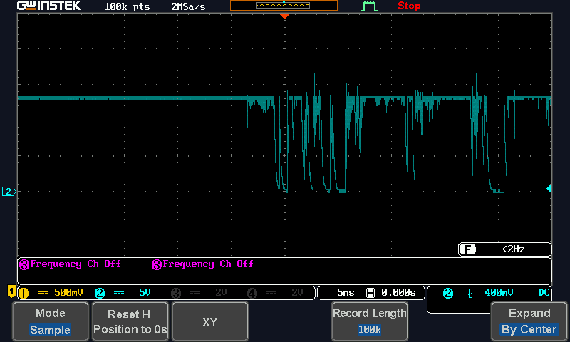
- To detect this, we first consider the expected current consumption profile in a heater circuit - it should look like a basic square wave - rising up once to heat the nozzle; then dropping down cleanly once the heating cycle is complete. MOSFETs are most commonly used for this switching, so there should be a very clean rising/falling edge without jitter present (think contact bounce on a button). The pulse width of this cycle may be 5 seconds for a heated bed or as fast as 0.5 seconds for a nozzle with small thermal mass. If at any point during the active part of the heating cycle, the current consumption exhibits anything other than being even and steady, this could indicate fatigued wires. Again - think about contact bounce. There is very brief high-frequency noise on the trace.
 The scope trace shown here is a simulation of the expected output directly from a current sense amplifier when a wire breaks contact. The current starts off holding steady, but then a lot of high-frequency noise occurs as the current bounces between zero and full.
There is already some discussion on the main page for this contest talking about the sampling speed of the MAX40080. It appears (and this makes sense in certain applications) that this particular chip may be designed more for use in totaling up overall power consumption of a device. This means that it can internally sample at a high rate, but not report all the raw data. It would just accumulate the consumption data then report it out periodically. This chip doesn't have a raw analog output from the current sensor. I think I can achieve objectives 1 and 2 via software on the RaspberryPi but will have to list objective 3 as a stretch goal and may do some testing with other current shunt amplifiers towards the end as it seems that this could all be done via hardware in a relatively simple circuit.
One other note on my project is that the Current6Click board is rated up to 5 amps max. My 3D printer consumes about 3 amps for the nozzle (at 12V) and about 10 amps for the heated bed. So for this I will be only targeting the nozzle but the exact same principles would apply for the heated bed.
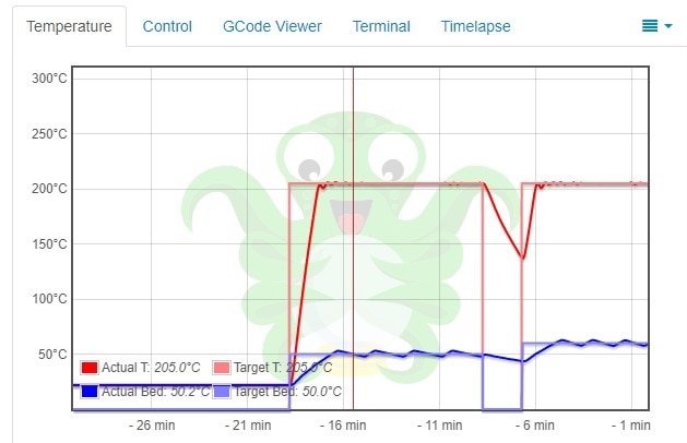
This image shows the long cycles of the bed heater, and the much faster cycles of the nozzle (which are barely visible in this graph)

Here's a video showing the kit and giving another explanation of what I'm planning on doing.
Will it work?
I sure hope so! I've had this idea rolling around in my head for a while and chose to enter this contest and use the Click board based on the lower hardware requirements. I'm still not sure I'll be able to achieve my objectives with this but will do as much as the hardware will allow. I may end up having to do some experimenting with raw hardware towards the end if I can't achieve objective #3 and time is still permitting.

-

DAB
-
Cancel
-
Vote Up
0
Vote Down
-
-
Sign in to reply
-
More
-
Cancel
Comment-

DAB
-
Cancel
-
Vote Up
0
Vote Down
-
-
Sign in to reply
-
More
-
Cancel
Children