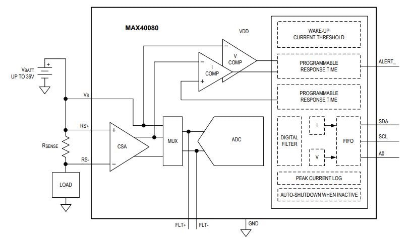
Block Diagram of Max40080
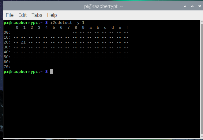
To communicate with the Max40080 and raspberry we must know the I2C address of the Max40080, The MIKROE Current 6 Click I2C Address is 0X21. after connecting the MIKROE Current 6 Click with raspberry pi it confirmed I2C Address is 0X21. In the below image you can find the address of the MIKROE Current 6 Click.
Selecting Modes of Operation
The device operates in one of the following five modes that can be programmed through the "Configuration" register:
1. Standby Mode: The device is not active, except for the I2C interface which can receive commands.
2. Low-Power Mode: The ADC is disabled, but the current sense is partially active, taking one current measurement every 50ms. The measured current is below the threshold set in the "Wake_Up_Current" register. Once the measured current reaches the threshold the device will enter into "Active Mode". No voltage measurement is taken as long as the device stays in low-power mode. For this reason, it is recommended that only current is stored into the FIFO (See the FIFO configuration register to determine what to store in the FIFO). But once the device wakes up from low-power mode to active mode, it will take either current or voltage measurement according to the Store V_I setting in the FIFO configuration register.
3. Single-Measurement Mode: The device is basically in Standby mode, but when it responds to the SM BUS "Quick Command", it wakes up and takes one current and voltage measurement, then it enters into Standby again until the next "Quick Command".
4. Active Mode: The device is active in all its functionality and measurement is continuously taken.
5. Selected Active Mode: The device automatically takes several measurements per second (according to the sample rate setting) and stays on standby in between each measurement.
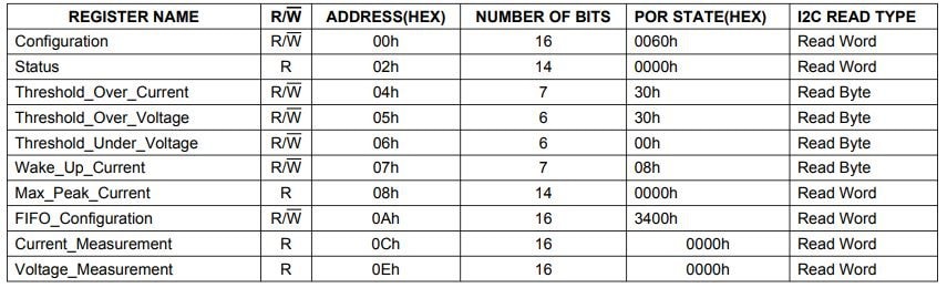
Internal Registers
The pointer register selects between the registers as shown in the below table The pointer register must be written for each I2C transaction. Register addresses are not auto-incremented during reads and write. The max peak current register resets upon reading. Write to the configuration register by writing the slave address byte, the pointer register byte to value 00h, and the data bytes. All other registers require the slave address byte, pointer register byte (04h or 05h, etc.), and 2 data bytes. If only 1 data byte is written, it is saved in bits D[15:8] of the respective register. If more than 2 data bytes are written, the additional data writes to the same register. Perform a read operation by issuing the slave address byte (write), pointer byte, repeat START, another slave address byte (read), and then reading the data byte. If more than 2 data bytes are read, the additional reads are from the same register

Operation Mode
Set bits D2, D1, and D0 to select one of the following device operation modes:
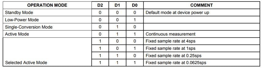
If a mode of operation is changed when a conversion is taking place, the conversion completes, and then change occurs. While on standby, the I2C interface remains active and all registers remain accessible to the master. When operating in either "Active Mode" or "Selected Active Mode" if the I2C bus is inactive for as long as 1 minute the device will automatically go into Standby Mode.
ADC Sample Rate Selection
For all the available ADC sampling rates, please note column "Data read from FIFO" is only valid for active mode. In single measurement and selected active mode, data read from FIFO can be "Both Current and Voltage" at any sample rate.
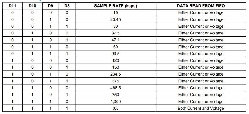
The I2C interface reads data at a maximum speed of 3.4MHz. Therefore, not all the ADC sample rates can be continuously pulled out from the device without overflowing the FIFO. The main purpose of the high ADC sample rate is for over-sampling with digital filtering. It is the responsibility of the user to ensure that the I2C can read data without overflowing the FIFO.
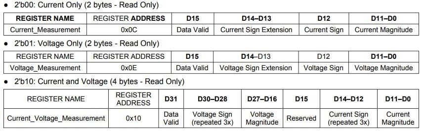
Read Current and Voltage from the FIFO
Current and Voltage data are retrieved from the FIFO through the following registers.
The FIFO Configuration Register (bits Store V_I) specifies whether the user wants to read either Current Only or Voltage Only or Current and Voltage. The read pointer is incremented after each reading.
All data are two's complements. Registers that allow reading from the FIFO: FIFO Configuration Register: bits Store IV:
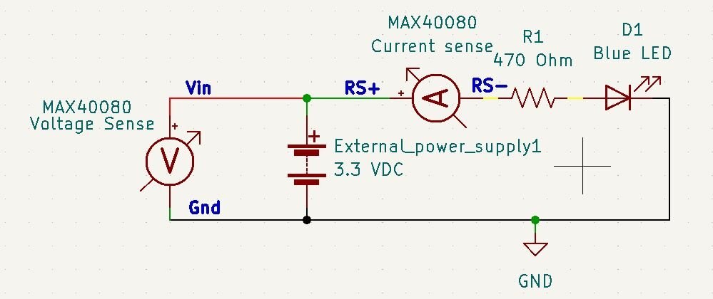
Interfacing Max40080 And Raspberry pi To Measure And Voltage.
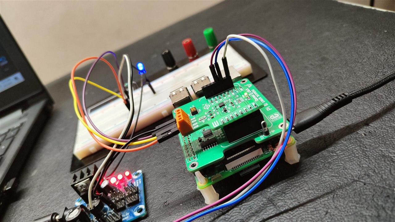
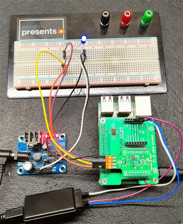
In this Experiment, I am measuring the Current Consumption of LED and Voltage Across The External Power Supply using Max40080 and Raspberry Pi 3
Circuit Diagram
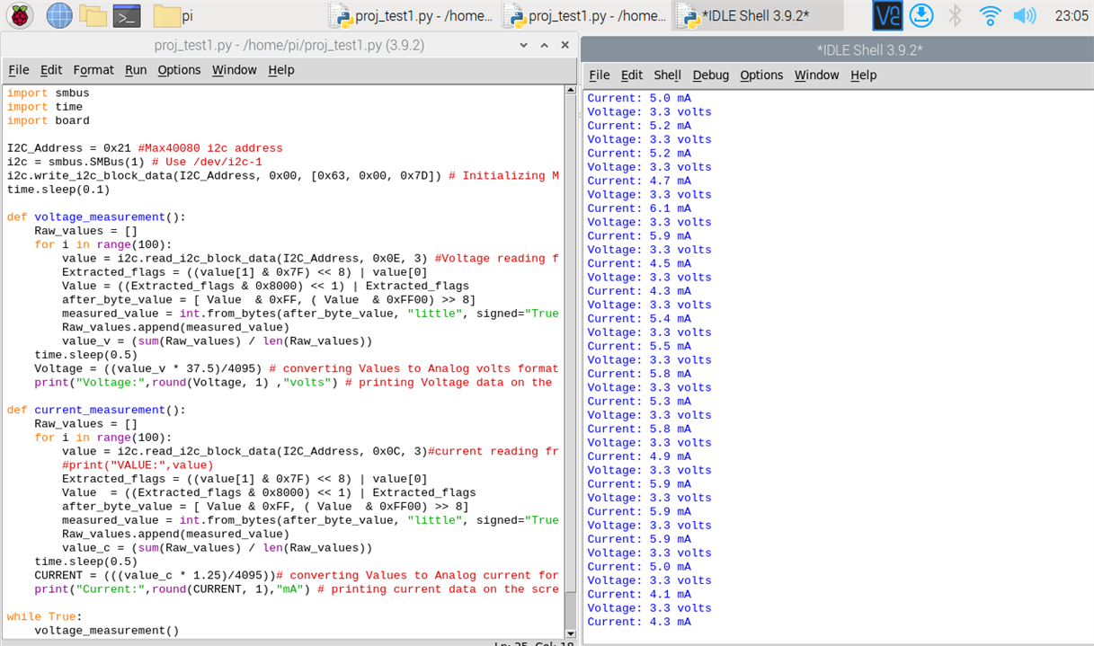
Python Code to Measure the voltage and Current Using Max40080
import smbus
import time
import board

I2C_Address = 0x21 #Max40080 i2c address
i2c = smbus.SMBus(1) # Use /dev/i2c-1
i2c.write_i2c_block_data(I2C_Address, 0x00, [0x63, 0x00, 0x7D]) # Initializing Max40080
time.sleep(0.1)

def voltage_measurement():
    Raw_values = []
    for i in range(100):
        value = i2c.read_i2c_block_data(I2C_Address, 0x0E, 3) #Voltage reading from voltage register
        Extracted_flags = ((value[1] & 0x7F) << 8) | value[0]
        Value = ((Extracted_flags & 0x8000) << 1) | Extracted_flags
        after_byte_value = [ Value  & 0xFF, ( Value  & 0xFF00) >> 8]
        measured_value = int.from_bytes(after_byte_value, "little", signed="True")
        Raw_values.append(measured_value)
        value_v = (sum(Raw_values) / len(Raw_values))
    time.sleep(0.5)
    Voltage = ((value_v * 37.5)/4095) # converting Values to Analog volts format
    print("Voltage:",round(Voltage, 1) ,"volts") # printing Voltage data on the screen

def current_measurement():
    Raw_values = []
    for i in range(100):
        value = i2c.read_i2c_block_data(I2C_Address, 0x0C, 3)#current reading from current register
        #print("VALUE:",value)
        Extracted_flags = ((value[1] & 0x7F) << 8) | value[0]
        Value  = ((Extracted_flags & 0x8000) << 1) | Extracted_flags
        after_byte_value = [ Value & 0xFF, ( Value  & 0xFF00) >> 8]
        measured_value = int.from_bytes(after_byte_value, "little", signed="True")
        Raw_values.append(measured_value)
        value_c = (sum(Raw_values) / len(Raw_values))
    time.sleep(0.5)
    CURRENT = (((value_c * 1.25)/4095))# converting Values to Analog current format
    print("Current:",round(CURRENT, 1),"mA") # printing current data on the screen

while True:
    voltage_measurement()
    current_measurement()
    time.sleep(0.1)
Output
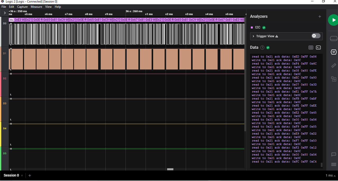
Results of Logic analyzer while Code is Executing