Introduction
This is my initial blog for the Experimenting with Extreme Environments challenge.
For Christmas last year I received a 115W bifacial solar panel. I had mentioned to my family that I wanted to build a portable DC solar module that could be used in emergencies. I then bought a charge controller and sealed AGM battery, but haven't gotten around to integrating the parts. The Extreme Enviroments Challenge presented a good opportunity to do that. I have built a number of solar powered projects with low power MCUs and sensors using 2W to 6W solar panels and USB power banks for storage, but the RPi CM4 setup will require 5W - 10W continuously - so a good project to test out the new solar panel, charge controller and battery.
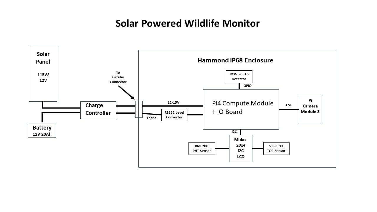
I am going to build a solar powered wildlife monitor that I can run standalone 24/7 outdoors. Here's a block diagram of my proposed setup:

The weather outdoors in the Pacific Northwest is somewhat unpredictable and can be extremely challenging for outdoor projects, especially in this era of climate change. Just this winter we had a severe ice storm that felled many old growth trees (some 40-50 feet tall) which caused extended power outages in my area and killed a neighbor about a half mile away when a tree fell through the roof of his 2nd floor bedroom where he was sleeping. And just next door, 3 of one neighbor's trees fell into another's yard, but luckily the 2 that hit the house did not break through the roof. It was just the perfect storm of several weeks of constant rain followed by the ice storm which uprooted trees because of the weight of the ice and the strong winds. Of course, this challenge is taking place during the spring so I don't think there will much ice - but we recently had freezing temperature and hail. We can have temperature differentials of 40 degrees F within a given spring day and I've had freezing temperatures damage vegetables in my garden as late as early June. So, I expect we will see a mix of sunny and rainy days with temperature ranging from 25 to 80 F. I also plan to do a hose spray test to verify the waterproof rating of the enclosure. I'm not actually what I would expect if the enclosure was exposed to ice. The polycarbonate is rated down to -30 degrees C, but I'm not sure how well it handles the mechanical stress that ice presents.
Project Features
- Solar powered with battery backup
- Pi Compute Module 4
- Pi Camera Module 3 with autofocus
- Solar charge controller with serial interface
- Microwave presence detector
- LIDAR time-of-flight sensor for proximity measurement
- Object detection using tensorflow lite model
- Pressure/Humidity/Temperature sensor
- Weatherproof IP68 enclosure
- Status monitoring using MQTT and Node-Red
Overview
In this blog I will discuss the operation of the different aspects of the project from a functional level. In the next blog I will delve into the specifications of the parts and more detailed implementation descriptions.
Power
The Pi CM4 IO can be powered by +12V via a 2.1mm barrel jack which is intended as the primary power supply input. The +12V powers 2 onboard regulators, +5V for the CM4 and peripherals and +3.3V for PCIe. The barrel jack also feeds the +12V PCIe, the external PSU connector, and the fan connector. My intent is to power the CM4 IO through the barrel jack with the output of the solar charge connector. This is the raw battery voltage and will have a range of 11-15V as the battery is being charged and discharged. I am not using PCIe or powering external peripherals, so I should be okay according to the manual which indicates that the possible range in that case is +7.5V to +28V. The onboard regulators are using AP64501 ICs which actually have a usable range of +3.8V to + 40V. Here is the excerpt from the manual:

I currently don't intend to use a fan, but if I need to - I'll need to verify the voltage tolerance.
The manual recommends allowing about 9W of power for the CM4 and peripherals, but I'm hoping that on average that I can manage it well below that by limiting the frequency of higher power activities (WiFi, inferencing) and also powering down unused interfaces since I will be running headless over WiFi (e.g. HDMI, USB). The main concern here is the amount of heat generated within a sealed enclosure. I will definitely be adding heatsinks to the CM4 components. I'm primarily concerned about when the enclosure is in direct sunlight and there is a high ambient temperature.
Status Monitoring
I currently use MQTT and Node-Red servers to monitor and datalog my IoT projects.
Here is my measurement plan for this project:
- Solar charge controller - access through serial UART
- Controller Temperature
- Battery Voltage
- Battery Current
- Solar Panel Voltage
- Solar Panel Current
- Load Voltage
- Load Current
- RPi CM4
- CPU Temperature
- CPU Frequency
- BME280 inside enclosure
- Pressure
- Temperature
- Humidity
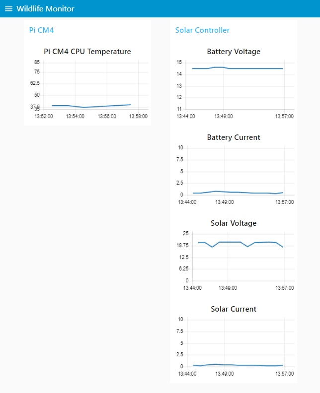
I've started to implement some of the code on an RPi4 that I'm using for development. I managed to get the UART interface with the charge controller working. Here is an example of a test dashboard that I did with the panel and controller outdoors on a partially sunny day (no load):

I have a lot of work to do to add the other parameters and clean up the charts.
I also plan to display status local to the enclosure on the 4x20 character display, but haven't decided what information I want to show.
Wildlife Monitor
The objective of the wildlife monitor is to detect and identify wildlife (animals and humans) in my backyard and to capture and serve images of the object detected. Inferencing can consume a lot of power so I only want to run it when I've detected a moving object in view of the camera. Therefore I've set up a staged detection sequence listed below:
- Object detection sequence
- Movement detected (RCWL-0516 radar)
- Object in range (VL53L1X time-of-flight sensor)
- Inference result and confidence level (TFLite model on CM4)
The microwave sensor has a broad detection range that I am going to try to limit to 6 meters and it is not very directional. It will generate an interrupt to a Python program to indicate there is movement in the general area. A TOF sensor will then determine when/if the object is within camera view/range. Then the program will publish the inference information and save the detected image.
I have some concerns about how well all this will work through the polycarbonate lid of the enclosure, so that's a risk.
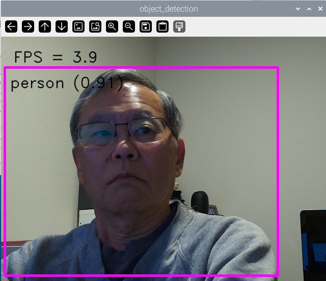
I've tried running a simple TFLite object detection model on the RPi4 without the lid and that works well although with a low frame rate. I think the real trick will be to get the camera positioned properly relative to the lid. My main concerns with the lid are autofocus performance, TOF accuracy, image quality and reflections.

Enclosure Mount
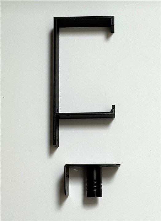
I am going to mount the enclosure on a garden pole that had been used for a bird feeder. I 3D printed a frame that allows me to attach to the pole bracket and made some minor mods to the enclosure. More details and pictures later, but here is a picture of the frame and the pole bracket.

That's it for a quick overview. More implementation details in next blog posts.
