Introduction
This is the second blog entry for my Experimenting with Extreme Environment challenge entry. In the first one the project was presented together with a brief explanation of the main chemical reaction taking place in my swimming pool. It was also described how the kit will be exposed to an extreme environment and why making this project is interesting for me.
In this new series of the blogs, an unboxing of the kit will be presented, along with a description of each component and a summary of their datasheet.
Kit unboxing
Compute Module 4
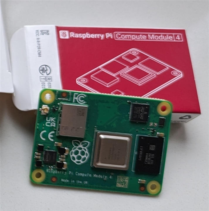
The first componet to be presented is the Compute Module 4 by Raspberry Pi, as it can be seen in Figure 1.

Figure 1. Raspberry Pi Compute Module 4
I own some Raspberry Pi boards: regular series, Zero and Pico. I have never owned a Compute Module and even if I have seen pictures before I didn't expect it to be so surprisingly small. The description from the official product page describes it as follows:
"The power of Raspberry Pi 4 in a compact form factor for deeply embedded applications. Raspberry Pi Compute Module 4 incorporates a quad-core ARM Cortex-A72 processor, dual video output, and a wide selection of other interfaces. Available in 32 variants, with a range of RAM and eMMC Flash options, and with or without wireless connectivity."
Regarding to the main specifications, they are presented in Table 1.
Table 1. Compute Module 4 specification
| Form factor | 55 x 40 mm |
| Processor |
Broadcom BCM2711 quad-core Cortex-A72 (ARM v8) 64-bit |
| Memory | 1GB, 2GB, 4GB or 8GB LPDDR4 (depending on variant) |
| Conectivity | • Optional wireless LAN, 2.4GHz and 5.0GHz IEEE 802.11b/g/n/ ac wireless, Bluetooth 5.0, BLE with onboard and external antenna options • Onboard Gigabit Ethernet PHY supporting IEEE1588 • 1 × USB 2.0 interface • PCIe Gen 2 x1 interface • 28 GPIO signals • SD card interface for SD card or external eMMC (for use only with Compute Module 4 variants without eMMC) |
| Video | • Dual HDMI interface (up to 4Kp60 supported) • 2-lane MIPI DSI display interface • 2-lane MIPI CSI camera interface • 4-lane MIPI DSI display interface • 4-lane MIPI CSI camera interface |
| Multimedia | H.265 (4Kp60 decode); H.264 (1080p60 decode, 1080p30 encode); OpenGL ES 3.0 graphics |
| Input power | 5V DC |
| Operating temperature | -20°C to +85°C |
Compute Module 4 IO Board
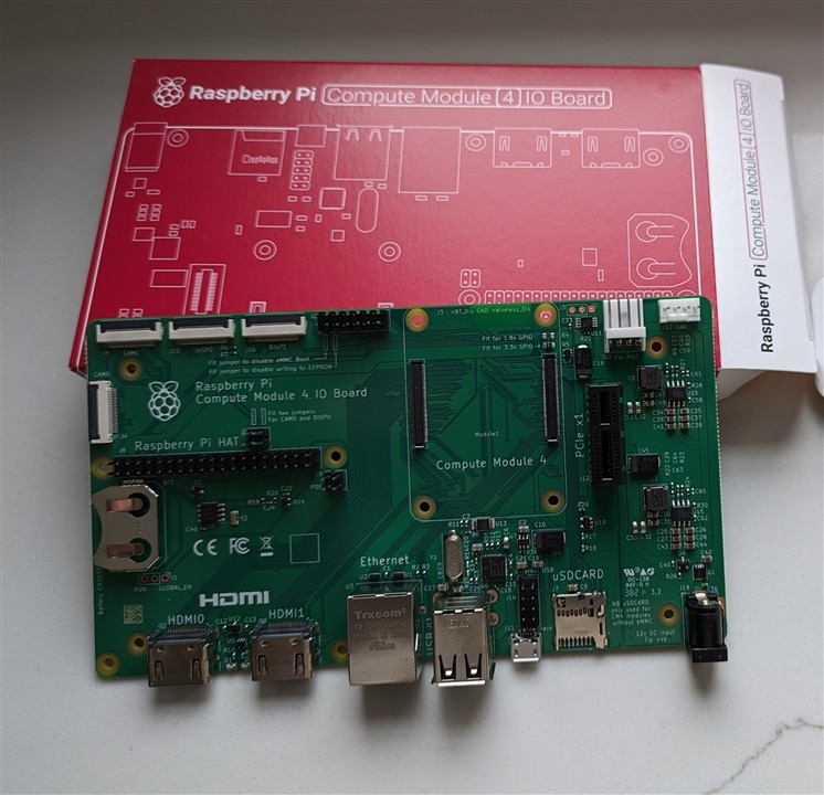
The next componet to be presented is the Compute Module 4 IO Board by Raspberry Pi, as it can be seen in Figure 2.

Figure 2. Compute Module 4 IO Board
This board is a companion for the Compute Module 4, allowing us to easily access several interfaces. Again, the official product page describes it as follows:
"Exposing every interface from Raspberry Pi Compute Module 4, the Compute Module 4 IO Board provides a development platform and reference base-board design for our most powerful Compute Module yet."
Main specification are listed below:
• CM4 socket: suitable for all variants of Compute Module 4
• Standard Raspberry Pi HAT connectors with PoE support
• Standard PCIe Gen 2 x1 socket
• Real-time clock (RTC) with battery backup
• Dual HDMI connectors
• Dual MIPI camera connectors
• Dual MIPI display connectors
• Gigabit Ethernet socket supporting PoE HAT
• On-board USB 2.0 hub with 2 USB 2.0 connectors
• SD card socket for Compute Module 4 variants without eMMC
• Support for programming eMMC variants of Compute Module 4
• PWM fan controller with tachometer feedback
MIDAS LCD Display
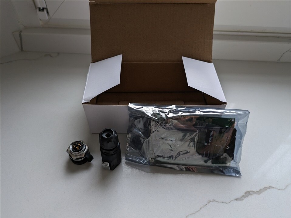
Another component included in the kit is a LCD display by MIDAS, specifically the MC42005A6W-SPTLYI-V2 model. This component is shown in Figure 3.

Figure 3. MIDAS LCD Display, connectors, antenna.
It is a LCD display that can be driven by I2C. I have not tested it yet, but as my project will be using Python, probably the best idea will be to use the library already developed by javagoza .
The main specifications are listed below:
- 20 characters x 4 lines
- STN transflective
- Yellow/green LED backlight
- Blue/black characters on a yellow/green background appearance
- I2C Interface
- 5V driving voltage
- 16 SIL top left connection
- Operating temperature range from -20°C to +70°C
- Chip on board construction
- 98mm x 60mm x 13.6mm overall size
- 77mm x 25.2mm viewing area
- 4.75mm character height
All this information can be found at Farnell product page.
Hammond IP68 enclosure
This is the key component kit of the challenge, as it will be the one in charge of enduring the extreme conditions. The model of the enclosure is the 1554VA2GYCL, it is rated as IP68 so it should be protected against dust and also be suitable for permanent submersion in water. The enclosure is presented in Figure 4.

Figure 4. Hammond IP68 enclosure
Farnell product page describes it as follows:
"The 1554VA2GYCL is a watertight clear lid polycarbonate Enclosure ideally suited for mounting printed circuit boards or DIN rail mounted components. The clear polycarbonate lid allows for maximum visibility of protected internal components. It has gasketed lid with two piece tongue and groove construction provides protection against access of oil, dust and water. The lid is secured with self-captivating - M4 stainless steel machine screws, threaded into integral stainless steel bushings for repetitive assembly and disassembly. Stainless steel hardware is used to avoid corrosion caused by dissimilar metals."
Miscellany
The other components included in the kit are two circular connectors, which allow us to power our prototype while still being able to ensure protection. I must point out that the connectors are not IP68 but IP67, which means that they will only stand immersion up to a depth of 1 m for up to 30 minutes. These connectors are made by AMPHENOL COMMUNICATIONS SOLUTIONS.
The RF Antenna model 146153-0050 by Molex is suitable for different communication protocols like Wi-Fi, BLE, Thread, Wireless Hart or Zigbee.
All these components are presented in the previously depicted Figure 3.
Extra
Another component I already owned must be presented, even if it is not part of the kit, as it will be a very important part of this challenge.
It is a Dallas DS18B20 sensor sealed into a metal tube. For communication, it uses a 1-Wire serial interface.
It can measure temperatures ranging from -55 ºC to 125 ºC, with an accuracy of 0.5 ºC being enough for our project.
The next blogs will feature the prototype building process and the first coding steps.
Note: I am struggling to get free time to be able to do this, so the pictures included are the ones I took when I got the kit. If I have time, I will update them.
