


Software Development
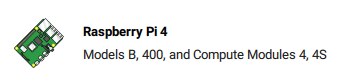
Starting new projects with new hardware and new software is always an interesting journey and this challenge has not been the exception. In this context, new means new to me though not necessarily to the world in general. I've used Raspberry Pi hardware and software since all the way back to 2013 when I was using the RPi 1 with 32-bit Debian 7 (Wheezy) and of late have been using RPi 4s with 64-bit Debian 11 (Bullseye). I have never used a Compute Module before so the CM4 is new hardware for me. It's roughly a variant of the RPi 4 and very similar in capability when paired with the CM4 IO board, so I'm going to start doing development of the camera and sensor software on an RPi 4 and try to migrate that directly to the CM4 (use the same SD card). It will be interesting to see how much tweaking is required.
Raspberry Pi Operating System
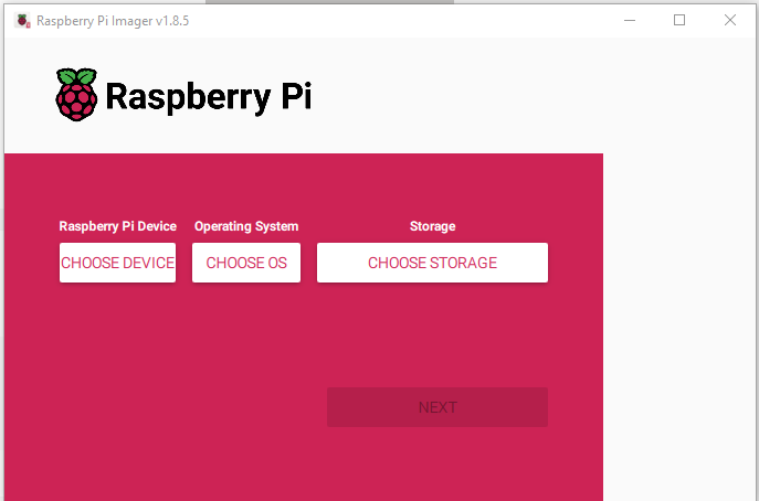
Late last year the Raspberry Pi OS transitioned to Debian 12 (Bookworm) so I thought that I would give that a try. I went the route of using the Raspberry Pi Imager to flash the image onto the uSD card (the uSD interface doesn't work on CM4's with eMMC but no issue here since we are using Lite modules without eMMC).
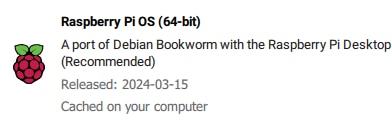
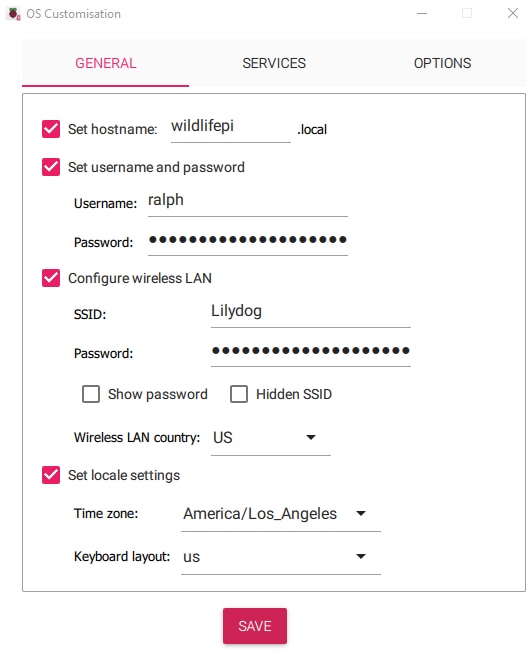
I chose to go with a RPi 4 64-bit Desktop on a 32GB uSD card
![]()
I then added some standard customisations to allow for headless operation.
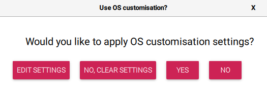
Adding a Hostname, WiFi config, and Locale info
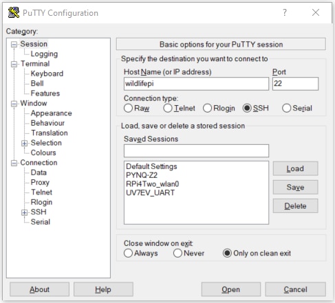
And off we go...
Next to log in via SSH using putty with the wildlifepi hostname
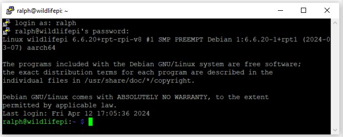
Then sudo raspi-config to enable additional Interface options
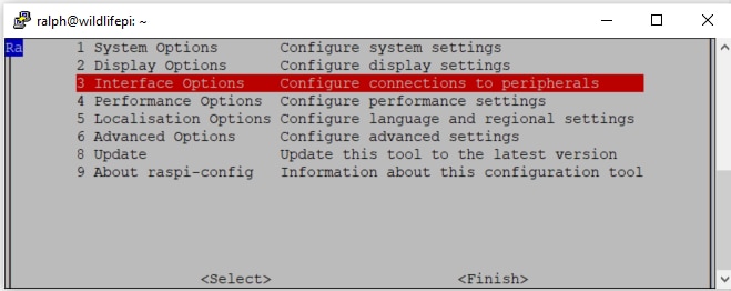
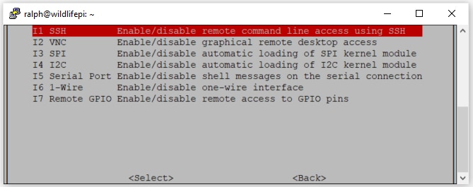
In addition to SSH which is already enabled, I enabled VNC for graphical interface and I2C for the sensors and display. I made sure that the Serial Port login shell was disabled since that would interfere with the UART operation.
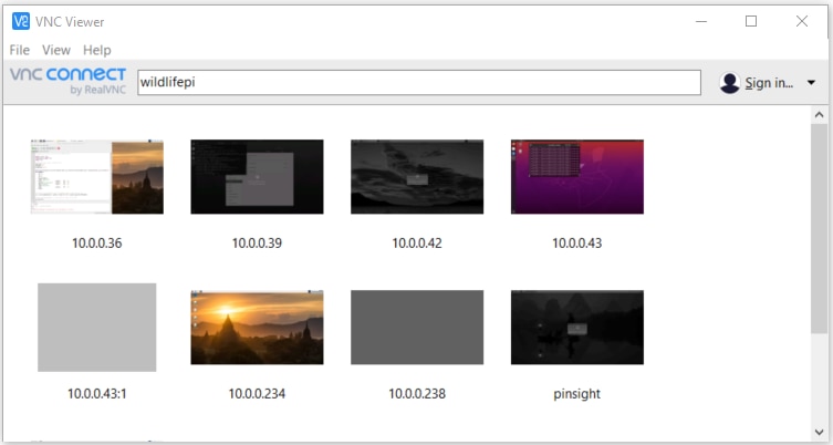
Then start a VNC session (I use RealVNC)
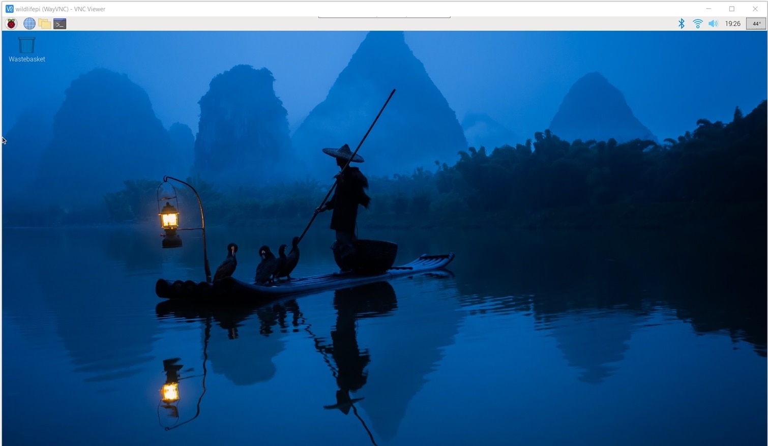
Now to install development software that I'll need for the project.
Project Virtual Environment
When I started to install the software I encountered a surprise. Apparently, as of Bookworm, the OS is now enforcing a split in package installation between site-wide packages which are installed with APT and Python packages which are installed with PIP. I started to run into errors about externally-managed-environment. I found the following on the Raspberry Pi documentation site:
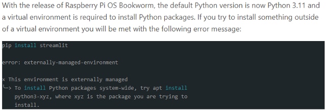
There are ways to work around using virtual environments, but I decided to accept the paradigm shift as there are some advantages in portability with virtual environments.
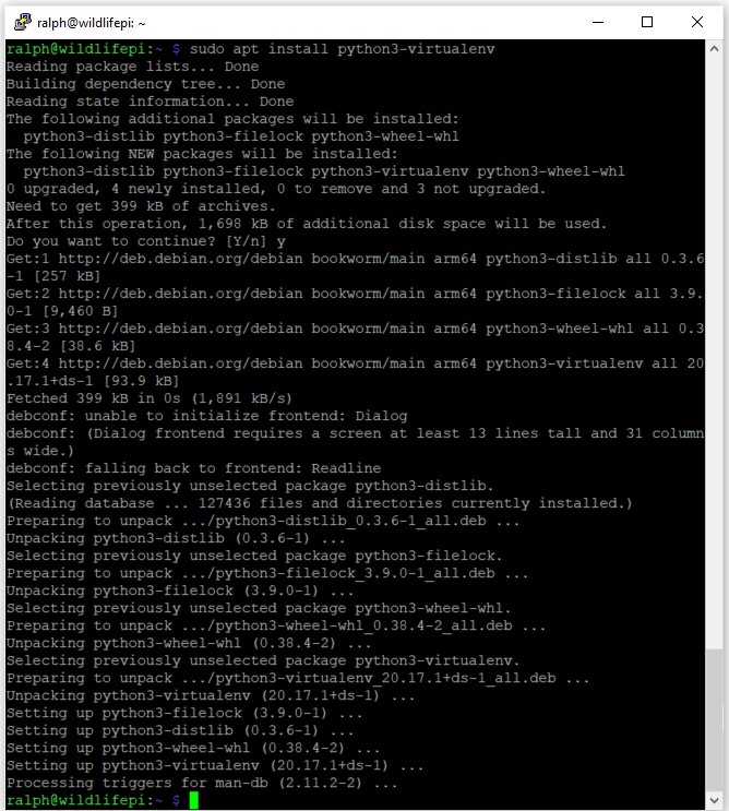
Installing the virtual environment software is straightforward:
sudo apt install python3-virtualenv
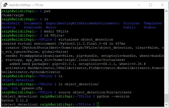
Once virtualenv is installed it can be used to create any number of virtual environments simply by using a single argument that is the directory where the environment files and configuration will be stored. In my case I will be focused on object detection so I created a directory under TFLite called object_detection.
virtualenv object_detection
This created a bin and lib directory and a pyvenv.cfg file that contain the scripts and configuration and libraries associated with the Python virtual environment.
Then the venv needs to be activated by sourcing the activate script.
source object_detection/bin/activate
With the venv active, PIP can be used normally and all installed packages are local to this venv.
An initial check of installed packages using pip3 list shows that only the basic package tools have been installed.
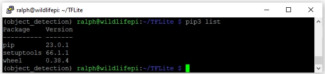
Now my virtual environment is ready for software development.
Pi Camera Software
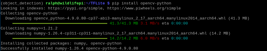
Besides picamera2 (libcamera based python library) which is included with OS, I'll need to install two packages to facilitate object detection:
- OpenCV - real-time optimized Computer Vision library, tools, and hardware
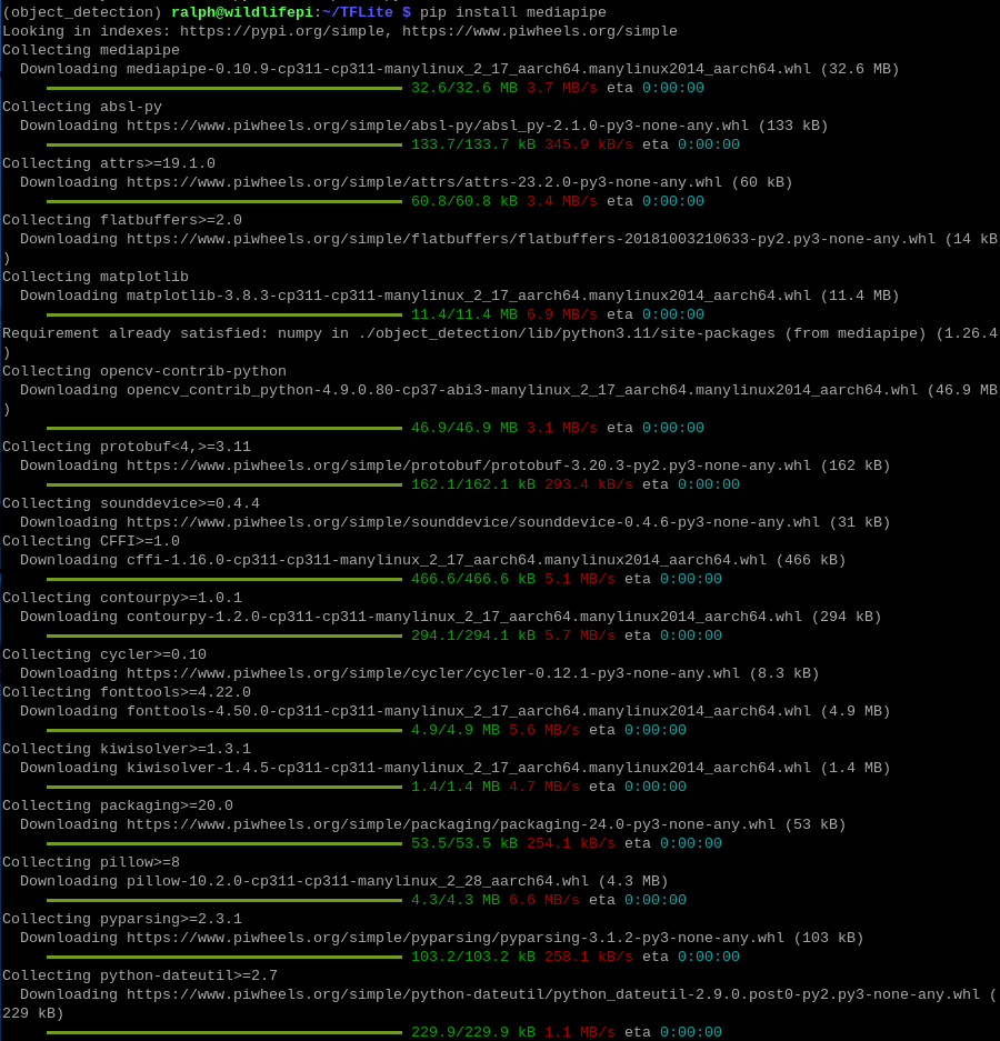
- MediaPipe - cross-platform, customizable ML solutions for live and streaming media
Use PIP to install the packages and list all of the libraries installed:
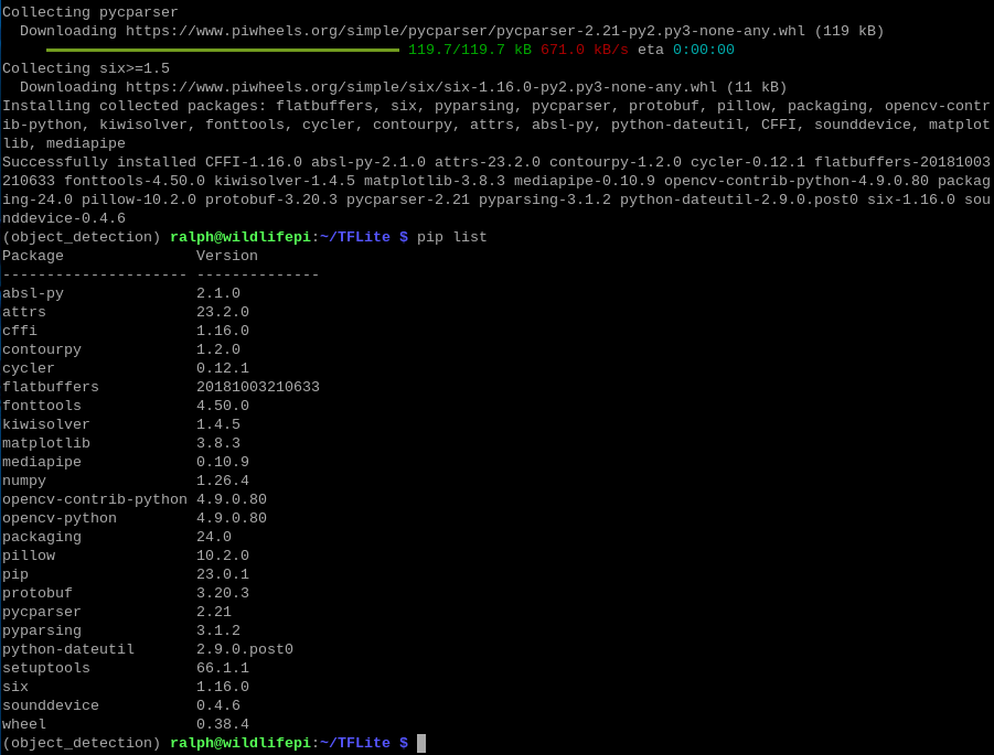
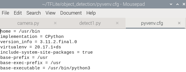
It was interesting that picamera2 does not show up in the list. And when I tried to run basic camera programs it was indeed not available. It turns out that when I created the virtual environment I should have used the --system-site-packages to inherit any OS included packages.
I found that I could edit the pyvenv.cfg file to set that option to true and it would take effect at the next activation.
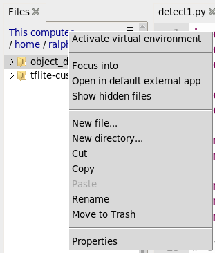
I also discovered that you can manage the virtual environment within the Thonny editor which is very convenient. To activate just use View->Files and right click the virtual environment directory.
Quick test of the camera
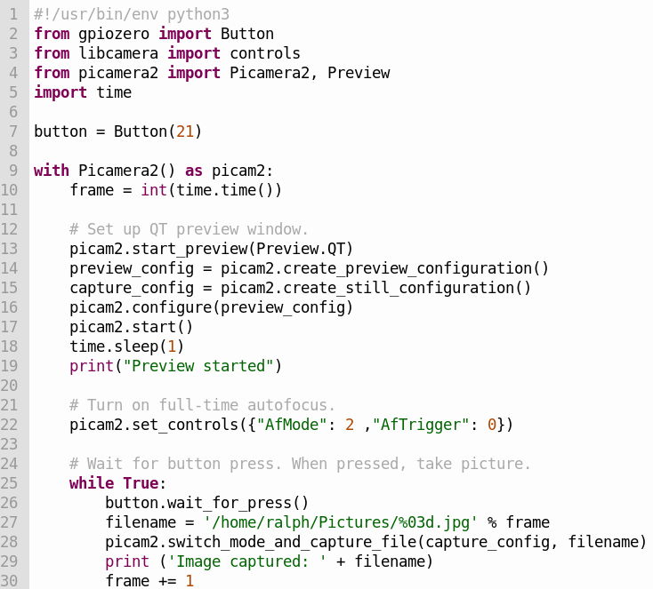
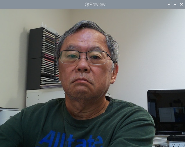
The preview window
Display Software
I still haven't decided what information that I'm going to put on the display. I'll have to admit that I found the documentation for the Midas display somewhat lacking (a schematic would have been helpful and also the I2C address). It uses a RW1063 controller that I'm not familiar with but from what I've read should be compatible with I2C libraries that interface to the HD44780 controller and the address can be found using an I2C address scanning program. I have a more generic 20x4 display that uses an I2C backpack and I'm going to use that initially and try swapping in the Midas display later (I need to get a small potentiometer to adjust the contrast for the Midas display and also wire the header pins). If I have issues when I use the Midas display I will try using the library that javagoza developed.
There are quite a few Python libraries for 20x4 character displays. Most are pretty barebones so I just chose the rpi-lcd which can be installed with PIP. And ran a simple "Hello World" as a test.
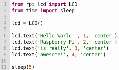
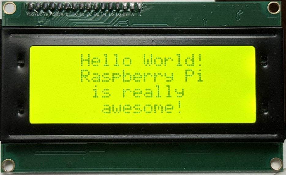
There are a couple of quirks with this library
- The module import name is rpi_lcd instead of rpi-lcd
- You can't specify the I2C address in the program - it needs to be changed in the library _init_.py file
Sensor Software
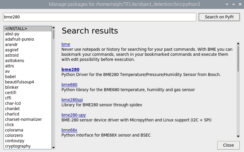
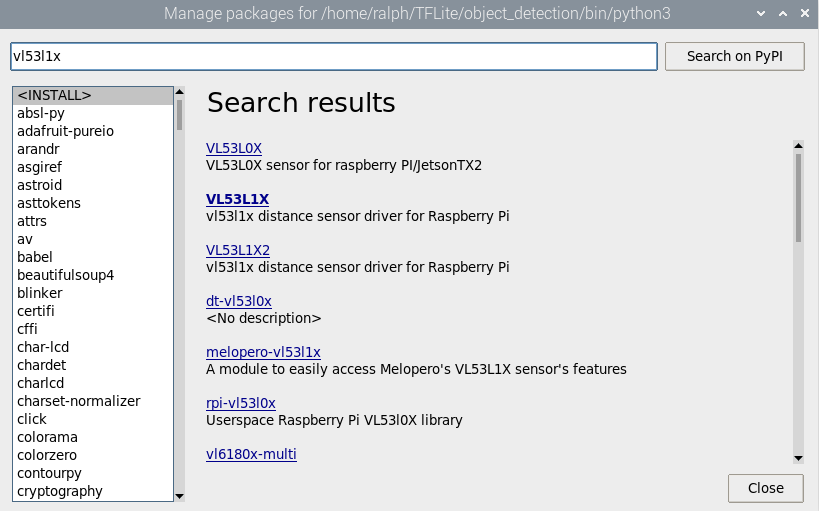
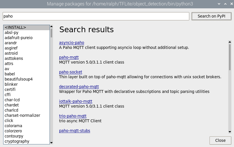
I have 2 I2C sensors that I am using, the BME280 PHT sensor and the VL53L1X LIDAR sensor. Both sensors have Python libraries that can be installed with PIP. Or an even easier way that I found is to use the "Tools->Manage Packages" interface in Thonny and you can search for and install packages using PyPi. Just in all cases need to remember to activate the virtual environment first.
Simple test programs again...
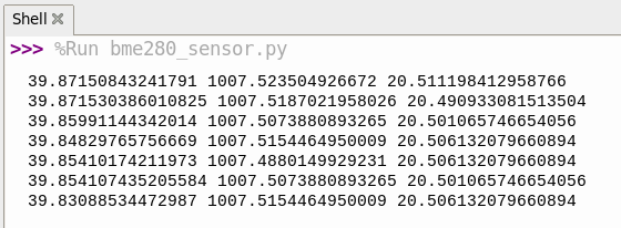
BME280
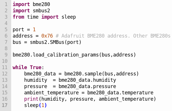
The shell output
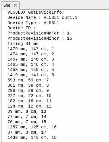
VL53L1X
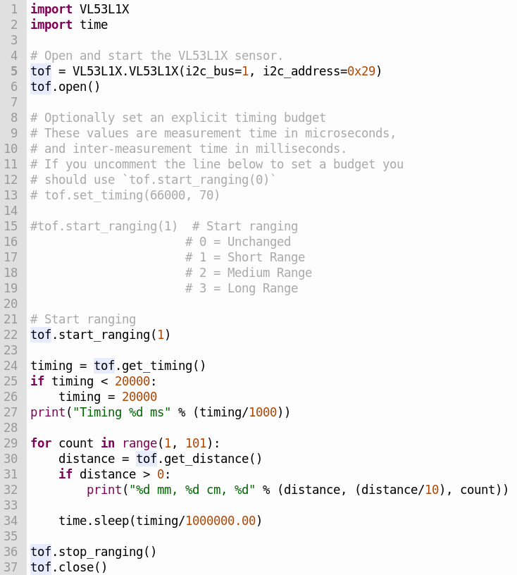
Shell output
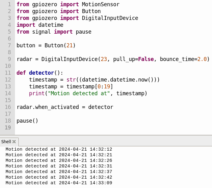
RCWL-0516 Software
The RCWL-0516 is a microwave doppler radar sensor that provides a Trigger pin to indicate that movement has been detected. I am going to use GPIO23 as an interrupt to the CM4 to cause it to run a function to determine whether or not to turn on the camera and start the object detection routine. For the initial test I am just going to use the DigitalInputDevice from the gpiozero library to test the detection of Trigger signals caused when I am moving in range of the sensor. I tried the MotionSensor from the gpiozero library but had intermittent results.
Charge Controller Software
I've never used the UART on an RPi4 so I thought that I would try running some Arduino code that I found as a quick test. The Renogy charge controller uses a ModBus interface over RS-232 and I found an example using the https://github.com/syvic/ModbusMaster repository to read the charge controller registers. Unfortunately that code is 12 years old and after a nightmare of a time trying to get it to compile, I gave up.
I then found the https://github.com/sophienyaa/NodeRenogy repository that uses NodeJS code to read the charge controller registers and publish the data using MQTT. That seemed exactly what I needed so I did a quick test of the RS-232 to TTL level converter connections using the UART interface on a Xiao SAMD21 and then moved on to trying the NodeJS code on the RPi4.
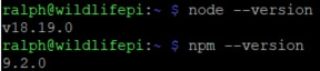
Next, I needed to install the Node.js and npm packages using APT:
sudo apt update
sudo apt install nodejs npm
After lots of output ...
Now that nodejs and npm are installed, I need to clone the repository
git clone https://github.com/sophienyaa/NodeRenogy.git
To finish the installation I needed to cd into the cloned NodeRenogy directory and install the dependencies using the following commands:
npm install
sudo npm link
Here is the package.json file that lists the dependencies
{
  "name": "noderenogy",
  "version": "1.0.0",
  "description": "Utility to retrieve data from Renogy solar controllers and publish it to MQTT, written in NodeJS",
  "main": "index.js",
  "scripts": {
    "test": "echo \"Error: no test specified\" && exit 1"
  },
  "author": "mickwheelz",
  "license": "MIT",
  "bin": {
    "node-renogy": "./index.js"
  },
  "dependencies": {
    "async-mqtt": "^2.6.1",
    "modbus-serial": "^8.0.4",
    "mqtt": "^4.2.8",
    "pino": "^6.13.3",
    "pino-pretty": "^7.0.1",
    "yargs": "^17.2.1"
  }
}
Note: By default on the RPi4 the UART assigned to GPIO14 (Tx) and GPIO15 (Rx) is mini UART (/dev/ttyS0). The downside of the mini UART is that it is dependent on the core VPU clock so it may be unstable if the clock frequency changes. The PL011 UART (/dev/ttyAMA0) available on these pins is used for wireless which I am also using. I am going to try using the mini UART and see if it causes me any problems. There are other UARTs available on other pins on the RPi4 and I will try those if I have issues with the mini UART.
Once node-renogy has been installed, using it is as simple as invoking it with the UART device name and MQTT server ipaddr as arguments:
node-renogy -s /dev/ttyS0 -m 10.0.0.234
Here is a JSON packet that was received over MQTT:
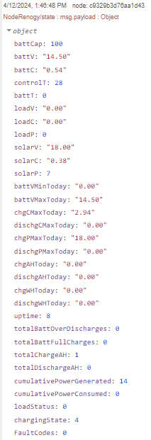
MQTT
I have a dedicated MQTT server running on an RPi4 on my local network. That same server also serves Node-Red, Node-Red Dashboard, InfluxDB and Grafana - an IoT hub of sorts.
In order to use MQTT we need to install an MQTT client. Again I'll use Thonny Manage packages to install paho-mqtt.
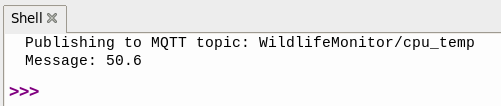
Test program to get the RPi4 cpu temperature, display it and publish it to the topic "WildLifeMonitor/cpu_temp" on my MQTT server at ipaddr 10.0.0.234
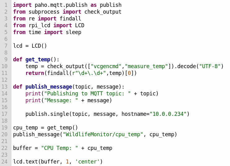
The shell output of the program
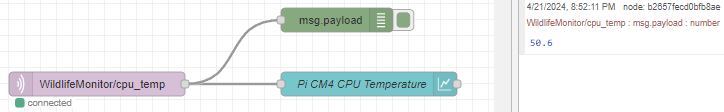
And the debug output of the Node-Red Flow on the server
Node-Red
I use Node-Red to create Dashboards to visualize device data.
This is a simple Wildlife Monitor Flow to plot Pi CM4 temperature and Charge Controller voltages and currents in Dashboard Charts
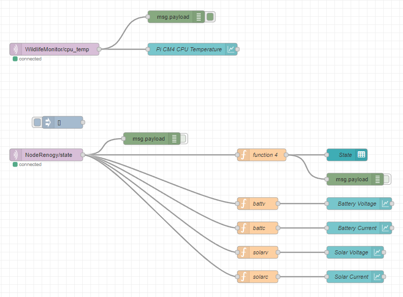
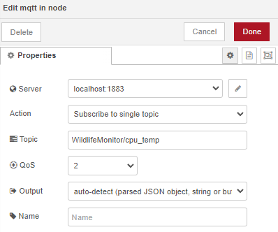
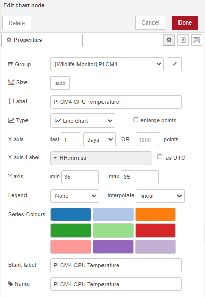
The MQTT Input node subscribes to a topic (e.g. cpu_temp) on the MQTT server and passes that data to the Chart node
Then the Chart node plots the data in the Pi CM4 group on the Wildlife Monitor dashboard
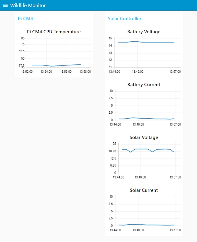
And the resulting Dashboard
More work ahead
Now I've been able to test software to access all of the hardware components. There is still a lot of work ahead to create a fully functional application and move it from the RPi4 to the CM4. I need to find an appropriate tensorflow lite (TFLite) model to use for detecting wildlife (animals, people). And, of course, I need to integrate all of the hardware pieces and verify that the camera and sensors work properly through the transparent lid.

